Research Note
Numerical Study on Reinforcing
of Thin Walled Cracked Metal
Cylindrical Columns Using FRP Patch
M.Z. Kabir
1;and A.R. Nazari
1Abstract. In this paper a new technique was proposed for the repair of defected metal columns. The nite element method was chosen to nd out the adequacy of the proposed method, regarding, the load carrying capacity of two types of thin walled cylindrical columns with L=D = 10 and 20 along with circumferential and longitudinal cracks. The study considers the non linearity behavior in both material as well as geometrical characteristics. Various congurations of the composite patches made from carbon-epoxy were assumed on the cracked region and the inuence of a patch on the load carrying capacity of the columns was examined. The obtained results indicate that composite material can not only compensate the eect of damage on column buckling load, but also increase buckling strength to a level even greater than in an intact one.
Keywords: Repair; Cracked metal column; Buckling load; FRP patch; Compression loading.
INTRODUCTION
Nowadays, composite materials are utilized in various elds of industry and building construction due to their valuable properties such as the high value of strength to weight ratio and easy installation. From the prominent usage of these materials in civil engineering, it was addressed to the reinforcement and repair of concrete members [1]. Generally this application has been utilized more for concrete rather than metallic structures, while metallic structural members can be exposed to various damages and defects in their ser-vice lives, one of which being crack may stem from dierent factors such as sudden damage, corrosion environment or fatigue loading. Thus, demand for an ecient repair against these phenomena is a major concern of design engineers. On the other hand, using metallic patches and stieners requires heavy equipment. Even then welding of these structures, considering their small thicknesses, can be followed 1. Department of Civil and Environmental Engineering, Amirk-abir University of Technology, Tehran, P.O. Box 158754413, Iran.
*. Corresponding author. E-mail: [email protected]
Received 1 February 2010; received in revised form 15 June 2010; accepted 21 August 2010
by temperature defects, extra residual stresses and unexpected deformation.
The presented technique was previously explored for repairing defected metallic structures, especially under tension loading rather than compression. As a literature review, Baker and Jones [2,3] studied a repair technique using adhesively bonded boron/epoxy composite patches, which is widely considered as a re-liable method for repairing cracked plates under tensile loading. The authors of the present paper investigated the inuence of patched FRP pultruded sheets on metal plates in the buckling phenomenon [4]. Teng and Hu [5] covered steel tubes and cylindrical shells under compression loading by FRP jackets during experi-mental and nite element studies and they displayed this technique as a useful method for ductility increase and collapse hindering of these structures. Silvestre et al. [6] investigated the non-linear behavior and load carrying capacity of the CFRP-strengthed open-section columns from cold-formed steel using pultruded composite sheets, and they observed a considerable increase in the buckling load and improvement of the post buckling behavior for these members. Shaat and Fam [7-9], using FRP sheets on hollow square columns, investigated the inuence of these patches on the load-bearing capacity of the columns. They developed an
analytical model for their experimental specimens and veried the analytical manipulation by experimental results. They also extended their theory for various characteristics of the columns, such as slenderness and initial out-of-straightness.
The main contribution of the current study is the stability of a repaired metal cylinder using an FRP patch. The inuence of the crack in both longitudinal and circumferential directions was considered on the load carrying capacity of the cylinder. The methodol-ogy is based on numerical study. All the assumptions here are based on experimental observations by authors presented in other studies. The columns were made of steel alloy in those tests and here they are assumed from an aluminum alloy [10]. The obtained results would establish the presented retrotting technique as a unique method for repairing and reinforcing thin walled tubular sections.
PROPOSED MODELS
To follow up the subject of the paper, the selected models are of two various diameters and of identical length and thickness as L = 1000 mm and t = 1 mm. The diameters were determined as D = 50 mm and D = 100 mm denoting the cylinder aspect ratio for exploring two distinct buckling mode shapes. The considered cracks on the columns were chosen in longi-tudinal and circumferential directions to investigate the inuence of crack in two major orientations. The length of the longitudinal crack was assumed 0.2 of the column length (C=L = 0:2) and similarly the circumferential crack length was 0.2 of the column section perimeter (C=2r = 0:2).
The column was made of an aluminum alloy (T-6061) with elastic modulus, yield stress and Poisson ratio equal to 71.7e3 MPa, 240 MPa and 0.33, respec-tively. It should be emphasized that due to the almost attening out of stress strain in the plastic domain for the selected aluminum, T-6061, the material behaves in an elastic-fully plastic manner. By placing two rigid plates at both ends, the end conditions of the columns were considered as clamped. The criterion of the cylinder shortening provided movement between the two rigid plates. The reinforced material was chosen as carbon ber and epoxy resin with mechanical properties as listed in Table 1. In this table, E1 is
the module of the composite in the bers direction,
E2 is the composite module in the matrix direction,
12 is the major Poisson ratio in the 1-2 plane, G12
is the major shear module in the 1-2 plane, XT
denotes the tensile strength in the bers direction, XC indicates the compressive strength in the bers
direction, YT denotes the tensile strength in the matrix
direction, YC represents the compressive strength in
the matrix direction and, nally, SL and ST denote
the shear strength in the bers and matrix directions, respectively.
Figure 1 shows the schematic view of the re-paired cylinder. Here, the important problem is the interaction between the cylinder and the FRP patch. To determine this relation regarding that observed in the experimental study about contact between the FRP patch and cylinder in [10], in the present study, any debonding between the patch and cylinder was ignored and the movement of the patch elements de-pended on the movement of adjacent cylinder elements. The assumption was validated in the experimental observations carried out by the authors in previous work [5]. Of course, the mentioned hypothesis ignores any debonding between a composite patch and a metal cylinder.
FE MODELING Cracked Cylinder
The common commercial program, ABAQUS [11], was utilized for the FE modeling and analysis of the assumed columns. For modeling of the columns, nonlinear behavior in both material and geometry
Figure 1. Schematic view of the repaired cylinder by composite patch.
Table 1. Mechanical properties of the used FRP. Material E1
(MPa) E2 (MPa)
12 (MPa)
G12 (MPa)
XT (MPa)
XC (MPa)
YT (MPa)
YC (MPa)
SL (MPa)
ST (MPa)
t (mm per
layer)
domains was considered for the models. Loading on the structures was carried out considering a low velocity (V = 5 mm/s) on the top rigid plate. In order to consider the nonlinearity in geometry, at the beginning, the buckling analysis was performed and then by imposing the combination of obtained mode shapes, considering them as an initial imperfection, the non linear analysis was conducted. The amplitude of the small deformations was considered about 1 m. The assumed boundary conditions, both for the top and bottom plates, were implemented as three rotational and two translational movements. The contact between the rigid plates and the cylinder edges was dened both in normal and tangential directions. The normal contact was designated as \hard contact" and the tangential contact was introduced with a friction ratio to prevent sliding between the plate and cylinder. The presented results are the axial load-end shortening curves, which were compared for the intact, cracked and repaired columns. Both cylinders and rigid plates were modeled using \shell" elements, and for this purpose, \S4R" element with 4 nodes and 6 degrees of freedom (three translational and three rotational) per node was chosen from the element library of the \ABAQUS.CAE". A mesh convergence study for an intact cylinder with L=D = 10 was carried out to choose the appropriate size for mesh dimensions (see Table 2). The buckling process is explained as follows: The plastic buckling takes place at two ends and the diameter of the cylinder increases in this region. Considering the yield stress, y, equal to 240 MPa, the
yield load, Py, is then estimated as = 75.4 KN, which
is similar to numerical FEM results. Thus, starting with a 3030 mm2nite element mesh, using non-linear
analysis, a convergence study was conducted for an intact cylinder with L=D = 10. The result from each renement of the mesh is compared with that of the classical buckling equation (Py) and is summarized in
Table 2. Accepting an error margin of 1% for the non-linear buckling load, a mesh consisting of 4000 elements and 10 mm10 mm element size was adopted in the
Table 2. Mesh convergence study of the cylinder with L=D = 10.
Mesh Size (mm)
Number of Elements
Buckling Load (KN)
Error (%)
30*30 428 77.578 2.90%
20*20 1000 77.059 2.20%
15*15 1745 76.682 1.70%
10*10 4000 76.169 1.02%
7.5*7.5 6951 76.116 0.95%
5*5 15600 76 0.80%
numerical analyses. Regarding the dependence of the accuracy of the results on the ratio between mesh size and cylinder radius, the size of mesh for a cylinder with L=D = 20 was chosen as half of a cylinder with L=D = 10. This size of mesh was extended for the entire structure except at the vicinity of the crack tips. Observation of the stresses around the crack tip shows that the mesh size in this region has a dominant eect on the stress contour in the region. It was decided to fragment the mesh size at this region to about 1/16 the size of mesh in other regions through four steps [12]. Triangular elements were chosen for meshing of the regions near the crack tips in order to prevent making narrow rectangular elements in these areas.
Composite Patch
For modeling of FRP patch connement, various meth-ods have been implemented by researchers. In the current study, the composite patch was modeled using shell elements. The centroid of the patch elements was located at an appropriate distance from the centroid of the metal cylinder. An oset was assigned to all con-tributed nodes for contact between cylinder and patch nodes. The continuity between the patch and cylinder during the loading process was fully established and the deformation of these two parts was assumed identical. Using \tie" constraint as the direct contact between patch and cylinder nodes, the full bonding will, then, be provided. By dening this constraint, the degrees of freedom of the patch elements were introduced as slave elements and those of the cylinders as master elements with consideration of no debonding between the patch and cylinder. \S4R" shell elements were adopted to model the laminated composite patch with orthotropic characteristics and a progressive damage capability. For all proposed models, the bers were oriented in a circumferential direction in the retrotting of both crack types: longitudinally and circumferentially.
Progressive Damage
The elastic damage modeling was investigated in the same way as damage initiation and progression in brittle anisotropic materials such as FRP. In this theory, the damage is modeled by reducing the stiness of materials, based on Hashin and Rotem criteria (1973) [15,16]. In the present modeling, four various modes are considered for damage of the composite: - Fiber rupture in tension.
- Fiber buckling and kinking in compression.
- Matrix cracking under transverse tension and shear-ing.
- Matrix crushing under transverse compression and shearing.
On the basis of the four mentioned modes, four damage criteria are introduced to initiate the damage as follows:
- Ft f = ^11 XT 2 + ^12 SL 2 :
- FC f = ^11 XC 2 :
- Ft m= ^22 YT 2 + ^12 SL 2 :
- FC m = ^22 2ST 2 +
"YC 2ST
2
1 #
^22
YC +
^12
SL
2 :
In the above equations, ^11, ^22, ^12 are components
of the eective stress tensors which are intended to represent the stresses acting over the damaged area. is a coecient that determines the contribution of the shear stress to the ber tensile initiation criterion and which varies between 0 and 1, its high value being assumed here. At the end of each state of analysis, these criteria were checked on each element of the FRP, whether the damage was initiated or not. Having damage evolution denition for each mode, the stiness of the damaged element is replaced by zero in that mode. For a metal cylinder, the Von-Mises stress criterion was used and for FRP elements, the Hashin damage criterion was evaluated. These are shown with: HSNFTCRT for maximum value of the ber tensile initiation criterion experienced during the analysis or ultimate FT
f; HSNFCCRT for maximum value of
the ber compressive initiation criterion experienced during the analysis or ultimate FC
f ; HSNMTCRT for
maximum value of the matrix tensile initiation crite-rion experienced during the analysis or ultimate FT
m,
and HSNMCCRT for maximum value of the matrix compressive initiation criterion experienced during the analysis or ultimate FC
m.
DISCUSSION OF THE RESULTS
Repair of Circumferentially Cracked Column with L=D = 10
A relatively long cylinder was included in this study in order to investigate the eciency of the proposed tech-nique to repair cylinders which have plastic buckling. The load versus axial shortening in a non-linear manner is depicted in Figure 2, in a non-dimensional graph where the vertical axis is the ratio of the applied load (P ) to the ultimate strength (P0) of the intact cylinder
and the horizontal axis gives the ratio of the end shortening () over the cylinder length (L). According to the gure, in the presence of a circumferential crack with C=2r = 0:2, the ultimate strength and
Figure 2. The inuence of repair with composite patch on the non-dimensional load-deection graph of the circumferentially cracked column with L=D = 10 and C=2r = 0:2.
absorbed energy of the cylinder were decreased by 37% and 27%, respectively; \C" denotes the length of the crack. Figure 3 shows the buckling deformations of the cylinders in states of being intact and cracked. It is seen that the buckling of the column deforms from the elephant foot mode of an intact cylinder to the local crippling mode at the cracked region for a cracked cylinder. In the rst attempt, only a one-ply composite patch made of carbon-epoxy with ber orientation in the circumferential direction and with a length of \200 mm" was used on the cylinder axisymmetrically relative to the crack. The maximum buckling load was considerably promoted, as can be seen in Figure 2. The next attempt was specied by strengthening of the cracked region using a two-ply composite patch. Figure 2 also shows its inuence on the load bearing behavior of the repaired column. Figure 3d shows the buckling deformation of this cylinder, which was occurred out of the patch zone. Figure 4 shows the Hashin damage criterion about the tensile bers for both types of composite patch.
Repair of Longitudinally Cracked Column with L=D = 10
In order to investigate the inuence of the longitudinal crack on this column, the size of crack was assumed about 0.2 of the column length at the center. Figure 5 shows the non dimensional load deection curves of longitudinally cracked cylinders. The repairing patch has enhanced the cracked cylinder buckling load up to the intact one. The buckling form of the cylinder is observed in Figure 6 in the presence of a longitudinal crack. The cylinder inclines outward from the cracked region followed by its collapse. To repair this cylinder, a two-ply patch with a length of \300 mm" was
Figure 3. Buckling deformations of the column with L=D = 10 in states of (a) intact; (b) un-repaired circumferentially cracked; (c) patched by 1-ply patch; and (d) patched by 2-ply patch.
Figure 4. Hashin damage criterion about the tensile bers in (a) 1-ply patch and (b) 2-ply patch.
Figure 5. The inuence of repair with composite patch on the non-dimensional load-deection graph of the longitudinally cracked column with L=D = 10 and C=L = 0:2.
attached on the crack axisymmetrically relative to the crack centre. In Figure 6b, the buckling form of the retrotted column appeared in an elephant foot mode at one end of the cylinder. Based on the obtained results, none of the damage criteria was
Figure 6. Buckling deformations of the longitudinally cracked cylinder with L=D = 10 in states of (a) un-repaired longitudinally cracked and (b) repaired by composite patch.
referred to FRP failure, which indicates the successful performance of an externally bonded composite patch on longitudinally cracked circular columns.
Repair of Circumferentially Cracked Cylinder with L=D = 20
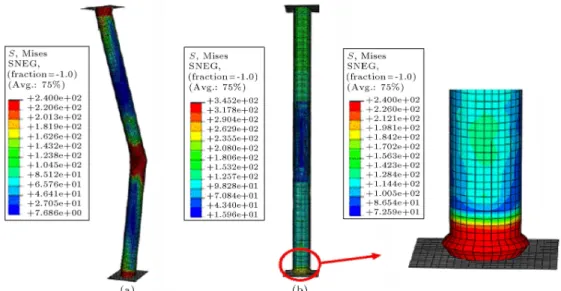
This section was studied in order to investigate the ap-plicability of the proposed technique for long columns pronouncing Eulerian type buckling mode. The buck-ling form of the intact column is observed in a fully elastic domain, which is depicted in Figure 7. Similar to the previous model, the assumed circumferential crack size for this case is 0.2 of the perimeter of the cylinder. Inserting the circumferential crack decreased
Figure 7. Buckling deformations of the cylinder with L=D = 20 in states of (a) intact; (b) un-repaired circumferentially cracked; and (c) repaired by composite patch.
Figure 8. The inuence of repair with composite patch on the non dimensional load-deection graph of the circumferentially cracked column with L=D = 20 and C=2r = 0:2.
the column ultimate strength about 23% (see Figure 8). According to Figure 7, the buckling shape is outward deformation form cracked region. In order to repair of this cylinder a two-ply patch with a length of \200 mm" was used on the cracked surface and the buckling strength enhanced about 35% in comparison with the intact column (see Figure 8). According to this gure, the obvious reason for enhancement of the load bearing capacity of the reinforced column is transformation of the buckling phenomenon from the Eulerian mode to the local plastic buckling mode, which was occurred in the un-patched zone. The main reason for these phenomena is the interaction of the patch on the length of the cylinder. In fact, the patch divides the cylinder into shorter lengths: patched length and un-patched length. So, the local mode would then be governed to the plastic buckling by an un-retrotted area that improves the buckling behavior of the column to a
possibly more favorable mode than the other with higher strength and more ductility.
Repair of Longitudinally Cracked Cylinder with L=D = 20
Applying the same size of crack in a longitudinal direction equal to 0.2 of the cylinder length located at the mid length of the cylinder the buckling strength of this defected column was reduced to about 20% of the intact one with the buckling mode shape at an outward inclination from the cracked region. The variation of non dimensional applied load versus axial shortening is depicted in Figure 9. The considerable increase in buckling strength of the retrotted column with a two-ply patch and length of \200 mm" is observable. The bers orientation was assumed in a circumferential
Figure 9. The inuence of repair with composite patch on the non dimensional load-deection graph of the longitudinally cracked column with L=D = 20 and C=L = 0:2.
Figure 10. Buckling deformations of the longitudinally cracked cylinder with L=D = 20 in states of (a) cracked un-repaired and (b) repaired by composite patch.
direction. Figures 10a and 10b show the buckling deformation of the cracked un-patched and patched columns, respectively. The damage indices show values far from failure, which indicate the high success of the proposed repair scheme for this case as well.
CONCLUSIONS
In the present paper, FRP wrapping of the defected metal columns was proposed as an eective technique for repairing of these members. In this regard, two sizes of column length: L=D = 10 and 20, were studied to investigate the adequacy of the proposed technique for two prominent buckling shapes. For this purpose with the assistance of a FE program, the inuences of FRP local patches for on the repair of circumferential and longitudinal cracks were studied on the load carrying capacity of columns. The following results can be marked as useful conclusions:
1. The circumferential crack on the relatively long column with L=D = 10 reduced the ultimate strength about 37% and, by using a partial patch on the cracked region, the ultimate strength of the cracked column was fully recovered.
2. The longitudinal crack on the column with L=D = 10 reduced the ultimate strength by 35%; the application of the composite patch could return its load carrying capacity to that of the intact one, and the buckling failure was moved to the un-patched region.
3. The circumferential crack on the column with L=D = 20 reduced the ultimate strength by 22%, however, implementing the composite patch not only recovered the load carrying capacity but also could enhance the ultimate strength of the
reinforced column by 35%, in comparison with the intact column.
4. The longitudinal crack on the cylinder with L=D = 20 reduced the ultimate strength by 20%. By applying the FRP patch, the buckling strength surpassed the intact column strength and, also the buckling mode would then transform from elastic Eulerian to local plastic mode.
5. The obtained results in this paper not only introduced the proposed technique as an ef-cient repair method for defected cylinders, but also showed its capability to improve the load bearing behavior of the columns in comparison with intact ones. Therefore, the FRP wrapping technique can be applied as a very unique and promising method for the repair, retrot and reinforcement of metal columns.
REFERENCES
1. Teng, J.G., Chen, J.F., Smith, S.T. and Lam, L., FRP Strengthened RC Structures, John Wiley & Sons Ltd (2002).
2. Baker, A.A. and Mallick, P.K., Ed., Composite Engi-neering Handbook, Part 14, Marcel Decker Inc., New York (1997).
3. Baker, A.A. and Jones, R., Eds., Bonded Repair of Aircraft Structures, Martinus Nijho Publishers, Dordrecht (1988).
4. Kabir, M.Z. and Nazari, A.R. \Enhancing of stability capacity of thin metal plates using bonded composite patches", in Proceedings of the 1st International Con-ference on Composites: Characterization, Fabrication and Application, Kish, Iran, CCFA-643490 (15-18 Dec. 2008).
5. Teng, J.G. and Hu, Y.M. \Behaviour of FRP-jacketed circular steel tubes and cylindrical shells under axial compression", Construction and Building Materials, 21, pp. 827-838 (2007).
6. Silvestre, N., Young, B. and Camotim, D. \Non-linear behavior and load carrying capacity of CFRP-strengthed lipped channel steel columns", Engineering Structures, 30, pp. 2613-2630 (2008).
7. Shaat, A. and Fam, A. \Axial loading tests on short and long hollow structural steel columns retrotted using carbon bre reinforced polymers", Canadian Journal of Civil Engineering, 33(4), pp. 458-70 (2006). 8. Shaat, A. and Fam, A. \Fiber-element model for slender HSS columns retrotted with bonded high-modulus composites", Journal of Structural Engineer-ing (ASCE), 133(1), pp. 85-95 (2007).
9. Shaat, A. and Fam, A. \Finite element analysis of slender HSS columns strengthened with high modulus composites", Steel & Composite Structures, 7(1), pp. 19-34 (2007).
10. Kabir, M.Z. and Nazari, A.R. \Treatment of the cracked metal cylinders subjected to the axial com-pression loading using FRP patch connement", Engi-neering Structures, submitted for possible publication (2009).
11. ABAQUS, ABAQUS/Standard User's Manual. ABAQUS Inc (2003).
12. Estekanchi, H.E. and Vafai, A. \On the buckling of cylindrical shells with through cracks under axial loading", Thin Walled Struct., 35, pp. 255-74 (1999). 13. Vaziri, A. and Estekanchi, H.E. \Buckling of cracked
cylindrical thin shells under combined internal pressure and axial compression", Thin-Walled Structures, 44, pp. 141-151 (2006).
14. Paik, J.K., Satish Kumar, Y.V. and Lee, J.M. \Ulti-mate strength of cracked plate elements under axial compression or tension", Thin-Walled Structures, 43, pp. 237-272 (2005).
15. Hashin, Z. \Analysis of properties of ber composites with anisotropic constituents", ASME J. Appl. Mech., 46, pp. 543-50 (1979).
16. Hashin, Z. \On elastic behaviour of bers reinforced materials of arbitrary transverse phase geometry", J. Mech. Phys. Solids, 13, pp. 119-34 (1965).
BIOGRAPHY
Mohammad Zaman Kabir is an associate professor in Department of Civil and Environmental Engineer-ing, Amirkabir University of Technology, Tehran, Iran. He received his B.S. and M.S. from Amirkabir Univer-sity of Technology and Ph.D. from Waterloo UniverUniver-sity in Canada. His research interest includes Structural Stability, Structural Analysis using FEM, Experimen-tal Methods in Structural Engineering, Composite Structures, Structural Optimization, Damage Detec-tion and RehabilitaDetec-tion of Structures.
Ali Reza Nazari is a Ph.D. candidate in Department of Civil and Environmental Engineering, Amirkabir University of Technology. He received his B.S. from Isfahan University of Technology and M.S. from Amirk-abir University of Technology. His research interest includes Composite Structures, Structural Analysis using FEM, Experimental Methods in Structural Engi-neering, Damage Detection especially in the Composite Structures and Rehabilitation of Structural Members using FRP Materials.