ETSI TS 101 699
V1.1.1
(1999-11)
Technical SpecificationDigital Video Broadcasting (DVB);
Extensions to the Common Interface Specification
EBU UER
Reference DTS/JTC-DVB-94 (fqc00icr.PDF) Keywords Broadcast, TV ETSI Postal address
F-06921 Sophia Antipolis Cedex - FRANCE Office address
650 Route des Lucioles - Sophia Antipolis Valbonne - FRANCE
Tel.: +33 4 92 94 42 00 Fax: +33 4 93 65 47 16
Siret N° 348 623 562 00017 - NAF 742 C Association à but non lucratif enregistrée à la
Sous-Préfecture de Grasse (06) N° 7803/88
Internet [email protected]
Individual copies of this ETSI deliverable can be downloaded from
http://www.etsi.org
If you find errors in the present document, send your comment to: [email protected]
Important notice
This ETSI deliverable may be made available in more than one electronic version or in print. In any case of existing or perceived difference in contents between such versions, the reference version is the Portable Document Format (PDF). In case of dispute, the reference should be the printing on ETSI printers of the PDF version kept on a specific network
drive within ETSI Secretariat.
Copyright Notification
No part may be reproduced except as authorized by written permission. The copyright and the foregoing restriction extend to reproduction in all media.
© European Telecommunications Standards Institute 1999. © European Broadcasting Union 1999.
Contents
Intellectual Property Rights ... 6
Foreword ... 6
1
Scope... 7
1.1 From version 1 ... 8
2
References ... 9
3
Definitions and abbreviations... 9
3.1 Definitions ... 9
3.2 Abbreviations... 10
4
Command Interface - Resource Management... 11
4.1 Extending use of the resource ID type field ... 11
4.2 Establishing the Module ID ... 12
4.2.1 Resource Manager - version 2... 13
4.2.1.1 Resource Manager Protocol... 13
4.2.1.2 Module ID establishment... 13
4.2.1.3 Resource profile establishment ... 15
4.2.1.4 Profile Enquiry ... 15
4.2.1.5 Profile Reply... 15
4.2.1.6 Profile Changed ... 16
4.2.1.7 Module ID Send ... 16
4.2.1.8 Module ID Command ... 17
4.3 Defining and using common interface private resources ... 17
4.3.1 Introduction... 17
4.3.2 Defining private resources... 17
4.3.2.1 Registering the resource ID ... 17
4.3.2.2 Use of module IDs... 19
4.3.2.3 Resource object definition ... 19
4.3.2.4 Resource declaration ... 20
4.3.2.5 Access to man machine interface... 20
4.3.3 Using Private Resources... 20
4.3.3.1 From Modules ... 20
4.3.3.2 From Hosts ... 20
5
Command interface - application information... 21
5.1 Application information - version 2 ... 21
5.1.1 New application types ... 21
5.1.2 Unrecognized application type semantics ... 21
6
Command interface - additional resources ... 21
6.1 Input modules ... 21
6.1.1 Requirements for both input module types... 22
6.1.1.1 TS format... 22
6.1.1.2 TS control ... 22
6.1.1.3 Input module sessions... 22
6.1.2 Type 'A' input modules... 23
6.1.2.1 Introduction (informative) ... 23
6.1.2.2 Type 'A' module command interface ... 25
6.1.3 Type 'B' input modules... 29
6.1.3.1 Introduction (informative) ... 29
6.1.3.2 Service presentation... 31
6.1.3.3 Event Presentation ... 39
6.2 Status Query Functions ... 41
6.2.1 Status Query sessions ... 41
6.2.2 Generic status queries... 42
6.2.2.2 Trap ... 43
6.2.2.3 GetNextItemReq ... 43
6.2.2.4 GetNextItemAck... 44
6.2.2.5 StatusAck... 44
6.2.3 Audience metering ... 45
6.2.3.1 Protecting consumer privacy ... 45
6.2.3.2 Selection information... 45
6.2.3.3 Port profile... 48
6.2.3.4 Auxiliary decoder ... 49
6.2.4 Activation status... 50
6.3 Power manager ... 50
6.3.1 Activation state change request ... 51
6.3.2 Activation state change acknowledge... 51
6.3.2.1 Overview of dialogues (informative) ... 52
6.4 Event management... 53
6.4.1 Event manager sessions... 53
6.4.2 Event Manager resources ... 54
6.4.3 Time range ... 54
6.4.4 Resource priorities ... 54
6.4.5 Power-up timing ... 55
6.4.6 Energy conservation ... 55
6.4.7 Event request... 55
6.4.8 Event request acknowledge ... 56
6.4.9 Event notification ... 56 6.5 Application MMI ... 57 6.5.1 Resource Contention ... 57 6.5.2 RequestStart ... 58 6.5.3 RequestStartAck... 59 6.5.4 FileRequest... 59 6.5.5 FileAcknowledge ... 60 6.5.6 AppAbortRequest... 60 6.5.7 AppAbortAck... 61 6.6 Copy protection ... 61
6.6.1 Copy protection system instance management ... 61
6.6.1.1 Module provided systems ... 61
6.6.1.2 Host provided systems... 61
6.6.1.3 Application use of copy protection systems... 62
6.6.2 Copy protection system ID management... 62
6.6.3 Minimum repetition interval... 62
6.6.4 CP_query and CP_reply ... 62
6.6.5 CP_command and CP_response... 63
6.7 Software download ... 64
6.7.1 Introduction... 64
6.7.2 Life cycle overview ... 64
6.7.3 Download resource... 65
6.7.3.1 Identification of manufacturer binaries... 66
6.7.4 Resource-objects ... 67
6.7.4.1 Download Enquiry... 67
6.7.4.2 Download Reply ... 67
6.7.4.3 User Authorization Initiate ... 67
6.7.4.4 User Authorization Result ... 68
6.7.5 Host-module exchanges ... 69
6.7.5.1 Initial host-module negotiation ... 69
6.7.5.2 User Authorization ... 72
6.7.5.3 Data Download ... 72
6.7.5.4 Private Data Fields in DSM-CC messages ... 74
6.7.5.5 Minimum compatibility ... 74
6.8 CA pipeline resource ... 75
6.8.1 Overview... 75
6.8.3 Message Transfer ... 76 6.8.4 Alternative implementations... 77
7
Definition of profiles ... 77
7.1 Profile 1 ... 77 7.2 Profile 2 ... 78 7.3 Profile 3 ... 787.4 Domain specific extensions to profiles ... 78
8
Resource identifiers and application object tags ... 79
8.1 Resource type = 1* ... 81
Bibliography ... 82
Intellectual Property Rights
IPRs essential or potentially essential to the present document may have been declared to ETSI. The information pertaining to these essential IPRs, if any, is publicly available for ETSI members and non-members, and can be found in SR 000 314: "Intellectual Property Rights (IPRs); Essential, or potentially Essential, IPRs notified to ETSI in respect of ETSI standards", which is available from the ETSI Secretariat. Latest updates are available on the ETSI Web server (http://www.etsi.org/ipr).
Pursuant to the ETSI IPR Policy, no investigation, including IPR searches, has been carried out by ETSI. No guarantee can be given as to the existence of other IPRs not referenced in SR 000 314 (or the updates on the ETSI Web server) which are, or may be, or may become, essential to the present document.
Foreword
This Technical Specification (TS) has been produced by the Joint Technical Committee (JTC) Broadcast of the European Broadcasting Union (EBU), Comité Européen de Normalisation ELECtrotechnique (CENELEC) and the European Telecommunications Standards Institute (ETSI).
NOTE: The EBU/ETSI JTC Broadcast was established in 1990 to co-ordinate the drafting of standards in the specific field of broadcasting and related fields. Since 1995 the JTC Broadcast became a tripartite body by including in the Memorandum of Understanding also CENELEC, which is responsible for the standardization of radio and television receivers. The EBU is a professional association of broadcasting organizations whose work includes the co-ordination of its members' activities in the technical, legal, programme-making and programme-exchange domains. The EBU has active members in about 60 countries in the European broadcasting area; its headquarters is in Geneva.
European Broadcasting Union
CH-1218 GRAND SACONNEX (Geneva) Switzerland
Tel: +41 22 717 21 11 Fax: +41 22 717 24 81
Founded in September 1993, the DVB Project is a market-led consortium of public and private sector organizations in the television industry. Its aim is to establish the framework for the introduction of MPEG-2 based digital television services. Now comprising over 200 organizations from more than 25 countries around the world, DVB fosters market-led systems, which meet the real needs, and economic circumstances, of the consumer electronics and the broadcast industry.
1
Scope
The present document presents a set of extensions to the command interface protocols of the common interface standardized in EN 50221 [5]. These provide facilities to allow a diverse range of functions to be delivered to receivers through modules attached to the common interface. In summary the functions supported are:
Input Modules Allows modules to deliver transport streams and services to hosts. Status Query Functions Allows modules to interrogate the current status/configuration of the
host. For example this generic function can be used to implement modules to provide:
- Audience metering; - Audio description.
Power manager Allows hosts to determine if modules are busy prior to entering a low power consumption stand-by mode.
Event Management Allows modules to register timer events with a host to activate a host from a low power consumption stand by mode.
Application MMI Allows a module to interact with the user by loading an application on to the host's application execution environment.
Copy protection Allows modules (typically those providing CA functions) to control video copy protection features in a host.
Software download Allows a CI module to be used as a source of firmware updates to a host by providing a framework within which manufacturer specific firmware loading protocols can be implemented.
CA pipeline resource Allows private communication between applications on a receiver hosted API and CA facilities in a module.
Module identification extension
A key technology enhancement introduced here, and required by several of the above functions, is a method for identifying multiple instances of the same resource. This subdivides the resource_type field in the resource identifier into a smaller resource_type field and a resource_instance field. Accompanying this is a method for hosts to assign locally unique non-volatile IDs to modules (see "Extending use of the resource ID type field"). The protocols that support this module identification are provided by version 2 of the resource manger.
The following resources depend on this enhancement. Hosts and modules that provide or use these resources shall support version 2 of the resource manger:
• input modules; • status query functions; • event management; • copy protection; • CA pipeline resource.
Table 1 identifies the element that shall provide the Module ID in each case:
Table 1: Requirement for Module ID
Resource Resource
Provider
Resource User
Input Modules ✓
Status Query Functions ✓
Event Management ✓
Copy protection ✓
1.1
From version 1
A set of standards has been designed to be used in digital video broadcasting. These standards include source coding, channel coding, service information and decoder interfaces. In addition, a conditional access system is used when there is a need to control access to a broadcast service. It has been decided that the conditional access system need not be standardized, although a common scrambling algorithm is provided. It remains for broadcasters to access decoders with different conditional access systems and to ensure that they have choice of supply of such systems. A solution is to use the common scrambling algorithm and to execute solutions for access based on commercial agreements between operators. This solution can operate with single CA systems embedded in decoders.
A second solution is based on a standardized interface between a module and a host where CA and more generally defined proprietary functions may be implemented in the module. This solution also allows broadcasters to use modules containing solutions from different suppliers in the same broadcast system, thus increasing their choice and anti-piracy options. The scope of the present document is to describe this common interface.
The decoder, referred to in the present document as the host, includes those functions that are necessary to receive MPEG-2 video, audio and data in the clear. The present document defines the interface between the host and the scrambling and CA applications, which will operate on an external module.
Two logical interfaces, to be included on the same physical interface, are defined. The first interface is the MPEG-2 Transport Stream. The link and physical layers are defined in the present document and the higher layers are defined in the MPEG-2 specifications. The second interface, the command interface, carries commands between the host and the module. Six layers are defined for this interface. An example of a single module in connection with a host is shown in figure 1.
T uner RF In
Demodulat or MPEG Decoder
RGB Out Audio Out Demult iplexer Microproces s or Remot e Hos t
Microproces s or Des crambler
Module S mart Card (opt ional) Cont rol S crambled T rans port S t ream Des crambled T rans port S t ream
Common Int erface
Figure 1: Example of single module in connection with host
The present document only defines those aspects of the host that are required to completely specify the interactions across the interface. The specification assumes nothing about the host design except to define a set of services which are required of the host in order to allow the module to operate.
The specification does not define the operation or functionality of a conditional access system application on the module. The applications which may be performed by a module communicating across the interface are not limited to conditional access or to those described in the present document. More than one module may be supported concurrently.
2
References
The following documents contain provisions which, through reference in this text, constitute provisions of the present document.
• References are either specific (identified by date of publication, edition number, version number, etc.) or non-specific.
• For a specific reference, subsequent revisions do not apply. • For a non-specific reference, the latest version applies.
• A non-specific reference to an ETS shall also be taken to refer to later versions published as an EN with the same number.
[1] EN 300 468 (V1.3): "Digital Video Broadcasting (DVB); Specification for Service Information (SI) in DVB systems".
[2] ETR 154: "Digital Video Broadcasting (DVB); Implementation guidelines for the use of MPEG-2 Systems, Video and Audio in satellite, cable and terrestrial broadcasting applications".
[3] ETR 162: "Digital Video Broadcasting (DVB); Allocation of Service Information (SI) codes for DVB systems".
[4] ETR 211 (1997): "Digital Video Broadcasting (DVB); Guidelines on implementation and usage of Service Information (SI)".
[5] EN 50221: "Common interface specification for conditional access and other digital video broadcasting decoder applications".
[6] ISO/IEC 13818-1 (1996): "Information technology - Generic coding of moving pictures and associated audio information - Part 1: Systems".
[7] ISO/IEC 13818-6 (1998): "Information technology - Generic coding of moving pictures and associated audio information - Part 6: Extensions for DSM-CC".
[8] R206-001: "Guidelines for Implementation and Use of the Common Interface for DVB Decoder Applications".
[9] IEEE 1394: "Standard for a high performance serial bus".
[10] ISO 639 (1988): "Code for the representation of names of languages".
3
Definitions and abbreviations
3.1
Definitions
For the purposes of the present document, the following terms and definitions apply:
Conditional Access (CA): system to control subscriber access to services, programmes and events e.g. Videoguard, Eurocrypt.
Digital Video Broadcasting (DVB): DVB Project Office, c/o European Broadcasting Union, 17 A Ancienne Route, CH-1218 Grand-Saconnex, Geneva, Switzerland. Phone: +41 22 717 27 19. Fax: +41 22 717 27 27. Email:
Elementary Stream (ES): generic term for one of the coded video, coded audio or other coded bit streams in PES packets. One elementary stream is carried in a sequence of PES packets with one and only one stream_id (ISO/IEC 13818-1 [6]).
event: grouping of elementary broadcast data streams with a defined start and end time belonging to a common service, e.g. first half of a football match, News Flash, first part of an entertainment show.
event_id: defined in ETS 300 468 [1].
Event Information Table (EIT): defined in ETS 300 468 [1].
Motion Picture Experts Group 2 (MPEG-2): refers to the standard ISO/IEC 13818-1 [6]. Systems coding is defined in part 1. Video coding is defined in part 2. Audio coding is defined in part 3.
network: collection of MPEG-2 Transport Stream multiplexes transmitted on a single delivery system, e.g. all digital channels on a specific cable system.
network_id: defined in ETS 300 468 [1].
Network Information Table (NIT): defined in ETS 300 468 [1].
Service Information (SI): digital data describing the delivery system, content and scheduling/timing of broadcast data streams etc. It includes MPEG-2 PSI together with independently defined extensions.
Transport Stream (TS): Transport Stream is a data structure defined in ISO/IEC 13818-1 [6] It is the basis.
3.2
Abbreviations
For the purposes of the present document, the following abbreviations apply:
CA Conditional Access
CATV Community Area TV
CENELEC European Committee for Electrotechnical Standardization. Central Secretariat: rue de Stassart 35, B - 1050 Brussels
CI Common Interface
DVB-C DVB Cable
DVB-S DVB Satellite
DVB-T DVB Terrestrial
EIT Event Information Table
EITpf Event Information Table, present/following EPG Electronic Program Guide
ES Elementary Stream
LNB Low Noise Block
MHEG Multimedia and Hypermedia Experts Group.
MMI Man Machine Interface
MPEG Motion Picture Experts Group NIT Network Information Table
PMT Program Map Table
PSI Program Specific Information
SDT Service Description Table, defined in ETS 300 468 [1].
SI Service Information
SMATV Satellite Master Antenna TV
TS Transport Stream
4
Command Interface - Resource Management
4.1
Extending use of the resource ID type field
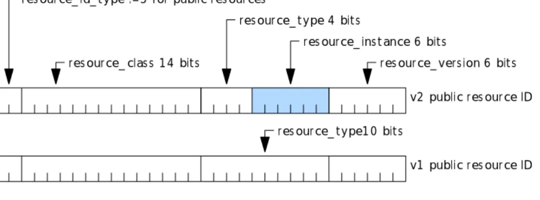
Some of the additional resources identified in "Command Interface - Additional Resources" require a method by which applications can identify a specific instance of a resource amongst several instances of the same resource class. For example, to allow an EPG to discriminate between several identical input modules each connected to a different network. For these new resources this is addressed by allocating the 6 least significant bits of the type field as a resource instance field.
res ource_ id_ t ype !=3 for public res ources
res ource_ clas s 1 4 bit s
res ource_ t ype 4 bit s
res ource_ ins t ance 6 bit s
res ource_ vers ion 6 bit s v2 public res ource ID
v1 public res ource ID
privat e_ res ource_ definer 1 0 bit s privat e_ res ource_ ident it y 2 0 bit s res ource_ t ype1 0 bit s
v1 privat e res ource ID
res ource_ id_ t ype ==3 for privat e res ources
privat e_ res ource_ ident it y 1 4 bit s res ource_ id_ t ype ==3 des ignat es a privat e res ource ID
regis t rat ion_ aut horit y 4 bit field
privat e_ res ource_ definer 1 2 bit field
res ource_ ins t ance ins ert ed here if required by a privat e res ource
v2 privat e res ource ID
Figure 2: Resource ID coding
Instances of the same resource are discriminated by the lower 6 bits of what was previously the resource_type field. Resources discriminated in this way are advertised by modules and the host during the profile enquiry/reply dialogues during initialization. Later, a specific instance of a resource can be accessed by opening a session to the resource with that resource ID in the normal way.
In the set of resources developed in the present document, 3 uses of resource discrimination are seen: 1) discriminating identical resources provided by modules:
- here modules use a host allocated Module ID to fill the resource_instance field of the resources that they declare;
- this case applies, for example, to input modules. Instances of identical input modules, providing connection to different networks by their resource_instance field;
2) discriminating between host and module provided resource instances:
- after the modules have declared their resources (where appropriate using the Module ID in their
resource_instance field) the host can allocate other resource_instance values to discriminate host provided instances of the same resources;
- this case might apply where both the host and modules provide instances of a copy protection resource. The host creates resource_instance values for its copy protection resources to avoid collision with those provided by modules;
3) module specific resource interfaces:
- where a host resource shall provide a specific channel of communication with each module using its services the host can declare a "personal" instance of the resource for each module by using the module's Module ID to in the resource_instance field of the resources it declares;
- this case applies, for example, to the event manager. After the host has determined the set of modules supporting a Module ID the event manager declares an instance each dedicated to one module.
4.2
Establishing the Module ID
Version 2 of the resource manager protocol, in a backwardly compatible way, manages the assignment of a unique identity - Module ID - to each transport connection requiring this functionality.
Module IDs are assigned by the host before resource profiling. They are exhibited by certain resources as part of their resource type field when they declare their resource profile to the resource manager. In this way identical modules presenting identical resources will present distinct resource identifiers. Once assigned, it is recommended that the Module ID is retained by the module in a non-volatile way (i.e. the Module ID is preserved even if power is removed from the module). The host can update the Module ID if required.
The text that follows updates that in subclause 8.4.1 of EN 50221 [5] to describe the behaviour of the version 2 resource manager.
The following resources depend on this enhancement. Hosts and modules that provide or use these resources shall support version 2 of the resource manger:
• input modules; • status query functions; • event management; • copy protection; • CA pipeline resource.
Table 2 identifies the element that shall provide the Module ID in each case:
Table 2: Requirement for Module ID
Resource Resource
Provider
Resource User
Input Modules ✓
Status Query Functions ✓
Event Management ✓
Copy protection ✓
4.2.1
Resource Manager - version 2
The Resource Manager is a resource provided by the host. There is only one type in the class and it can support any number of sessions. It controls the acquisition and provision of resources to all applications. A symmetrical
communication protocol is defined between the module and the host to determine the resources each can provide. The protocol is used first by the host to interrogate each transport connection in turn to determine what resources, if any, are presented for use on that transport connection. Then it is used by applications to find out the total resources available. It is then used periodically when resources change to update the common view of available resources.
The Resource Manager is provided by the host and cannot be superseded by a resource on a module. Any attempt to provide a Resource Manager resource by a module shall be ignored by the host.
4.2.1.1
Resource Manager Protocol
This protocol is in two parts - ModuleID establishment and Resource Profile establishment and notification. The second part is identical to version 1 of the Resource Manager protocol. The first part is a new addition.
When a module is plugged-in, or the host is powered up, one or perhaps two transport connections are created to the module serving an application and/or a resource provider. The first thing an application or resource provider does is to request a session to the Resource Manager resource, using either the version 1 or version 2 variant of the resource ID as appropriate. On successful establishment of the session the Resource Manager sends a Profile Enquiry to the application or resource provider.
Newer modules in older hosts
If a newer module attempts to open a session to the resource manager using the version 2 resource manager resource ID (0x00010042) the standard behaviour of a host that only supports version 1 should be to reply with
open_session_response having session_status = 0 x F2 ("session not opened, resource exists but version lower than requested"). The subsequent behaviour of the module is implementation dependent for example, the module might open a version 1 session to the host and then present a reduced set of resources.
Unless the resource manager has version ≥ 2 the module shall: - omit the Module ID establishment part of the protocol entirely; - not declare resources that depend on the availability of a Module ID.
4.2.1.2
Module ID establishment
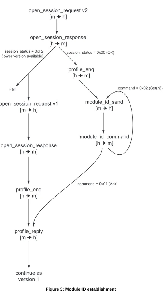
On receiving Profile Enquiry a module respecting version 2 of the protocol shall reply with Module ID Send: 1) if the module already has a previously allocated ModuleID (stored by the module in non-volatile form), it
returns this in the Module ID Send object:
- if ModuleID has not been previously allocated then a ModuleID value of 0 is sent;
2) the Resource Manager replies with a Module ID Command object. If the command field in this object is set to Acknowledgement, then it accepts the ModuleID as allocated and the module then continues with the Resource Profile establishment phase:
- if the command field in the Module ID Command object is set to Set_ModuleID, then the module_id field contains a new ModuleID. The module responds with a further Module ID Send object with the new ID. The host in turn responds with a Module ID Command acknowledgement, and the Profile protocol can continue as before.
If at some later time the host needs to change a ModuleID, it sends Module ID Command to update the ModuleID, expecting a Module ID Send in response, and acknowledging that. For simplicity, the Resource Profile establishment phase after a Profile Change notification from a module shall be preceded by the Module ID establishment phase, but a Profile Enquiry initiated by the module to the Resource Manager never needs it.
Once a Module ID is established for a module by the above procedure, then this ID shall be used in the Resource Type field of all resources which use the Module ID mechanism for distinguishing resource instances.
open_session_request v2
[m
➔
h]
open_session_request v1
[m
➔
h]
profile_enq
[h
➔
m]
profile_reply
[m
➔
h]
continue as
version 1
open_session_response
[h
➔
m]
profile_enq
[h
➔
m]
module_id_send
[m
➔
h]
module_id_command
[h
➔
m]
session_status = 0x00 (OK) command = 0x02 (Set(N)) command = 0x01 (Ack) session_status = 0xF2(lower version available)
Fail
open_session_response
[h
➔
m]
4.2.1.3
Resource profile establishment
Directly following Profile Enquiry in the case of version 1, or following the Module ID establishment phase in the case of version 2, the module sends a Profile Reply listing the resources it provides (if any). The application or resource provider shall now wait for a Profile Change object. Whilst waiting for Profile Change it can neither create sessions to other resources nor can it accept sessions from other applications, returning a reply of "resource non-existent" or "resource exists but unavailable" as appropriate.
When it has asked for profiles on all transport connections and received Profile Replies the host builds a list of available resources. Where resources have a version 2 resource identifier coding (see figure 2) multiple instances of the same class & type of resource are automatically differentiated by their resource_instance.
Those resources which have a version 1 resource identifier coding have no discriminating resource_instance. In this case the following rules from EN 50221 [5] apply:
1) where two or more resources match in both class and type the host keeps the one with the highest version number in its list;
2) where the version numbers match also the host keeps all resources and chooses one at random when a create session request is received for it.
Once the host has built its resource list it sends a Profile Change object on all current Resource Manager sessions, and those applications that wish to can then ask the host for its list of resources using the Profile Enquiry object.
When it receives the Profile Change notification for the first time the application or resource provider can interrogate the host with a Profile Enquiry and receive a Profile Reply with the host's list of available resources. After this first
operation of the Profile Changed protocol the application or resource provider is now free to create or accept other sessions. Its session to the Resource Manager persists to allow further Profile Changed notification by the host from time to time.
If a resource provider wishes to notify a change in the profile of resources it provides, it issues a Profile Changed to the host. The host replies with a Profile Enquiry to which the resource provider replies in turn with its updated resource list. The host processes this and, if this results in any change to the host's own resource list, the host will issue a Profile Changed on all active Resource Manager sessions. The applications can then enquire and receive an updated resource list if they wish.
4.2.1.4
Profile Enquiry
The profile enquiry object requests the recipient to reply with a list of the resources it provides in a Profile Reply object.
Table 3: Profile Enquiry object coding
Syntax No. of bits Mnemonic
profile_enq () {
profile_enq_tag 24 uimsbf
length_field() = 0 }
4.2.1.5
Profile Reply
Table 4: Profile Reply object coding
Syntax No. of bits Mnemonic
profile_reply () profile_reply_tag 24 uimsbf length_field() = N*4 for (i = 0; i < N; i + +) { resource_identifier() } }
Resource identifiers for the minimum set of resources which shall be provided are listed in subclause 8.8 of EN 50221 [5].
Further, optional resources are listed in annexes to EN 50221 [5].
A set of additional resources is defined in the present document in "Command Interface - Additional Resources". Service providers and manufacturers can define additional "private" resources (see subclause 4.3).
4.2.1.6
Profile Changed
The Profile Changed object notifies the recipient that a resource has changed. A module would typically use it to notify the host if the availability status of any of its resources had changed (but not just if a resource was in use). The host would modify its own resource list if necessary, and if there was any change it would in turn send a Profile Changed object on all transport connections.
Table 5: Profile Changed object coding
Syntax No. of bits Mnemonic
profile_changed () {
profile_changed_tag 24 uimsbf
length_field() = 0 }
4.2.1.7
Module ID Send
Send the current ModuleID in response to either a Profile Enquiry, or a Module ID Command updating the ModuleID.
Table 6: Module ID Send object coding
Syntax No. of bits Mnemonic
module_id_send () { module_id_send_tag 24 uimsbf length_field() = 1 reserved 2 bslbf module_id 6 uimsbf } module_id
This is the Module ID allocated and managed locally by the host. Only the 6 least significant bits are used. The two most significant bits shall be set to zero when assigning this value and shall be ignored when reading it. A Module ID of zero shall be used by the module if one has not already been allocated by the host in a previous transaction. A value allocated by the host shall be retained by the module through removal of power.
4.2.1.8
Module ID Command
Sent as an acknowledgement of a Module ID Send object, or to set or update an existing ModuleID.
Table 7: Module ID Send object coding
Syntax No. of bits Mnemonic
module_id_command () { module_id_command_tag 24 uimsbf length_field() = 2 command 8 uimsbf reserved 2 bslbf module_id 6 uimsbf } command
command command value
Acknowledgement 01
Set_ModuleID 02
reserved other values
module_id As defined above.
4.3
Defining and using common interface private resources
4.3.1
Introduction
The Common Interface (EN 50221 [5]) specification provides a capability for defining and using private resources. This subclause:
- modifies the private resource coding defined in EN 50221 [5]; - defines a registration process for private resource identifiers; - describes the technical requirements on private resources.
4.3.2
Defining private resources
4.3.2.1
Registering the resource ID
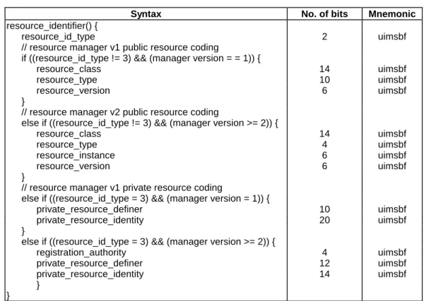
The Resource Identifier is a 32 bit integer. One quarter of the number space is reserved for use by private resources. Table 8 reproduces the resource identifier coding used by resource manager versions 1 and 2 for public resources and private resources (these are also illustrated graphically in figure 2).
Table 8: resource identifier coding format
Syntax No. of bits Mnemonic
resource_identifier() {
resource_id_type 2 uimsbf
// resource manager v1 public resource coding
if ((resource_id_type != 3) && (manager version = = 1)) {
resource_class 14 uimsbf
resource_type 10 uimsbf
resource_version 6 uimsbf
}
// resource manager v2 public resource coding
else if ((resource_id_type != 3) && (manager version >= 2)) {
resource_class 14 uimsbf
resource_type 4 uimsbf
resource_instance 6 uimsbf
resource_version 6 uimsbf
}
// resource manager v1 private resource coding
else if ((resource_id_type = 3) && (manager version = 1)) {
private_resource_definer 10 uimsbf
private_resource_identity 20 uimsbf
}
else if ((resource_id_type = 3) && (manager version >= 2)) {
registration_authority 4 uimsbf private_resource_definer 12 uimsbf private_resource_identity 14 uimsbf } } resource_id_type
This 2 bit field distinguishes the public 75 % of the number space from the private 25 %. Public resource identifiers
resource_class
This 14 bit integer defines the class of a public resource. The set of these identifiers is recorded in EN 50221 [5] and extended in subsequent public extensions to the common interface specification.
resource_type
This field defines related members of a class of resources. For example, in EN 50221 [5] for the class "low speed communications" different values in this field differentiate types of return channel interface (serial port, PSTN modem etc.).
In version 1 of the resource manager 10 bits were allocated to the resource type. In version 2 this field is sub-divided to accommodate the resource instance field.
resource_instance
This 6 bit field reflects the module ID of the providing module for certain types of module provided resource. resource_version
This 6 bit field allows compatibly upgraded versions of public resources to be identified. For example, it identifies the upgraded versions of the resource manager and the application information resource.
Private resource identifiers registration_authority
This 4 bit field identifies the authority that allocates private_resource_definer values to applicants. This field is managed by ETSI. It allows ETSI to delegate authority for managing parts of the range of private_resource_definer values to other registration authorities.
Table 9: Resource identifier registration organizations
value organization
0 ETSI first allocation block, recorded in ETR 162 [3].
1…15 Allocation blocks for future use by ETSI or delegation to other registration organizations, recorded in ETR 162 [3].
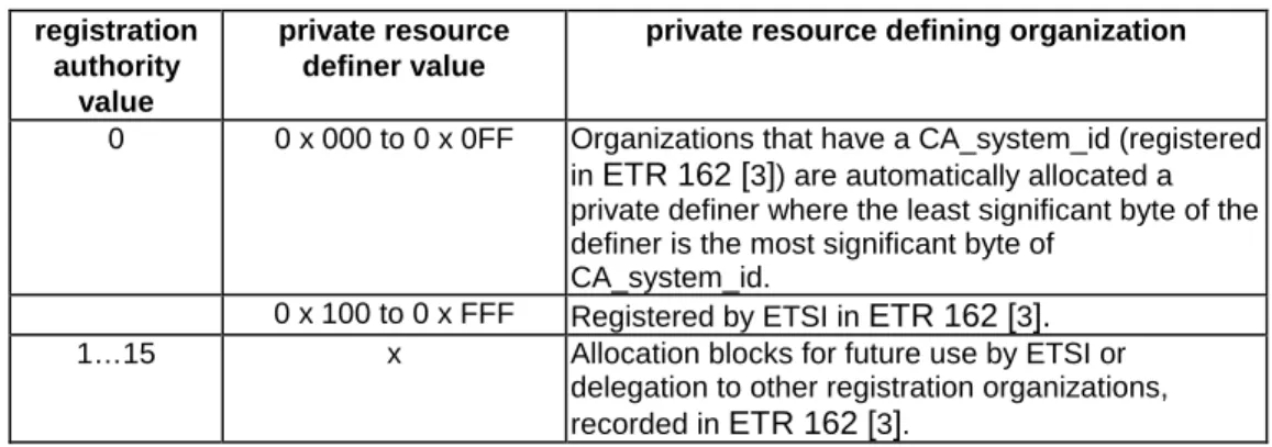
private_resource_definer
This 12 bit field identifies an organization that has obtained registration.
Table 10: Resource identifier registration organizations
registration authority
value
private resource definer value
private resource defining organization
0 0 x 000 to 0 x 0FF Organizations that have a CA_system_id (registered in ETR 162 [3]) are automatically allocated a private definer where the least significant byte of the definer is the most significant byte of
CA_system_id.
0 x 100 to 0 x FFF Registered by ETSI in ETR 162 [3]. 1…15 x Allocation blocks for future use by ETSI or
delegation to other registration organizations, recorded in ETR 162 [3].
private_resource_identity
This 14 bit field is available for private allocation by organizations that have been allocated a private resource definer value. Organizations are not required to publish their use of this number space. See "Use of module IDs".
4.3.2.2
Use of module IDs
As with public resources private resources can use the module ID, allocated to the module by resource manager version 2, to allow different instances of identical modules to be discriminated by an application.
When used, all 6 bits of the module ID shall be used and it shall be inserted in the same position in the private resource identifier as the resource_instance field in a public resource identifier. See figure 2.
4.3.2.3
Resource object definition
The action of all resources is a protocol based on the exchange of objects. Each object comprises a Tag field, followed by a Length field, followed by zero or more bytes of object content. The objects themselves shall be defined, and also the object exchange protocols that implement the resource functionality. The Length field is defined in EN 50221 [5]. For reasons of compatibility with early implementation 3 byte tags shall be used by all resources. The tag values in EN 50221 [5] are globally unique within the specification. This is for historical reasons and new tags defined do not need to be globally unique, only locally unique within one resource.
NOTE: Resource implementors should be aware of this - APDU tags are only unique within a resource. Do not assume that APDU tags will be globally unique.
4.3.2.4
Resource declaration
The entity offering the resource - host or module - shall signal resource availability. This involves notifying the Resource Manager (which runs on the host) of the availability of the resource.
In the case of a module-provided resource, the module shall, on receiving a transport connection from the host, create a session to the Resource Manager resource and participate in the resource profile establishment protocol.
In the case of a host-provided resource, the mechanism will depend upon the particular host environment. By whatever means, the Resource Manager shall acquire a list of all host-provided resources, including any private ones, during the host initialization phase. This could be by static definition of resources at host system build time, or by dynamic means during initialization using an internal protocol or an internal operation of the protocol defined in EN 50221 [5]. Private resources do not have a version field that is known to the Resource Manager so, the version selection protocol used by the Resource Manager for public resources and described in EN 50221 [5] does not apply to private resources. In the case of private Resource Identifier clashes, the Resource Manager will arbitrarily choose one of the conflicting resources to make available in its list. See "Use of module IDs".
NOTE: The "Profile Changed" mechanism (see subclauses 4.2.1.3 and 4.2.1.6) can be used by either module or host to declare resources after the initial resource declaration phase is complete.
4.3.2.5
Access to man machine interface
Applications rather than resources use the MMI. If a module provided resource requires access to the MMI (e.g. to allow user configuration) it should respond to an Application Info Enquiry from the host with an Application Info object presenting an appropriate application type.
4.3.3
Using Private Resources
4.3.3.1
From Modules
Applications running on modules will create a session to the Resource Manager and acquire information about all resources available, including private resources. In order to use a resource, the application shall "understand" the resource protocol. Therefore the application writer shall know both the resource identifier and the protocol specification for the private resource. Beyond that, use of a private resource is identical to use of a public resource - the application creates a session to the resource in the normal manner and then operates the protocol.
4.3.3.2
From Hosts
Hosts may for example provide an API to applications supporting a set of functions such as: - open session request: open a session to a resource;
- close session request: close a session to a resource; - send data: send an APDU on a session; - receive data: receive an APDU on a session.
All the functions shall return state information about the success or otherwise of the operation. These functions are sufficient to provide communication to all resources, however particular host implementations may add extra functionality for reasons of performance or application simplicity. For example, there may be additional functions to give direct access to the Resource Manager's resource database, bypassing the Resource manager protocol defined in EN 50221 [5]. There may also be additional functions giving more direct access to host-based resources, or host-based resources may be used entirely independently of the Common Interface infrastructure. This is entirely the decision of the host designer.
5
Command interface - application information
5.1
Application information - version 2
5.1.1
New application types
Version 2 of the application information resource (with resource ID 0x00020042) extends the set of application_type values that can be coded in the Application Info object. Table 11 defines the extended list.
Table 11: Application type coding
Application type application_type
Conditional_Access 01 Electronic_Programme_Guide 02 Software_upgrade 03 Network_interface 04 Accessibility_aids 05 Unclassified 06
reserved other values
Software_upgrade
Modules that upload software to the host to upgrade the software in the host. No specific upload protocol is implied by this application type.
Unclassified
Modules that don't fall into any other category may be "unclassified".
A new module application type is not usually allocated unless it is likely that a host will have more than one of a type installed.
Audience metering modules are in this type. Network_interface
Any type of input module (including both types 'A' and 'B' described in the present document) can present an application of Network_interface type.
Accessibility_aids
Modules that provide a facility to for those with some form of disability or impairment can use this application type. Audio description modules are in this type.
5.1.2
Unrecognized application type semantics
A host with a version 2 application information resource will understand the full set of application types listed in table 11. When presented with an unrecognized application type they shall treat them as Unclassified (type 06).
6
Command interface - additional resources
6.1
Input modules
Two types of input modules are defined 'A' and 'B'. Type 'A' is a simple, potentially low-cost module for delivery of broadcast services via DVB-C, DVB-S or DVB-T networks to hosts. Type 'B' (see "Type 'B' Input Modules") supports these types of service and in addition allows other types of service and network to be delivered.
6.1.1
Requirements for both input module types
6.1.1.1
TS format
Where the input module delivers a Transport Stream (TS) to the host the TS itself and the data streams within it shall conform to the appropriate DVB specifications for a broadcast TS. In particular:
- TS, PSI, Audio and Video data shall conform to ETR 154 [2]; - SI shall conform to ETS 300 468 [1] and ETR 211 [4].
6.1.1.2
TS control
Input modules shall continue to pass the host supplied TS from its Transport Stream Input to its Transport Stream Output until the host opens a session to the control resource (e.g. StreamInput or ServiceGateway) of the module and sends a command requesting the module to deliver a stream/service (e.g. TuneTSReq or GetServiceReq).
When the host requests the module to stop providing the stream/service or closes the session to the control resource the TS output by the module shall revert to being that supplied by the host.
This requirement does not preclude the module also including CA functions to descramble some or all of the data passing through the module.
6.1.1.3
Input module sessions
Module ID derived resource instances
Each input module shall have a Module ID (see "Extending use of the resource ID type field") and use this ID in the resource ID of the resources that it provides.
The resource ID for type 'A' input modules is of the form 0000 0000 1000 0000 0001 iiii ii00 0001. The resource ID of a type 'B' input module1 has the form 0000 0000 1000 0001 0001 iiii ii00 0001. In each case iiiiii is the Module ID of the input module.
Example
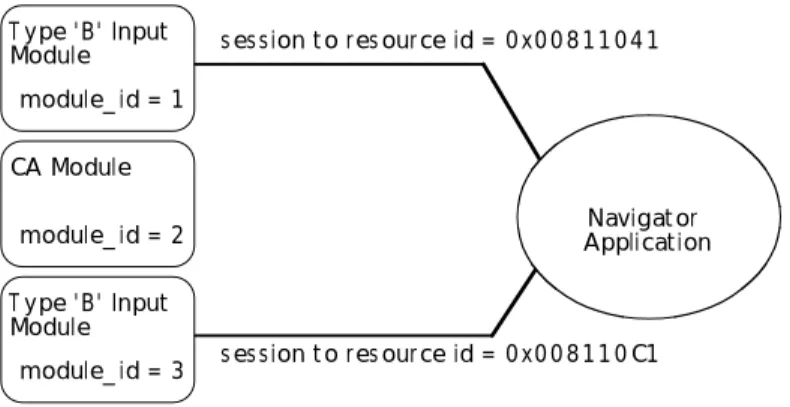
An example is illustrated in figure 14. Here 3 modules are inserted into a host. Two of these modules are input modules which present resource IDs derived from their Module ID. Applications (either host or module resident) can open sessions to each instance of the input module. One module is a CA module which also has a Module ID, but isn't an input module, so doesn't present this type of resource.
T ype ' B' Input Module
module_ id = 1
s es s ion t o res ource id = 0 x0 0 8 1 1 0 4 1
s es s ion t o res ource id = 0 x0 0 8 1 1 0 C1 Navigat or Applicat ion CA Module module_ id = 2 T ype ' B' Input Module module_ id = 3
6.1.2
Type 'A' input modules
6.1.2.1
Introduction (informative)
Module overview
Figure 5 illustrates a possible type 'A' module. Here a low performance microcontroller provides local intelligence within the module. The functions this is will support are:
- user set-up screens, for example, to allow the user to configure a satellite module with regard to the characteristics of the LNB & dish to which it is connected;
NOTE 1: This feature is optional but is likely to be a practical requirement of all real modules. - the ability to search for transport streams;
- the ability to tune to transport streams as directed and then remained locked to them.
<- Module Host ->
T uner Demod Demux
CPU µC
Figure 5: Illustrative type 'A' module
Software model overview Module man machine interface
All input modules shall support host-module communications from the Application Information resource. In particular if a module provides set-up screens these shall be accessible at least in response to Enter Menu message from the host.
Hosts supporting input modules shall provide the user with a method to access the top level menu of each module. Input Set-up
Depending on the delivery system connected to the module it may be appropriate for the module to provide set-up screens, using the normal CI MMI methods, to assist installers set-up the input to the host. For example, these screens might provide display of signal strength to assist antenna pointing etc.
Autoscan set-up
Depending on the delivery system connected to the module it may be appropriate for the module to provide set-up screens to configure its autoscan process. See below.
Host responsibility
The host has no responsibility in these area other than providing a method for the user to activate the top-level user interface screens of the module.
Scanning for TS
The host is responsible for initiating the frequency scanning process. This applies whether module autoscan feature is used or whether the host directs the scanning in a more hands-on way.
Messages are based on delivery system descriptors
The dialogues between the host and the input module are in terms of the payload of DVB SI delivery system descriptors. For all currently defined DVB delivery systems (DVB-C, DVB-S & DVB-T) this payload is the same size (11 byte) but the internal coding varies.
The host is not required to understand this structure to be able to use the module. However, at the host designer's option, enhanced behaviour may be possible where the host does understand it.
Modules shall provide autoscan facilities
All low level input modules shall provide an autoscan function that allows them to search for transmissions. The module is completely responsible for this process. The present document does not limit how this is done. Various approaches can be illustrated that might fit different circumstances:
- the module is initialized by the supplier with a list of frequencies and the attributes of the dish/LNB with which it works:
- this might be appropriate where a service provider or retailer delivers a "shrink wrap" package of module and dish intended to access a particular service provider;
- the module might be supplied pre-initialized with data on the characteristics of various network operators (e.g. Astra and Eutelsat) and various LNB/dishes. The module shall then ask the user to tell it about the circumstances in which it is deployed (e.g. an Acme steerable dish with a Bloggs Inc. "Mark III" LNB);
- the module might provide an "advanced user" set-up. For example, this might provide the user with the ability to configure the method the module should use to select polarization on an LNB (e.g. LNB voltage, 22 kHz tone, DiSEqC, etc.)
Module controlled scanning
The host instructs the module to autoscan. Each time the module "finds" a TS it stops scanning and delivers
TuningInformationMessage (in data equivalent to a DVB SI delivery system descriptor) to the host. TuneTSReq can be used by the host to request that the TS is delivered to the host. So, the host has an opportunity to store the
TuningInformationMessage and to analyse the SI in the TS allowing it to extract service lists etc. Alternatively, the host might just store the TuningInformationMessage and return later to analyse the SI in more detail. The host can tell the module to continue the search. Eventually the module will report "search done".
When the module performs a search for TS the host should not assume that the module has access to the SI within each TS. The host is responsible for analysing the SI in each TS found. For example, in a terrestrial environment the host may be able to get the same TS on more than one frequency. The host is responsible for deciding which set(s) of tuning information to store for each TS.
NOTE 2: It might be useful to store more than one set of tuning information for a TS to accommodate variable reception conditions!
Host controlled scanning
The host can also construct tuning information to instruct the module to tune. In this way the host can control the search strategy. This gives the host an opportunity to take advantage of any special knowledge it might have. For example, it might "know" about a "barker channel" which provides reliable tuning information. This might allow the host to accelerate tuning.
Features of this type are enabled but not required by the present document. They are therefore an area for product differentiation.
Hosts should be aware that the tuning information provided by the NITs on some delivery systems (e.g. SMATV and Terrestrial) can be unreliable.
Storing tuning information
During the TS scanning process the host will potentially discover many TS and services. It is a host implementation choice to decide how many to remember, and the facilities provided to the user for selecting services.
The minimum information that host needs to retain to be able to return to a TS is the tuning information provided by the module and a reference to the module (to identify it in the case that there is more than one input module in the host). To be able to return to a service the host shall at least store the original network ID, the service ID and a reference to the TS holding that service. The quantity of information involved here is likely to be quite modest.
Optionally hosts might store additional information associated with each service such as the service name. TS & Service selection
Tuning to TS
The host can command the input module to tune to a TS. The TS is specified with the standard 11 byte TuningInformationMessage.
Service Selection
The host is responsible for accessing services within each TS. A type 'A' input module is not required to have visibility of the services within a TS.
CA features
Independent of their type 'A' input module functionality, input modules can also provide a Conditional Access Support resource to manage CA access to services within TS. In this case the host communicates independently to the tuning support and the CA support features. Here the host behaviour is almost identical to the case where CA is provided by a separate module down stream of the input module.
6.1.2.2
Type 'A' module command interface
StreamInput
Type 'A' input modules shall present a StreamInput resource to the host. The resource identifier for this resource is 0x00801ii1. This resource shall support a single session.
After a session is opened to its StreamInput resource the module shall continue to pass the host supplied TS from its Transport Stream Input to its Transport Stream Output until TuneTSReq is used to tune to a specified TS when the selected TS replaces the one from the host as the output of the module. The TS output of the module reverts to the TS from the host either when the session to the StreamInput is closed or TuneTSReq is used without a
TuningInformationMessage.
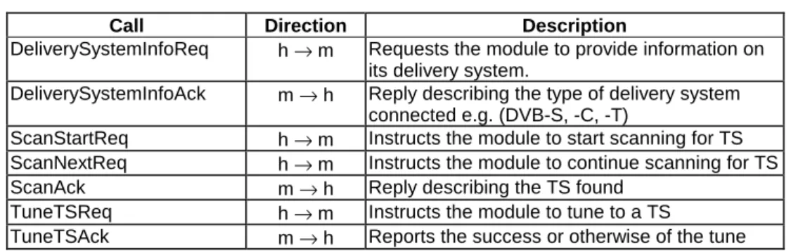
Table 12 summarizes the set of stream level module control calls presented by the StreamInput resource.
Table 12: Overview of the streamInput objects
Call Direction Description
DeliverySystemInfoReq h → m Requests the module to provide information on its delivery system.
DeliverySystemInfoAck m → h Reply describing the type of delivery system connected e.g. (DVB-S, -C, -T)
ScanStartReq h → m Instructs the module to start scanning for TS ScanNextReq h → m Instructs the module to continue scanning for TS ScanAck m → h Reply describing the TS found
TuneTSReq h → m Instructs the module to tune to a TS
DeliverySystemInfoReq
Requests the module to report on the delivery system it connects to.
Table 13: DeliverySystemInfoReq syntax
Syntax No. of bits Mnemonic
DeliverySystemInfoReq () {
DeliverySystemInfoReqTag 24 bslbf
length_field() }
DeliverySystemInfoReqTag
This 24 bit field with value 0x9F8000 identifies this message. DeliverySystemInfoAck
Reply to DeliverySystemInfoReq describing the type of delivery system connected to the module.
Table 14: DeliverySystemInfoReq syntax
Syntax No. of bits Mnemonic
DeliverySystemInfoReq () { DeliverySystemInfoAckTag 24 bslbf length_field() for (i = 0; i < N; i + +) { SystemIdentifier 8 bslbf } } DeliverySystemInfoAckTag
This 24 bit field with value 0x9F8001 identifies this message. SystemIdentifier
This 8 bit field identifies the delivery system(s) connected by the module. The values defined for this field defined in table 15.
Table 15: Delivery system identification
SystemIdentifier value Delivery system Tuning information message format
0 "Abstract" Module specific
1 DVB-C As DVB SI cable delivery system descriptor 2 DVB-S As DVB SI satellite delivery system descriptor 3 DVB-T As DVB SI terrestrial delivery system descriptor > 3 Reserved for future use
The TuningInformationMessage format is in all cases 11 bytes long. In cases 1 to 3 the message is the last 11 bytes of the corresponding DVB SI delivery system descriptor (i.e. all bytes after the descriptor tag and length fields). All other delivery systems shall use the same 11 byte format.
Hosts supporting input modules shall be able to work with all delivery systems (even those not yet defined) as there is no requirement for hosts to understand the tuning information message. The purpose in revealing the type of the delivery system is to enable hosts to provide enhanced facilities for delivery systems with which they are "familiar".
"Abstract" delivery systems
The "abstract" delivery system uses a standard size 11 byte tuning information message. However, the coding of this message is not publicly defined.
Example cases where modules may declare their network as "abstract" include:
- SMATV or small CATV networks where the tuning information delivered by the NIT is not reliable following remodulation of signals from a different delivery system;
- new delivery systems with different modulation parameters. ScanStartReq
Instructs the module to start scanning for TS from some "start point" of its own choosing.
On receiving this the module may open a MMI session to request the user to configure parameters affecting the scope of the search. The host shall be able to let the module open a session to the MMI resource.
Table 16: ScanStartReq syntax
Syntax No. of bits Mnemonic
ScanStartReq () {
ScanStartReqTag 24 bslbf
length_field() }
ScanStartReqTag
This 24 bit field with value 0x9F8002 identifies this message. ScanNextReq
Instructs the module to continue scanning for TS from the "point" achieved when ScanAck last returned.
Table 17: ScanNextReq syntax
Syntax No. of bits Mnemonic
ScanNextReq () {
ScanNextReqTag 24 bslbf
length_field() }
ScanNextReqTag
This 24 bit field with value 0x9F8003 identifies this message. ScanAck
Reply from the module to the host when a broadcast signal is found, or the search is completed. The TS found is not delivered to the host unless a TuneTSReq is sent.
Table 18: ScanAck syntax
Syntax No. of bits Mnemonic
ScanAck () { ScanAckTag 24 bslbf length_field() TSState 8 uimsbf TuningInformationMessage 11x8 bslbf ScanProgress 8 uimsbf } ScanAckTag
TSState
This 8 bit field delivers an unsigned integer indicating the availability of the TS. The coding of this field is as follows: - 0 indicates no signal found:
- when auto-scanning for TS '0' indicates that the auto-scan process has searched all possible frequencies; - 1 to 255 provide a normalized representation of the signal quality (bigger is better).
TuningInformationMessage
This 11 byte field carries a delivery system dependent coding of the tuning information to re-acquire the TS found by the module.
The value of this field is not defined if the TSState is '0'. ScanProgress
This 8 bit unsigned integer provides an approximate proportional indication of how far through the auto-scanning process the module is. The range of allowed values is 0 to 255. The value increases as the scan progresses. TuneTSReq
This call requests the module to tune to the TS using the tuning information supplied. If the TuningInformationMessage field is missing (i.e. the length field indicates zero following bytes) then the request is for the module to disconnect from the network.
Table 19: TuneTSReq syntax
Syntax No. of bits Mnemonic
TuneTSReq () { TuneTSReqTag 24 bslbf length_field() TuningInformationMessage 11 x 8 bslbf } TuneTSReqTag
This 24 bit field with value 0x9F8005 identifies this message. TuningInformationMessage
This 11 byte field carries a delivery system dependent coding of the tuning information to acquire the TS found by the module. The coding is identical to the TuningInformationMessage returned by ScanAck.
TuneTSAck
This reply indicates that the module has tuned to the requested frequency in response to a TuneTSReq. The message is sent when the module is delivering a stable TS.
Table 20: ScanAck syntax
Syntax No. of bits Mnemonic
TuneTSAck () { TuneTSAckTag 24 bslbf length_field() TSState 8 uimsbf } TuneTSAckTag
TSState
This 8 bit field has identical coding to the TSState returned value returned by ScanAck.
In the case that TuneTSReq has no TuningInformationMessage (i.e. the message is "network disconnect") then this field shall have the value '0' (i.e. no signal).
6.1.3
Type 'B' input modules
6.1.3.1
Introduction (informative)
Module Overview
Figure 6 illustrates a possible type 'B' module. This example might be suitable for connections to a broadcast network. In this case the module has a demux and a CPU and hence is able to analyse information about the network (in this case DVB SI) and provide service level access (compared to the TS level access provided by the type 'A' module - see "Type 'A' Input Modules").
<- Module Host ->
T uner Demod Demux
CPU
CPU Demux
Figure 6: Illustrative type 'B' module for broadcast networks
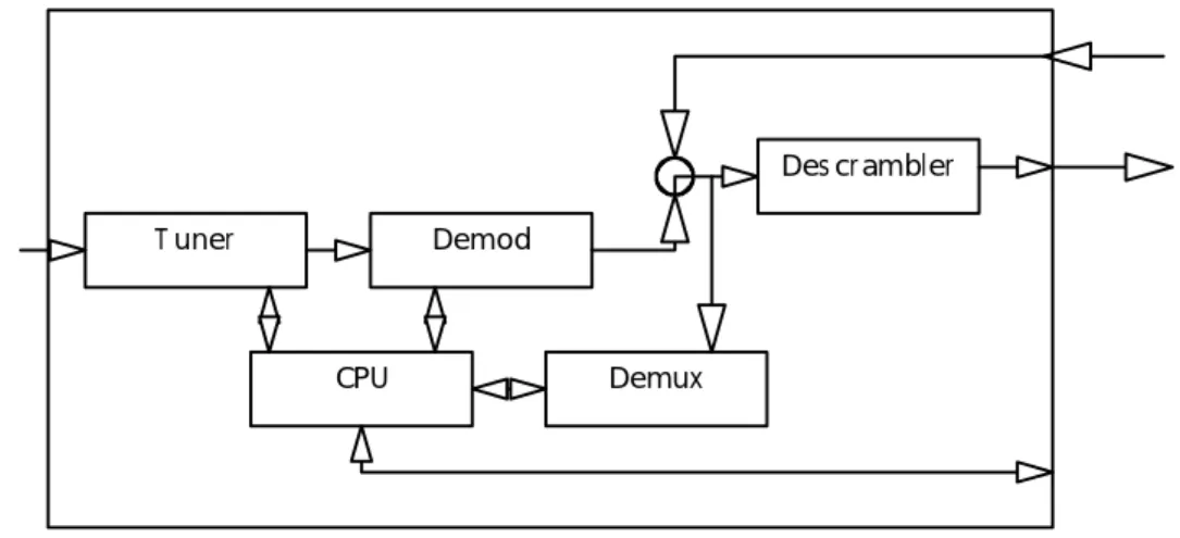
Input modules might also integrate CA functions, in which case figure 7 might be representative of the module functions required.
T uner Demod
CPU Demux
Des crambler
Figure 7: Type 'B' input module with CA
Software Model Overview
This subclause illustrates possible relationships between the type 'B' module and a navigation application. Navigation model
The model assumes that the basic navigation model for hosts with DVB CI is DVB SI. Hence DVB SI service naming concepts are used by the CI to present the list of available services to the host.
This approach can be used to give generic hosts access to a wide range of TV and other services. However, it is
envisaged that in the future this module-host API may evolve and provide new methods that allow "aware" hosts to work more directly with novel service types.
Simple TV access
In figure 8 a basic host accesses normal TV services provided by a module. In this case the module provides a list of the services it can provide. The application presents this list to the user. When the user selects a service the module delivers the service to the host where it is decoded.
Navigat ion Applicat ion S ervice Gat eway Res ource Hos t Module T V S ervice
Decoder T V S ervice S t r eam
Figure 8: The basic host application/gateway resource relationship
The host's "Navigation Application" can be designed to seamlessly integrate the list of module delivered services with the list of "its own" services.
Basic access to new service types
In figure 9 the same basic host is connected to a module that can provide access to new types of service. The module provides a decoder for the service and thus insulates the host from having to "understand" the service. For example, the module might be providing access to a wired VOD service. Here, the module resident "Type Specific Decoder" (TSD) is a "browser" which allows the user to navigate the VOD server. The "browser" is presented to the user via the module-to-host Man Machine Interface routines.
S ervice Gat eway Res ource T ype S pecific Decoder Hos t Module Navigat ion Applicat ion Hos t MMI s ervice reques t s ervice delivery
Figure 9: A basic host accessing more advanced services
In figure 9 the list of services presented by the module includes a service with a new type "Service Gateway". If the user selects this "Service Gateway" service the module activates the TSD. In some cases (e.g. VOD) the TSD allows the user to browse a catalogue. A catalogue selection may result in an MPEG AV stream being sent from the module to the host. In other cases (e.g. home shopping) catalogue browsing may be the end purpose of the TSD.
Aware hosts
In figure 10 a more advanced host is connected to the module (possibly the same module as in figure 9). Here the host "recognizes" new resource types presented by the module and is able to directly take advantage of them.
S ervice Gat eway Res ource + T ype S pecific Ext ens ions T ype Aware
Applicat ion
Hos t Module
T ype S pecific Decoder
Figure 10: An advanced host application accessing advanced services
An example might be where the module provides access to a network file system (implemented using DSM-CC protocols). The Type Specific Extensions in the module could present the file system by means of the DSM-CC U-U API. The TSD in the host might simple be an MHEG-5/6 engine implemented on top of the DSM-CC U-U API. Broadcast Type Specific Resource
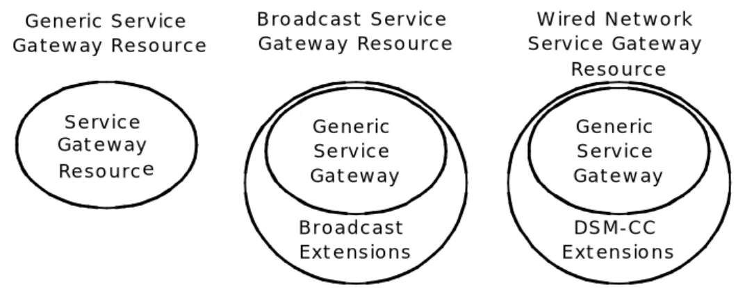
In this initial proposal the facilities of the basic Service Gateway Resource are outlined (see "Service presentation"). In addition a set of Type Specific Extensions appropriate to broadcast TV services are outlined (see "Event Presentation"). These extensions provide information describing the broadcast events which might be of use to host based TV guide. Evolution of extensions
Typically4 Service Gateway Modules will present the Generic Service Gateway Resource on a well known resource ID. In addition, the module can also present a Network Specific Service Gateway Resource which inherits the facilities of the generic resource but extends them with facilities specific to the network.
S e r v i c e G a t e w a y R e s o u r c e G e n e r i c S e r v i c e G a t e w a y R e s o u r c e G e n e r i c S e r v i c e G a t e w a y B r o a d c a s t E x t e n s i o n s B r o a d c a s t S e r v i c e G a t e w a y R e s o u r c e G e n e r i c S e r v i c e G a t e w a y D S M - C C E x t e n s i o n s W i r e d N e t w o r k S e r v i c e G a t e w a y R e s o u r c e
Figure 11: Modules presenting Type Specific APIs
For example, a module providing access to DVB-T broadcasts might also present the variant of the Service Gateway Resource with Broadcast Extensions, allowing it to present event information in addition to service lists.
6.1.3.2
Service presentation
ServiceGateway
Table 21 summarizes the set of "Service Gateway" calls presented by the Generic Service Gateway Resource. These facilities are also inherited by ALL other Network Specific Service Gateway Resources.
After a session is opened to its ServiceGateway resource the module shall continue to pass the host supplied TS from its Transport Stream Input to its Transport Stream Output until GetServiceReq is used to request access to a specified service when a new TS may replace the one from the host as the output of the module. The TS output of the module reverts to the TS from the host either when the session to the ServiceGateway is closed or GetServiceReq is used with no service reference.
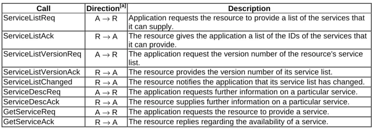
Table 21: Overview of Application ↔ Resource service interface calls
Call Direction[a] Description
ServiceListReq A → R Application requests the resource to provide a list of the services that it can supply.
ServiceListAck R → A The resource gives the application a list of the IDs of the services that it can provide.
ServiceListVersionReq A → R The application request the version number of the resource's service list.
ServiceListVersionAck R → A The resource provides the version number of its service list.
ServiceListChanged R → A The resource notifies the application that its service list has changed. ServiceDescReq A → R The application requests further information on a particular service. ServiceDescAck R → A The resource supplies further information on a particular service. GetServiceReq A → R The application requests the resource to provide a service. GetServiceAck R → A The resource replies regarding the availability of a service.
ServiceListReq
The ServiceListReq can be issued by the host to request the list of service references that the module can provide. Typically this is done when a module is first configured or each time the host observes that the version number of the service list has changed, but it might also be done in response to a "ServiceListChanged" message from a module.
Table 22: ServiceListReq syntax
Syntax No. of bits Mnemonic
ServiceListReq () {
ServiceListReqTag 24 bslbf
length_field() }
ServiceListReqTag
This 24 bit field with value 0x9F8000 identifies this message. ServiceListAck
In response to "ServiceListReq" a module returns a service list version number followed by a list of the service
references that the module can support. These references are persistent as they are either the "real" DVB SI reference to DVB broadcast service or represent a "logical" service that the module can provide.
Changes in the service list presented should represent "significant changes" in the service offering as the host is encouraged to respond by drawing the user's attention to the change.
Table 23: ServiceListAck syntax
Syntax No. of bits Mnemonic
ServiceListReq () { ServiceListAckTag 24 bslbf length_field() VersionNumber 8 uimsbf NumberOfServices 16 uimsbf for (i = 0; i < NumberOfServices; i + + ) { OriginalNetworkID 16 bslbf ServiceID 16 bslbf } } ServiceListAckTag