Annex A
F7048-180128
Small Vessel Navigation Equipment
Technical Statement of Requirements
Revision: 1
ii Published under the Authority of:
Integrated Technical Services Directorate Fisheries and Oceans Canada
Canadian Coast Guard Ottawa Ontario, K1A 0E6
Table of Contents
Document Management ... 1
1.1 Authority ... 1
1.2 Responsibility ... 1
Foreword ... 2
2.1 Purpose ... 2
2.2 Scope ... 2
2.3 Objectives ... 2
2.4 Applicable documents ... 3
2.5 List of Acronyms and Abbreviations ... 4
2.6 Terminology ... 5
General Requirements ... 6
3.1 Operating Environment ... 6
3.2 Direct Current (DC) Power ... 6
3.3 Network and Data ... 6
3.4 Units of Measurement ... 7
3.5 Cabling and Connectors ... 7
3.6 Delivery Locations ... 8
3.7 Documentation ... 8
3.8 System Integration ... 9
MFD Workstation ... 10
4.1 Multifunction Display (MFD) Workstation ... 10
4.2 MFD software ... 11
Instrument Display ... 14
Personal Computer Workstation ... 16
6.2 PC Workstation Processing Unit ... 16
6.3 PC Workstation Display(s) ... 18
6.4 PC Workstation HID controls ... 19
Radars ... 21
7.1 General Radar Requirements ... 21
iv
Autopilot ... 24
9.1 Autopilot ... 24
9.2 Autopilot Processing Unit ... 24
9.3 Primary Autopilot Controller(s)... 26
9.4 Non-Follow Up Lever Autopilot Controller ... 27
9.5 Follow Up Lever Autopilot Controller ... 27
9.6 Autopilot Rudder Feedback Unit ... 28
Ethernet Switch ... 29
10.1 Ethernet Switch ... 29
Electronics Charting System (ECS) Software ... 30
11.1 Requirements ... 30
Training and Commissioning ... 35
12.1 Equipment Maintenance Training ... 35
12.2 Operator Training ... 36
12.3 Commissioning Support ... 38
Appendix 1 Proposed Configuration Drawing ... 39
List of Tables Table 1 - Related Documents ... 3
D
OCUMENT
M
ANAGEMENT
1.1
A
UTHORITYThis document is issued by the Director General, Integrated Technical Services (ITS), CCG’s National Technical Authority under delegation from the Deputy Minister, Fisheries and Oceans and the Commissioner of the Canadian Coast Guard.
1.2
R
ESPONSIBILITYElectronics and Informatics, Shipboard Electronics group, is responsible for: the creation and promulgation of the document; and
the identification of an Office of Primary Interest (OPI) who is responsible for the coordination and the content of the document.
The OPI is responsible for:
validity and accuracy of the content; availability of this information; update as needed;
periodical revision; and
F
OREWORD
2.1
P
URPOSE2.1.1.1 The Canadian Coast Guard (CCG), a Special Operating Agency of the Department of Fisheries and Oceans (DFO), owns and operates the federal government’s civilian fleet.
2.1.1.2 CCG has a requirement for interconnected navigation equipment for small vessels to meet its operational requirements to provide identical, correct, and timely navigation data to CCG personnel at multiple locations on a vessel.
2.2
S
COPE2.2.1.1 The purpose of this Technical Statement of Requirements (TSOR) document is to detail the activities and deliverables associated with the procurement of commercial off the shelf (COTS) navigation equipment for installation on small vessels of the Canadian Coast Guard fleet across Canada. Small CCG vessels are generally categorized by a size of less than 100 gross tonnes and less than twenty (20) meters in length.
2.2.1.2 The installation and maintenance of all equipment, excluding software, will be performed by the Canadian Coast Guard or a contractor of their choosing.
2.3
O
BJECTIVES2.3.1.1 The CCG has a requirement for a Standing Offer Agreement to procure the following navigation equipment to outfit CCG’s small vessels for use in the Atlantic, Central, Arctic and Western regions:
a) Echo sounder modules; b) Autopilot;
c) Instrument display;
d) Multifunction display (MFD) workstations;
e) Personal Computer (PC) workstation including separate processing unit, display(s) and Human Interface Device (HID) controls;
f) Electronics Charting System (ECS) software; g) Ethernet Switch; and
2.4
A
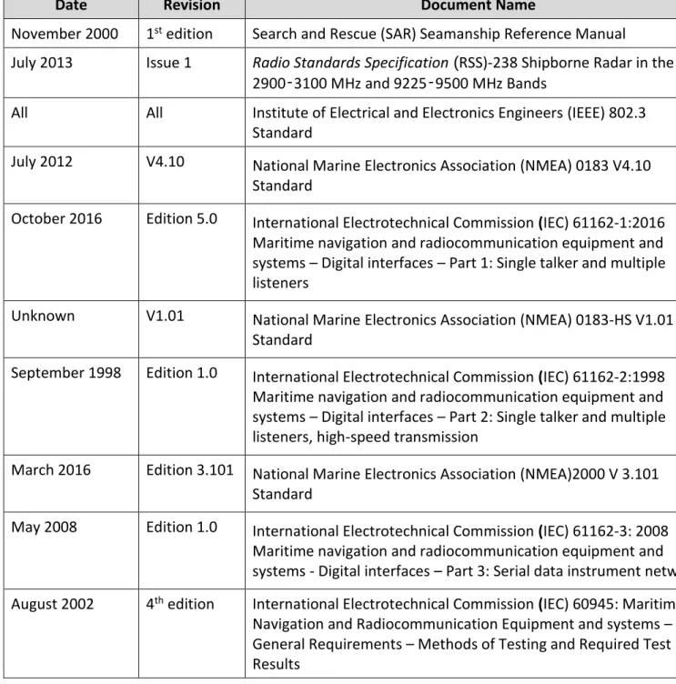
PPLICABLE DOCUMENTSThe following table contains a list of standards to which this document makes reference.
Table 1 - Applicable Documents
International Regulations and Publications (not supplied by CCG) and Government of Canada Acts, Regulations and Publications (not supplied by CCG).
Date Revision Document Name
November 2000 1st edition Search and Rescue (SAR) Seamanship Reference Manual
July 2013 Issue 1 Radio Standards Specification (RSS)-238 Shipborne Radar in the
2900‑3100 MHz and 9225‑9500 MHz Bands
All All Institute of Electrical and Electronics Engineers (IEEE) 802.3
Standard
July 2012 V4.10 National Marine Electronics Association (NMEA) 0183 V4.10
Standard
October 2016 Edition 5.0 International Electrotechnical Commission (IEC) 61162-1:2016 Maritime navigation and radiocommunication equipment and systems – Digital interfaces – Part 1: Single talker and multiple listeners
Unknown V1.01 National Marine Electronics Association (NMEA) 0183-HS V1.01
Standard
September 1998 Edition 1.0 International Electrotechnical Commission (IEC) 61162-2:1998 Maritime navigation and radiocommunication equipment and systems – Digital interfaces – Part 2: Single talker and multiple listeners, high-speed transmission
March 2016 Edition 3.101 National Marine Electronics Association (NMEA)2000 V 3.101 Standard
May 2008 Edition 1.0 International Electrotechnical Commission (IEC) 61162-3: 2008 Maritime navigation and radiocommunication equipment and
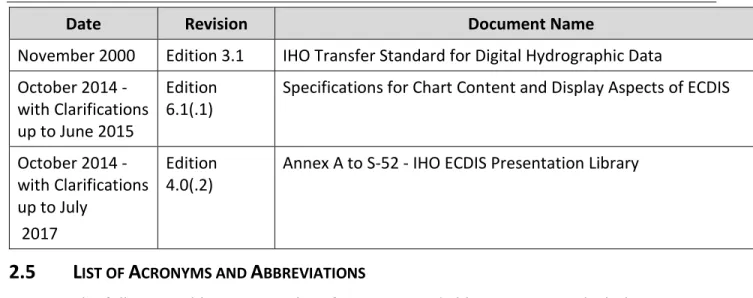
Date Revision Document Name
November 2000 Edition 3.1 IHO Transfer Standard for Digital Hydrographic Data October 2014 -
with Clarifications up to June 2015
Edition 6.1(.1)
Specifications for Chart Content and Display Aspects of ECDIS
October 2014 - with Clarifications up to July
2017
Edition 4.0(.2)
Annex A to S-52 - IHO ECDIS Presentation Library
2.5
L
IST OFA
CRONYMS ANDA
BBREVIATIONSThe following table contains a list of acronyms and abbreviations to which this document makes reference.
Table 2: Acronyms and Abbreviations
Abbreviation Description
AIS Automatic Identification System
CCG Canadian Coast Guard
CHS Canadian Hydrographic Service
COTS Commercial Off the Shelf
CHIRP Compressed High Intensity Radiated Pulse
DC Direct Current
DGPS Differential Global Positioning System GPS
ENC Electronic Navigational Chart
ECS Electronics Charting System
GPS Global Positioning System
HID Human Interface Device
IEEE Institute of Electrical and Electronics Engineers
IEC International Electrotechnical Commission
IHO International Hydrographic Organization
LAN Local Area Network
MFD Multifunction Display
NMEA National Marine Electronics Association
NOAA National Oceanic and Atmospheric Administration
PC Personal Computer
RSS Radio Standards Specification
SAR Search and Rescue
SART Search and Rescue Transponder
TSOR Technical Statement of Requirements
USB Universal Serial Bus
2.6
T
ERMINOLOGYBlack (in relation to screens) means Zero brightness.
Overhead mount means mounted overhead, screen pointing towards the ground or on an angle.
Consistent Common Reference Point means a location on own ship, to which all
horizontal measurements, such as target range, bearing, relative course/speed, closest point of approach, or time to closest point of approach are referenced.
Nits means Measurement of luminance or the intensity of visible light. One nit is equal to one candela per square meter (cd/m2).
Points of Interest means specific pointed locations that can be used to identify noteworthy items such as landmarks.
Radar warm up time means time required for radar to attain operational status. 2.6.7 Route means a sequential series of waypoints linked together in an order in which to
navigate.
2.6.8 Sleeping Automatic Identification System (AIS) targets means targets not moving or at anchor.
2.6.9 Surface mount means a mounting configuration where an item is fit into a cavity in a surface but a portion protrudes slightly and extends beyond the cavity.
2.6.10 Tabletop mount means a mounting configuration where the entire item is mounted onto a horizontal flat surface in an upright position.
2.6.11 Wall mount means a mounting configuration where the entire item is mounted onto a vertical flat surface.
G
ENERAL
R
EQUIREMENTS
3.1
O
PERATINGE
NVIRONMENT3.1.1.1 Navigation equipment components will be installed by Canada on both the enclosed bridge and the fly bridge of CCG vessels as shown in Appendix 1: Proposed
Configuration Drawing.
3.1.1.2 The Contractor must ensure that items shown as located above deck in Appendix 1 are rated at the following minimums:
a) IPX6 or NEMA 4X;
b) Operate within a temperature range of -10 °C to +50 °C unless otherwise specified; and
c) Operate within a relative humidity of 5% to 90%.
3.1.1.3 The Contractor must ensure that items shown as located below deck in Appendix 1 are rated at the following minimums:
a) IP2x;
b) Operate within a temperature range of 0 °C to +50 °C; and c) Operate within a relative humidity of 5% to 90%.
3.1.1.4 The Contractor must ensure that items shown as located above deck, surface mounted in a console in Appendix 1 are rated as follows:
a) The side exposed to the outdoor environment must meet the ratings identified in article 3.1.1.2.
b) The side within the console is exposed to the same conditions as the below deck conditions and must meet the ratings identified in article 3.1.1.3.
3.2
D
IRECTC
URRENT(DC)
P
OWER3.2.1.1 Any equipment that is not powered by the NMEA 2000 network and also requires DC power supplied directly from the ship’s power network:
a) must operate across a range of 12 – 24 VDC plus or minus 10%, excluding the Open Array Radar which must meet the requirement under article 7.2.5.3;
b) should have reverse polarity protection; and
c) should be equipped with a chassis “earth” ground that is isolated from the DC supply.
3.3
N
ETWORK ANDD
ATAbe limited to the following protocols: a) Ethernet as per IEEE 802.3;
b) NMEA 0183 V 4.10 Standard or higher or IEC 61162-1:2016 Maritime navigation and radiocommunication equipment and systems – Digital interfaces – Part 1: Single talker and multiple listeners;
c) NMEA 0183-HS V 1.01 (High Speed) Standard or higher or IEC 61162-2:1998 Maritime navigation and radiocommunication equipment and systems – Digital interfaces – Part 2: Single talker and multiple listeners, high-speed transmission; and
d) NMEA 2000 V 3.101 Standard or higher or IEC 61162-3:2008 Maritime navigation and radiocommunication equipment and systems - Digital interfaces – Part 3: Serial data instrument network.
3.4
U
NITS OFM
EASUREMENT3.4.1.1 Units of measurement displayed for operator use on all workstations and displays must be in accordance with NMEA protocols listed in article 3.3.1.1.
3.5
C
ABLING ANDC
ONNECTORS3.5.1.1 In addition to cabling required in other sections of this document, the following cables must be supplied at a minimum:
a) Except for equipment that has a terminal block intended to be used for power connections, each piece of equipment must be supplied with a matching power cable.
b) Each piece of equipment which supports NMEA 2000 communication and does not have a certified NMEA 2000 connection must be supplied with an adapter which converts whatever connection it uses for NMEA 2000 to a certified NMEA 2000 connector.
c) Each piece of equipment requiring an Ethernet connection to the network switch as shown in Appendix 1 must be supplied with an Ethernet cable that:
i. Has molded connections on each end matching the connection point on the equipment it will connect to;
ii. Is at least 3m long; and
iii. Has an IP rating which matches the equipment it connects to with highest IP rating.
3.6
D
ELIVERYL
OCATIONS3.6.1.1 The Contractor must deliver equipment to any of the following addresses: a) CCG Base, in St. John’s, Newfoundland
Address: 280 Southside Road, St John’s NL, A1C 5X1 b) CCG College, in Sydney, Nova Scotia
Address: 1190 Westmount Rd, Sydney, NS B1R 2J6 c) CCG Base, in Dartmouth, Nova Scotia
Address: BIO Vulcan Building, Rm. V-G42, 1 Challenger Dr, Dartmouth, NS, B2Y 4A2 d) CCG Base, in Dartmouth, Nova Scotia
Address: Door 1A, 13 Akerley Blvd, Dartmouth, NS B3B 1J6
e) CCG Base, in Mont-Joli, Quebec Address: Institut Maurice-Lamontagne, 850 Route de la Mer, Mont-Joli, QC, G5H 3Z4
f) CCG Base, in Quebec City, Quebec
Address: Depot 18, 101 Boulevard Champlain, Québec, QC G1K 7Y7 g) CCG Canada Centre for Inland Waters, in Burlington, Ontario
Address: 867 Lakeshore Rd, Burlington, ON L7S 1A1
h) CCG Electronics and Informatics Workshop, in Sarnia, Ontario Address: 1355 Confederation St, Sarnia, ON N7S 5P1
i) CCG Base, in Victoria, British Columbia Address: 21 Huron St, Victoria, BC V8V 4V9 j) CCG Base, in Victoria, British Columbia
Address: 9860 West Saanich Road, Sidney, BC, V8L 4B2
3.6.1.2 Each item must be packaged in accordance with standard commercial practice. Packaging used must provide a sufficient level of protection to ensure that the contents will arrive safe from damage and that items can be stored in the supplied packaging.
3.7
D
OCUMENTATION3.7.1.1 Each component must be supplied with all manuals required for its installation, service and operation.
3.7.1.2 All documentation must be provided in English or French or both. Any document provided in only one of these languages must also be provided in Microsoft Word format.
3.7.1.3 All instructions and manuals must be supplied in both one hard copy and electronic format with the purchase of each unit.
3.7.1.4 All operator and maintenance manuals must be supplied in searchable Portable Document Format (PDF).
3.7.1.5 Documentation supplied with each component must identify all necessary corrective and preventative maintenance tasks or procedures for that system.
3.8
S
YSTEMI
NTEGRATION3.8.1.1 When assembled in the configuration shown in Appendix 1, all components selected by the Contractor to meet this specification must function as would be expected based on each item’s Operator or User Manual.
MFD
W
ORKSTATION
4.1
M
ULTIFUNCTIOND
ISPLAY(MFD)
W
ORKSTATION4.1.1.1 MFD workstations must be available in two sizes and are identified in Appendix 1 as items 8 and 9. Each MFD workstation must meet all requirements in this Section 4.1. Configuration
4.1.2.1 MFD workstation(s) must incorporate, in a single unit, a processor, display and HID controls necessary to operate the workstation.
4.1.2.2 All HID controls necessary to operate the MFD workstation must be available through non-touchscreen interfaces even if a touchscreen interface is also available.
4.1.2.3 MFD workstation(s) must operate all functions (e.g. change gain) of each of the Radars specified in Section 7 via the Ethernet network or NMEA 2000 network.
4.1.2.4 MFD workstation(s) must operate all functions (e.g. change depth range) of the Echo sounder module specified in Section 8 via the Ethernet network or NMEA 2000 network.
4.1.2.5 MFD workstation(s) must operate the autopilot functions specified in 9.2.4.1 via the Ethernet or NMEA 2000 network.
4.1.2.6 MFD workstation(s) must accommodate surface-mount console installations as well as tabletop and overhead mounting configurations. Each MFD workstation must be supplied with the necessary hardware for tabletop, overhead mounting, and surface-mount installation. This hardware must include weather sealing components (e.g. gaskets) for surface-mount installations.
4.1.2.7 Each MFD workstation must be supplied with the MFD software (see Section 4.2) installed, updated to the latest available version, and include a Device License if applicable.
Dimensions
4.1.3.1 MFD workstation(s) must be flat panel design and have the following minimum display screen dimensions, measured diagonally in inches:
a) MFD Small: 8” b) MFD Large: 12”
4.1.3.2 Including the bezel, MFD workstation(s) must be sized to fit within the following console cavity dimensions in inches (Height X Width X Depth):
a) MFD Small: 11” X 11 ¾” X 8” b) MFD Large: 11” X 15 ¾” X 8”
Performance
4.1.4.1 MFD workstation(s) must have a maximum display brightness of 900 Nits at a minimum.
4.1.4.2 MFD workstation(s) should have a maximum display brightness greater than 900 Nits.
4.1.4.3 MFD workstation(s) must employ optical bonding for anti-reflective and anti-glare screen.
4.1.4.4 MFD workstation(s) display must be adjustable to continuous values between its maximum and minimum brightness (e.g. a knob that turns from black to maximum brightness).
4.1.4.5 MFD workstation(s) “boot up” time in which the system cold starts and goes to completely operationalmode (including loading software and radar warm up time), must be less than or equal to five (5) minutes.
Interfaces
4.1.5.1 MFD workstation(s) must have an Ethernet port to network with other Ethernet connected systems.
4.1.5.2 MFD workstation(s) must include a NMEA 2000 compatible interface to communicate with NMEA 2000 certified sensors.
4.1.5.3 MFD workstation(s) must be NMEA 2000 certified.
4.2
MFD
SOFTWARE4.2.1.1 MFD workstation(s) must be supplied with software pre-installed that meets the requirements of this Section 4.2. This software will be referred to as “MFD software”.
4.2.1.2 MFD workstation(s) must include the feature that provides the capability of controlling the Radar and Echo sounder via Ethernet.
4.2.1.3 MFD workstation(s) must include the following applications: a) Radar;
b) Echo Sounder; and
b) GPS – Route and Waypoint, Vessel Position Data, Course, Speed, Time, Cross Track Error;
c) AIS – Vessel Target Data;
d) Speed Log – Speed and Distance; e) Sounder – Depth and Sea Temperature;
f) Meteorology – Wind Speed(apparent and true), Wind Angle (apparent and true), True Wind Direction, Air Temperature, Humidity, Pressure; and
g) Autopilot – Active route, rudder.
4.2.1.5 MFD workstation(s) must include the feature that allows the users to designate an individual sensor for system use when multiple sensors or data sources of the same type (e.g. DGPS #1 and DGPS #2) are available.
4.2.1.6 MFD workstation(s) must include the features that provide the capability for
communicating with each other when connected to the same Ethernet or NMEA 2000 network to share the following function at a minimum:
a) Navigation sensor information (Radar, DGPS, Compass, AIS, Sounder and Meteorology at a minimum).
4.2.1.7 MFD workstation(s) must support target tracking usingAutomatic Radar Plotting Aid (ARPA) or Mini-automatic radar plotting aid (MARPA).
4.2.1.8 MFD workstation(s) radar application must include the feature that provides the capability for acquiring and automatically tracking a minimum of ten (10) targets within detection range of the radar.
4.2.1.9 MFD Workstation(s) must include the feature that allows the users to access multiple display configurations by selecting among a minimum of two navigation sensor input sources. For example, the display screen can be split with radar and sounder each in their respective section.
4.2.1.10 MFD Workstation(s) must include default display configurations for the echo sounder and the collision avoidance tasks (i.e. radar), each selectable by no more than three (3) operator actions from the other’s display configuration.
4.2.1.11 MFD Workstation(s) must include the feature that allows the operators to select the following radar presentation modes:
a) North Up – display radar image with north direction upwards; and b) Heading Up – display radar image with current vessel heading upwards.
4.2.1.12 MFD Workstation(s) must have a navigation instrument display application which allows the operator to numerically or graphically display the following navigation
information from connected sensors broadcasting NMEA data: a) Compass - True Heading;
b) GPS - Vessel Position Data, Course, Speed, Time, Cross Track Error; c) Speed Log - Water referenced Speed and Distance Travelled; d) Sounder - Depth and Sea Temperature; and
e) Meteorology - Wind Speed (apparent and true), Wind Angle (apparent and true), True Wind Direction, Air Temperature, Humidity, Barometric Pressure.
4.2.1.13 MFD Workstation(s) must a have dayand night mode display setting that changes the display screen colour palette as selected by the operator.
4.2.1.14 MFD Workstation(s) must include the functions that provide the capability for setting proximity AIS target alarms.
4.2.1.15 MFD Workstation(s) must include the functions that provide the capability of filtering alarms to ignore slow moving or stationary or “sleeping” AIS targets.
4.2.1.16 MFD workstation(s) must have manual and automatic gain tuning features to control the Radar.
4.2.1.17 MFD workstation(s) must have automatic clutter suppression techniques to enhance the capability of identifying small targets on the Radar display in a cluttered
environment including ice, sea and rain, without having to manually adjust clutter or gain.
4.2.1.18 MFD workstation(s) must have manual clutter suppression techniques available to the operator to control the Radar display.
4.2.1.19 MFD workstation(s) echo sounder application must include the feature that allows an operator entered offset for depth below keel and depth below water level.
4.2.1.20 MFD workstation(s) echo sounder application must trigger a visual and audible alarm when water depth is shallower than an operator defined level.
I
NSTRUMENT
D
ISPLAY
5.1 The instrument display is identified in Appendix 1 as item 15 and must meet all requirements in this section 5.1.
Configuration
5.1.1.1 The instrument display must operate in a surface-mount configuration.
5.1.1.2 The instrument display must incorporate a display and pushbuttons or dial or both to allow the user to operate the display.
Dimensions
5.1.2.1 Including the bezel, the instrument display must be sized to fit within the following dimensions in inches (Height X Width X Depth): 4 ¾” X 4 ¾” X 2 ½”.
Performance
5.1.3.1 The instrument display must employ optical bonding for anti-reflective and anti-glare screen.
5.1.3.2 The instrument display must have a day and night mode display setting that changes the display screen colour palette as selected by the operator.
5.1.3.3 The instrument display must include the functions that provide the capability of utilizing data from the following sensors at a minimum, in accordance with NMEA 2000 standards listed in section 3.3 Network and Data:
a) Compass – True Heading;
b) GPS –Waypoint, Vessel Position Data, Course, Speed, Time, Cross Track Error; c) Speed Log – Speed and Distance;
d) Sounder – Depth and Sea Temperature;
e) Meteorology – Wind Speed (apparent and true), Wind Angle (apparent and true), True Wind Direction, Air Temperature, Humidity, Pressure; and
f) Autopilot Rudder.
5.1.3.4 The instrument display must include a navigation instrument display application which allows the operator to numerically or graphically display the following navigation information from connected sensors broadcasting NMEA 2000 data:
a) Compass - True Heading;
b) GPS - Vessel Position Data, Course, Speed, Time, Cross Track Error; c) Speed Log - Water referenced speed and Distance Travelled; d) Sounder - Depth and Sea Temperature;
e) Meteorology - Wind Speed (apparent and true), Wind Angle (apparent and true), True Wind Direction, Air Temperature, Humidity, Barometric Pressure; and f) Autopilot Rudder Position.
5.1.3.5 The instrument display must provide default display pages for Compass, GPS, Speed Log, Sounder, Meteorology and Autopilot with each page made available by repeatedly pressing a single push button or turning a dial to scroll through available pages.
5.1.3.6 The instrument display must allow the operator to configure custom display pages that incorporate multiple operator selected data fields from the list of sensors listed in article 5.1.3.4 with an option of at least three (3) data fields.
Interfaces
5.1.4.1 The instrument display must include a NMEA 2000 compatible interface to communicate with NMEA 2000 certified sensors.
P
ERSONAL
C
OMPUTER
W
ORKSTATION
6.1.1.1 The PC workstation configuration must include in separate components: a) HID controls necessary to operate the workstation;
b) display(s); and c) processing unit.
6.2
PC
W
ORKSTATIONP
ROCESSINGU
NIT6.2.1.1 The PC workstation processing unit is identified in Appendix 1 as item 13 and must meet all requirements in this section 6.2.
Configuration
6.2.2.1 The PC workstation processing unit must include proof of compliance with the following testing standard IEC 60945 4th edition: Maritime Navigation and
Radiocommunication Equipment and systems – General Requirements – Methods of Testing and Required Test Results.
6.2.2.2 The PC workstation processing unit must include a solid state storage device for operating system files, at a minimum.
6.2.2.3 The PC workstation processing unit must not have any cooling fan(s).
6.2.2.4 The PC workstation processing unit must include a slot loading DVD drive. If fitted externally, the DVD drive does not impact the PC dimension requirements in article 6.2.4.1.
6.2.2.5 The PC workstation processing unit slot loading DVD drive should be internal.
6.2.2.6 The PC workstation processing unit must operate in a wall-mount configuration and include necessary brackets or mounting tabs.
Operating System
6.2.3.1 The PC workstation processing unit must be supplied with Microsoft Windows operating system pre-installed, with the appropriate device license and with all the latest Microsoft Windows security patches as of the order date of each PC workstation processing unit.
6.2.3.2 Microsoft Windows operating system must be the latest version supported by the Electronics Charting System software specified in Section 11. Only a clean copy of the operating system must be installed on the computer with no third party software other than the drivers specified in article 0.
6.2.3.3 All appropriate hardware drivers must be installed and supplied with the Microsoft Windows operating system.
Dimensions
6.2.4.1 The PC workstation processing unit must fit within the following dimensions in inches (Height X Width X Depth): 5” x 12” x 14.5” inclusive of all mounting hardware.
Performance
6.2.5.1 The PC workstation processing unit must meet or exceed the hardware requirements of the ECS (see section 11) selected by the Contractor.
6.2.5.2 The PC workstation processing unit must have 8 GB of RAM at a minimum.
6.2.5.3 The PC workstation processing unit must have 30 GB of free storage space at a
minimum, after the installation of the PC Operating System and the Electronic Charting System software.
6.2.5.4 The PC workstation processing unit’s “boot up” time in which the system cold starts and goes to completely operational mode, must be less than or equal to five (5) minutes. This includes Windows operating system and Electronic Charting System software specified in Section 11. This excludes login credential input time.
6.2.5.5 The digital video output’s primary and secondary displays, as per article 6.2.6.1, must output video with a refresh rate of 60 Hz and the following display resolutions at a minimum:
a) 4:3 – XGA (1024X768); and b) 16:9 – HD720 (1280X720). Interfaces
6.2.6.1 The PC workstation processing unit must have at least two digitally-compliant (e.g. DVI-D) video output ports which match those on the PC Workstation Display. When one port is set as the primary display, the second port must be capable of mirroring it.
6.2.6.2 The PC workstation processing unit must include at a minimum two (2) internal opto-isolated Recommended Standard -232/422/485 serial ports to interface with NMEA 0183 version 4.10 and NMEA 0183-HS version 1.01 navigation bidirectional sensors transmitting and receiving information.
6.2.6.4 The PC workstation processing unit must include a RJ-45 Gigabit LAN Ethernet port.
6.3
PC
W
ORKSTATIOND
ISPLAY(
S)
6.3.1.1 PC workstation display(s) must be available in three sizes and are identified in Appendix 1 as items 10, 11, and 12. Each display must meet all requirements in this section 6.3.
Configuration
6.3.2.1 PC workstation display(s) must accommodate surface-mount console installations as well as tabletop and overhead mounting configurations. Each display must be supplied with the necessary hardware for tabletop and overhead mounting and weather sealing components (e.g. gaskets) for surface mount console installations required so that it can be mounted in all three off these configurations.
Dimensions
6.3.3.1 PC workstation display(s) must be flat panel design and have the following minimum display screen dimensions, measured diagonally in inches:
a) Small Display: 12” b) Medium Display: 15” c) Large Display: 19”
6.3.3.2 Including the bezel, PC workstation display(s) must not exceed the following dimensions in inches (Height X Width):
a) Small Display: 10 ½”X 12 ½” b) Medium Display: 12 ½” X 15 ¼” c) Large Display: 15 ¾” X 18”
6.3.3.3 Not including the bezel, PC workstation display(s) must be sized to fit within the following console cavity dimensions in inches (Height X Width X Depth):
a) Small Display: 9 ¾” X 11 ¾” X 3 ½” b) Medium Display: 12” X 14 ½” X 3 ½” c) Large Display: 15 ¼” X 17 ½” X 3 ½” Performance
6.3.4.1 PC Workstation display(s) must have a refresh rate of at least 60 Hz.
6.3.4.2 PC workstation display(s) must employ optical bonding for reflective and anti-glare screen.
6.3.4.3 PC Workstation display(s) must be adjustable to continuous values between its maximum brightness and Black (e.g. a knob that turns from black to maximum brightness).
6.3.4.4 PC workstation display(s) must have native display resolutions as follows: a) Small and Medium Display: Extended Graphics Array (XGA) (1024X768) b) Large Display: Super Extended Graphics Array (SXGA) (1280X1024)
6.3.4.5 PC workstation display(s) must have the following maximum brightness output at a minimum:
a) Small Display: 1200 Nits
b) Medium and Large Display: 1500 Nits
6.3.4.6 PC workstation display(s) must be capable of the following contrast ratios at a minimum:
a) Small Display: 1000:1
b) Medium and Large Display: 1500:1
6.3.4.7 PC workstation display(s) should operate within a temperature range of -10 °C to +55 °C.
6.3.4.8 PC workstation display(s) must be equipped with air vents on the back of the unit allowing for ventilation cooling.
Interface
6.3.5.1 PC workstation display(s) must have a digitally compliant (e.g. DVI-D) video input port.
6.4
PC
W
ORKSTATIONHID
CONTROLS6.4.1.1 PC workstation HID controls identified in Appendix 1 as item 14 must meet all requirements in this section 6.4.
Configuration
6.4.2.1 PC workstation HID controls must be an integrated keypad and mouse or pointing device.
6.4.2.2 PC workstation HID mouse or pointing device must include left and right mouse buttons.
Dimensions
6.4.3.1 PC workstation HID keypad must be no larger than the following dimensions in inches (Height X Width X Depth): 1.75" x 16.5" x 8".
Performance
6.4.4.1 PC workstation HID keypad must produce all characters and control functions detailed below, at a minimum:
a) Numeric Characters 0 through 9;
b) Alphabetic Characters A through Z and a through z;
c) Control Keys: Esc, Tab, Ctrl, Alt, Shift, Backspace, Return, Caps-Lock, Num-Lock, Home, Page-Up, Page-Down, End, Ins, Del;
d) Cursor Movement Up, Down, Left, Right; and e) Function Keys F1 to F12.
Interfaces
6.4.5.1 PC Workstation HID Controls must interface with the PC Workstation processing unit via USB.
R
ADARS
7.1
G
ENERALR
ADARR
EQUIREMENTS7.1.1.1 Both the Open Array and Radome Radars specified below must meet the general requirements in this section 7.
7.1.1.2 The Contractor must supply Proof of Certification of transmitting radio-navigation equipment in accordance with RSS-238 by Industry Canada (IC) in the form of a
Technical Acceptance Certificate (TAC) number for each the Open Array Radar and the Radome Radar, issued by the Certification and Engineering Bureau of Industry Canada, or an Industry Canada recognized body.
7.2
O
PENA
RRAYR
ADARS
ENSOR7.2.1.1 The Open Array Radar Sensor must be composed, at a minimum, of the Open Array turning unit (item 1 in Appendix 1) and the Open Array Radar Cable (item 17 in Appendix 1). If it is part of the radar’s design, it must also be supplied with a
corresponding Open Array Interface Unit (Item 2 in Appendix 1). All these components must be designed to work together.
Configuration
7.2.2.1 The Open Array Radar Sensor must operate in the X-Band (9.2 to 9.5 GHz). Dimensions
7.2.3.1 The Open Array turning unit must have an antenna length of four (4) feet plus or minus ten (10) percent.
Performance
7.2.4.1 The Open Array turning unit must have a horizontal beam width of two (2) degrees or less and a vertical beam width of twenty-five (25) degrees or less.
7.2.4.2 The Open Array turning unit must have a nominal output power of six (6) kilowatts (kW) at a minimum if fitted with a magnetron-based transceiver or at least twenty-five (25) watts if fitted with solid-state transceiver.
7.2.4.3 The Open Array turning unit must be compatible with radar beacons and SART triggers operating in the X Band (9.2 to 9.5 GHz) at a distance of one (1) Nautical mile in
Interface
7.2.5.1 The Open Array Radar Sensor must be fully operable via Ethernet by the MFD workstation.
7.2.5.2 The Open Array Radar sensor cable must be ten (10) meters in length plus twenty (20) percent or minus zero (0) percent.
7.2.5.3 The Open Array Radar must operate on 12 VDC plus or minus 10% or 24 VDC plus or minus 10%.
7.3
R
ADOMER
ADARS
ENSOR7.3.1.1 The Radome Radar Sensor must be composed, at a minimum, of the Radome (item 3 in Appendix 1) and the Radar Cable (item 18 in Appendix 1). If it is part of the radar’s design, it must also be supplied with a corresponding Interface Unit (Item 4 in Appendix 1). All these components must be designed to work together. Configuration
7.3.2.1 The Radome Radar Sensor must operate in the X-Band (9.2 to 9.5 GHz). Dimensions
7.3.3.1 X-band radar turning units must be available in Radome form factor with a diameter of nineteen (19) to twenty four (24) inches plus or minus ten (10) percent.
Performance
7.3.4.1 The Radome must have a horizontal beam width within five (5) degrees plus or minus fifteen (15) percent and a vertical beam width within twenty five (25) degrees plus or minus twenty five (25) percent.
7.3.4.2 The Radome must have an output power of two (2) kilowatts (kW) plus or minus fifteen (15) percent at a minimum, if fitted with a magnetron-based transceiver or twenty five (25) watts plus or minus ten (10) percent, if fitted with solid-state transceiver.
7.3.4.3 The Radome Radar Sensor and MFD workstation(s) should provide the capability to scan different radar ranges, near and far, simultaneously, when requested by the operator.
Interface
7.3.5.1 The Radome Radar Sensor must be fully operable via Ethernet by the MFD workstation.
7.3.5.2 The Radome Radar Sensor cable must be ten (10) meters in length plus twenty (20) percent or minus zero (0) percent.
E
CHO
S
OUNDER
M
ODULE
8.1
E
CHOS
OUNDERM
ODULE8.1.1.1 The echo sounder modules are identified in Appendix 1 as item 6 with CHIRP technology and item 7 without CHIRP technology. The echo sounder transducer is shown as item 5 in Appendix 1.. Each echo sounder module must meet the requirements in this section 8.1.
Configuration
8.1.2.1 The Echo sounder module may be incorporated in the MFD workstation described in Section 4. Echo sounder modules not incorporated in the MFD workstation must operate in a wall mount configuration and include necessary brackets or mounting tabs for this installation.
8.1.2.2 The Echo sounder module with CHIRP technology must use Compressed High Intensity Radiated Pulse technology.
8.1.2.3 The Echo sounder module without CHIRP technology must not use Compressed High Intensity Radiated Pulse (CHIRP) technology.
Dimensions
8.1.3.1 No dimensional requirement. Performance
8.1.4.1 The Echo sounder module with CHIRP technology and the Echo sounder module without CHIRP technology must provide the sea floor profile, depth data and sea temperature when connected to an appropriate transducer.
Interfaces
8.1.5.1 The Echo sounder module without CHIRP technology must be compatible with dual frequency through-hull transducers operating at fifty (50) kilohertz plus or minus twenty (20) percent and two hundred (200) kilohertz plus or minus twenty (20) percent with an output power less than or equal to six hundred (600) watts. Echo Sounder Transducers (Appendix 1 item 5) will be supplied by Canada.
8.1.5.2 The Echo sounder module with CHIRP technology must be compatible with through-hull transducers operating at a range of frequencies between forty five (45) to two hundred (200) kilohertz at a minimum with an output power less than or equal to one
A
UTOPILOT
9.1
A
UTOPILOT9.1.1.1 The Autopilot is composed of:
a) Autopilot processing unit and controller distribution box (items 21 and 22 in Appendix 1);
b) Autopilot primary controller(s) (items 23 and 24 in Appendix 1); c) Autopilot lever controllers (items 25 and 26 in Appendix 1);
d) Autopilot hydraulic steering pump drive unit (item 19 in Appendix 1), this item will be supplied by Canada; and
e) Autopilot rudder feedback unit (item 20 in Appendix 1).
9.1.1.2 Where a particular make and model of autopilot is recommended by the manufacturer of the MFD workstation being supplied by the Contractor, this make and model of autopilot must be provided.
9.2
A
UTOPILOTP
ROCESSINGU
NIT9.2.1.1 The autopilot processing unit is identified in Appendix 1 as item 21 and must meet the requirements in this section 9.2.
Configuration
9.2.2.1 The autopilot processing unit must operate in a wall-mount configuration and include necessary brackets or mounting tabs for this installation.
9.2.2.2 The autopilot processing unit must include the functions that provide the capability for connecting to the following number of controllers simultaneously and being operated by any one of them at any time:
a) two autopilot primary controllers (See section 9.3); b) one non-follow up lever controller (see section 0); c) one follow up lever controller (see section 9.5); d) two MFDs via NMEA 2000 (see Section 4) ; and e) one PC computer via NMEA 2000 (see Section 6).
9.2.2.3 If a distribution box (item 22 in Appendix 1) is required to accommodate the number of connected controllers listed in 9.2.2.2 above, it must be supplied with the autopilot
processing unit, including any cables required to interconnect them. Dimensions
9.2.3.1 No dimensional requirement. Performance
9.2.4.1 The autopilot processor must have the following modes of operation, selectable by the operator via the main autopilot controller:
a) Standby Mode – autopilot is on but has no impact on the vessel steering; b) Auto mode – steer the boat automatically on a course set by the operator;
c) Advanced auto mode (No Drift) – maintains a course set by the operator taking the effects of wind, tide and current into consideration in relation to GPS position and compass heading; and
d) Navigation mode – autopilot steers the vessel towards the current waypoint of an active route, taking the effects of wind, tide and current into consideration.
9.2.4.2 The autopilot processor must include a feature to reduce rudder activity and autopilot sensitivity in rough sea states.
9.2.4.3 The autopilot must be designed to operate on vessels up to 20 meters in length. Interfaces
9.2.5.1 The autopilot processor unit must include a NMEA 2000 compatible interface to communicate with NMEA 2000 certified sensors.
9.2.5.2 The autopilot processor unit should include a NMEA 0183 compatible interface to communicate with NMEA 0183 bidirectional sensors, transmitting and receiving information.
9.2.5.3 The autopilot processor unit should be NMEA 2000 certified.
9.2.5.4 The autopilot processor unit must include necessary interfaces to interconnect with the autopilot controllers listed in section 9.2.2.2.
9.2.5.5 The autopilot processor unit must include an interface that can power a direct
reversing 12 VDC, 100 watt hydraulic steering pump drive unit (item 19 in Appendix 1).
9.2.5.7 The autopilot processor unit must include an interface that interconnects with an autopilot rudder feedback unit that provides rudder position data.
9.3
P
RIMARYA
UTOPILOTC
ONTROLLER(
S)
9.3.1.1 The primary autopilot controllers are identified in Appendix 1 as item 23 and item 24. Each autopilot controller must meet the requirements in this section 9.3.
Configuration
9.3.2.1 The primary autopilot controller(s) must operate in a surface mount configuration. Each primary autopilot controller must be supplied with the necessary hardware for surface mount console installations such as weather sealing components (e.g. gaskets).
9.3.2.2 The primary autopilot controller(s) must incorporate a display and HID controls necessary to operate the autopilot.
9.3.2.3 All HID controls necessary to operate the autopilot must be available through non-touchscreen interfaces even if a non-touchscreen interface is also available.
9.3.2.4 The autopilot primary controller must come in two sizes, large and small. The large primary autopilot controller must be comparatively easier to use over the small primary autopilot controller with additional pushbuttons and physically larger push buttons or dial.
Dimensions
9.3.3.1 Including the bezel, the primary autopilot controller(s) must be sized to fit within the following console cavity dimensions in inches (Height X Width X Depth):
a) Small Primary Autopilot Controller: 4 ¾ ” X 4 ¾” X 4 ½” b) Large Primary Autopilot Controller: 5” X 10” X 4 ½” Performance
9.3.4.1 The primary autopilot controller(s) must allow full control of the autopilot and its modes of operation listed in article 9.2.4.1.
Interfaces
9.3.5.1 If the cable required to interconnect the autopilot primary controller to the autopilot processing unit has a molded connection that is not NMEA 2000 compatible, each autopilot controller must be supplied with the appropriate cable that is six (6) meters in length at a minimum.
9.4
N
ON-F
OLLOWU
PL
EVERA
UTOPILOTC
ONTROLLER9.4.1.1 The non-follow up lever autopilot controller is identified in Appendix 1 as item 25 and must meet the requirements in this section 9.4.
Configuration
9.4.2.1 The non-follow up lever autopilot controller must operate in a wall mount or tabletop configuration. Each non-follow up autopilot controller must be supplied with the necessary hardware for a wall mount installation.
Dimensions
9.4.3.1 The non-follow up lever autopilot controller, including any mounting hardware but excluding the lever must be sized to fit within the following console cavity dimensions in inches (Height X Width X Depth): 6” X 6” X 4”.
Performance
9.4.4.1 The non-follow up lever autopilot controller for course steering must incorporate a spring loaded lever that returns to mid position when released. Non-follow up functionality means the rudder is turned to port or starboard as long as the lever is held in either position; the rudder returns the vessel back to its programmed course when the lever is released.
Interfaces
9.4.5.1 If the cable required to interconnect the autopilot non-follow up lever controller to the autopilot processing unit has a molded connection that is not NMEA 2000 compatible, each autopilot controller must be supplied with the appropriate cable that is six (6) meters in length at a minimum.
9.5
F
OLLOWU
PL
EVERA
UTOPILOTC
ONTROLLER9.5.1.1 The follow up remote autopilot controller is identified in Appendix 1 as item 26 and must meet the requirements in this section 9.5.
Configuration
9.5.2.1 The follow up lever autopilot controller must operate in a wall mount or tabletop configuration. Each primary autopilot controller must be supplied with the necessary hardware for wall mount and surface mount console installations; this includes weather sealing components (e.g. gaskets).
in inches (Height X Width X Depth): 6” X 6” X 4”. Performance
9.5.4.1 The follow up lever autopilot controller for course steering must incorporate a lever that turns the rudder to port or starboard in congruence with the lever position. Lever and rudder remain at the commanded angle when the lever is released.
Interfaces
9.5.5.1 If the cable required to interconnect the autopilot follow up lever controller to the autopilot processing unit has a molded connection that is not NMEA 2000 compatible, each autopilot controller must be supplied with the appropriate cable that is six (6) meters in length at a minimum.
9.6
A
UTOPILOTR
UDDERF
EEDBACKU
NIT9.6.1.1 The autopilot rudder feedback unit is identified in Appendix 1 as item 20 and must meet the requirements in this section 9.6.
Configuration
9.6.2.1 The autopilot rudder feedback unit must be supplied with necessary mounting hardware.
Dimensions
9.6.3.1 No dimensional requirements. Performance
9.6.4.1 The autopilot rudder feedback unit must measure and report the rudder position to the autopilot processing unit.
Interfaces
9.6.5.1 The autopilot rudder feedback unit must be selected to function with the autopilot processing unit being supplied by the Contractor.
9.6.5.2 If the cable required to interconnect the autopilot rudder feedbackunit to the
autopilot processing unit has a molded connection that is not NMEA 2000 compatible, each autopilot rudder feedback unit must be supplied with the appropriate cable that is five (5) meters in length at a minimum.
E
THERNET
S
WITCH
10.1
E
THERNETS
WITCH10.1.1.1 The Ethernet switch identified in Appendix 1 as item 16 must meet all requirements in this section 10.1.
Configuration
10.1.2.1 The Ethernet switch (or combination of switches) must have a minimum of six (6) Ethernet ports. The ports may be a connector other than type RJ45.
10.1.2.2 The Ethernet Switch module must operate in a wall mount configuration and include necessary brackets or mounting tabs for this installation.
10.1.2.3 Where a particular make and model of Ethernet switch is recommended by the
manufacturer of the MFD workstation being supplied by the Contractor, this make and model of Ethernet switch must be provided.
Dimensions
E
LECTRONICS
C
HARTING
S
YSTEM
(ECS)
S
OFTWARE
11.1
R
EQUIREMENTS11.1.1.1 The standing offer must include navigation software that can be installed on the PC workstation. This software will be referred to as “Electronic Charting Systems (ECS)”.
11.1.1.2 The ECS must consist of a single application that meets the requirements laid out in this Section 11.1.
11.1.1.3 For each call-up for ECS, the Contractor must supply one perpetual Device Licence for the software, any security device (e.g. dongle) that is required to use the license, and a copy of the ECS installation software on a DVD disc or USB flash drive storage device.
11.1.1.4 The software license must have a current active user base of at least 50 operating vessels over thirty (30) gross tonnes running a recent software release. Recent means any release less than 2 year old. The 50 vessels can be counted as the sum of vessels using any number of software versions released over the last two years.
11.1.1.5 The ECS must include the functions that provide the capability to operate continuously for extended periods of time up to one week without the requirement for a periodic system reboot or application restart.
11.1.1.6 The ECS must provide an indication that the software display screen is being refreshed to ensure the user can be immediately aware of a software lockup. For example, a continuously moving graphic, time displayed in hours: minutes: seconds format, or others.
11.1.1.7 The ECS operational status of navigation sensor information (position, depth and heading at a minimum) must be indicated through the use of colours. For example: red indicates invalid information, yellow indicates low integrity information and green indicates information with good integrity.
11.1.1.8 The ECS must include the following alarmsand alerts at a minimum: a) Crossing depth safety contour;
b) Crossing user selectable boundary area; c) Deviation from route;
d) Approach to oncoming obstacles;
e) Loss of position, heading, AIS system data; f) Chart information over scale;
g) Larger scale ENC or Raster Navigation Charts available; and h) Man Overboard.
11.1.1.9 The ECS alarms and alerts, once activated, must indicate to the user a condition requiring attention through audible or visual means.
11.1.1.10 The ECS must include the feature that allows the users to silence audible active alarms by acknowledging the alarm.
11.1.1.11 The ECS alarms should display the time of alarm occurrence, the cause of the alarm, the source of the alarm and the status of the alarm (acknowledged or not
acknowledged).
11.1.1.12 The ECS must include the functions that provide the capability to install charts for system use from removable USB flash drive storage devices and DVD drives.
11.1.1.13 The ECS must include the functions that provide the capability to utilize ENC vector chart formats released by Canadian Hydrographic Services (CHS), National Oceanic and Atmospheric Administration (NOAA) and other members of the IHO, built to the IHO’s S-57 standard.
11.1.1.14 The ECS presentation of official ENC electronic chart information issued by CHS must comply with or be based upon the colours and symbols recommended for the IHO ECDIS Presentation library in IHO S-52.
11.1.1.15 The ECS must include the functions that provide the capability to utilize Raster Navigation Charts (RNC) produced by CHS and NOAA in a BSB v3 format.
11.1.1.16 The ECS must have a configurable chart loading capability that automatically loads the next en-route chart and displays it in a seamless fashion.
11.1.1.17 The ECS should be capable of automatically loading BSB or S-57, whichever is available while performing the function described in article 11.1.1.16. If both are available, the software should automatically select between the BSB and S-57 while accounting for features which may not be displayed as per article 11.1.1.18.
11.1.1.18 The ECS must include a feature that allows the users to deselect specific charts to prevent their automatic display.
11.1.1.19 The ECS should include the feature that allows the users to apply datum correction to specific charts.
chart marks and navigation objects on the display.
11.1.1.22 The ECS must include the feature that allows the users to add and remove ENC data features from the chart display to provide an uncluttered display of the information needed for safe navigation.
11.1.1.23 The ECS should be capable of saving user configurations using the feature referred to in article 11.1.1.22 as a display mode that can be recalled while route monitoring. 11.1.1.24 The ECS must include a function that will search the removable media described in
article 11.1.1.12 or a selected sub folder of that media for charts which are not currently installed on the ECS and then install new charts and update existing charts as appropriate.
11.1.1.25 The ECS must include the option of securing system administrator settings from unauthorized alteration.
11.1.1.26 The ECS must include the functional measures that provide a means to record all available navigation sensor data and allow for this data to be used for playback on the same PC and other PCs using the same software.
11.1.1.27 The ECS must include the functional measures that provide a means which allows the users to delete recorded navigation sensor data referred to in article 11.1.1.26.
11.1.1.28 The ECS must include the functional measures that provide a means to record voyage tracks.
11.1.1.29 The ECS must include the functional measures that allow to delete recorded voyage tracks referred to in article 11.1.1.28.
11.1.1.30 The ECS should allow the conversion of recorded voyage tracks to routes.
11.1.1.31 The ECS must include a route planning feature allowing the users to plan, document and record the details of a proposed voyage, including the plotting of courses and the marking of points of interest to the voyage.
11.1.1.32 The ECS must include the feature that provides the capability to create a destination point from user provided latitude and longitude coordinates.
11.1.1.33 The ECS must include the function that provides the capability to plot a route with waypoints from the vessel’s location to a destination point created as per article 11.1.1.32.
11.1.1.34 The ECS must include the feature that allows the users to insert waypoints into an existing route and to modify existing waypoint positions.
object vector chart data to determine vessel route safety.
11.1.1.36 The ECS should include the Search and Rescue (SAR) route pattern generation functions referred to in the SAR Seamanship Reference Manual.
11.1.1.37 The ECS must include the functions that provide the capability of importing and exporting routes and waypoints in NMEA 0183, NMEA 0183-HS and NMEA 2000 accepted formats, for example RNN.
11.1.1.38 The ECS must include a route monitoring feature allowing the users to monitor the progress of a voyage in accordance with a planned route, keeping positional track of other items of interest to navigation such as hazards to navigation, ships or points of interest.
11.1.1.39 The ECS mustinclude the functions that provide the capability to incorporate own vessel speed and supply estimated time of arrival to the end of the active route and to the current waypoint.
11.1.1.40 The ECS software must include the functions that provide the capability of using data from the following sensors at a minimum, following NMEA 0183 and NMEA 2000 standards listed in section 3.3 Network and Data:
a) Compass – True Heading;
b) GPS – Route and Waypoint, Vessel Position Data, Course, Speed, Time; c) AIS – Vessel Target Data;
d) Speed Log – Speed and Distance; e) Sounder – Depth and Sea Temperature;
f) Meteorology – Wind Speed (apparent and true), Wind Angle (apparent and true), True Wind Direction, Air Temperature, Humidity, Pressure;
g) VHF DSC – DSC Calling Information; and
h) MFD – Radar Tracked Target Information, Route Plan and Waypoint Information, Active Route Monitoring.
11.1.1.41 The ECS must allow the users to designate an individual sensor for system use when multiple sensors or sources of the same type (e.g. DGPS #1 and DGPS #2) are
available.
vessel reference point for target range and bearing, closest point of approach, etc. 11.1.1.44 The ECS should include the function that provides the capability of displaying forty
(40) AIS targets at a minimum.
11.1.1.45 The ECS should include the functionality that provides the capability to fuse Radar tracked targets and AIS targets to avoid presentation of two (2) target symbols for the same physical target.
11.1.1.46 The ECS must include the functionality that provides the capability of setting proximity AIS target alarms.
11.1.1.47 The ECS should include the functionality that provides the capability of filtering proximity AIS target alarms to ignore slow moving and stationary or “sleeping” AIS targets.
11.1.1.48 The ECS must allow operators to select the following chart presentation modes: a) North Up – display chart with north upwards;
b) Heading Up – display chart with vessel heading upwards; and
c) Course Up – display chart with next waypoint of active route upwards.
11.1.1.49 The ECS navigation instrument display application must allow operators to numerically or graphically display the following navigation information from
connected sensors broadcasting NMEA data in a user configurable information box: a) Compass - True Heading;
b) GPS - Vessel Position Data, Course, Speed, Time, Cross Track Error; c) Speed Log – Water Reference speed and Distance Travelled; d) Sounder - Depth and Sea Temperature; and
e) Meteorology - Wind Speed (apparent and true), Wind Angle (apparent and true), True Wind Direction, Air Temperature, Humidity, Barometric Pressure.
11.1.1.50 The ECS must have a day and night mode display setting that changes the display screen colour palette, as selected by the operator.
11.1.1.51 The ECS should interface with radar sensors specified in Section 7 and overlay radar information scaled to fit the active chart, when selected by the operator.
T
RAINING AND
C
OMMISSIONING
12.1
E
QUIPMENTM
AINTENANCET
RAINING12.1.1.1 The Contractor must provide a customized Equipment Maintenance Training courseto the electronics maintenance staff of CCG, all of whom are qualified, experienced electronic technicians and technologists. The course must meet all the criteria in this section 12.1.
12.1.1.2 The Contractor must create the Equipment Maintenance Training course within 4 months of receiving the first signed call-up for Equipment Maintenance Training. The course must be developed on the basis that a functioning mock-up of the assembly shown in Appendix 1 will be made available by CCG at the location of the course. 12.1.1.3 The Contractor must provide the Equipment Maintenance Training with a minimum
lead time of 8 weeks upon acceptance of the call-up.
12.1.1.4 Class size must be up to eight (8) students.
12.1.1.5 The course must be scheduled for normal business hours with a maximum of six and one half (6.5) hours of class time per day. Training times and dates will be mutually agreed within a notice period of 60 calendar days.
12.1.1.6 The course must cover the following topics at a high level:
General operation of the MFD; and
General operation of the ECS software.
12.1.1.7 The course must cover the following topics in detail:
Installation and maintenance of each piece of equipment listed in Appendix 1 (equipment that comes in multiple sizes, for example PC displays, are only required to be presented once);
Administrator and configuration functions on the MFD; and
Chart installation, administrator and configuration functions on the ECS.
classroom so that the trainer can prepare accordingly.
12.1.1.10 The instructor must have at least three (3) years’ experience servicing this type of equipment.
12.1.1.11 The course must be available in both of Canada’s official languages, French and English. The choice of language for the course must be at the discretion of CCG.
12.1.1.12 Any training materials or documentation produced must be provided in accordance with the language of the given course.
12.1.1.13 The Contractor must seek acceptance from Canada for the course content.
Acceptance means that the item is submitted to the Project Manager for review and the Contractor is required to modify the item as per Canada’s comments before proceeding. The following milestones must be met by the Contractor:
A draft of the course outline must be accepted by Canada before the course is developed;
The final version of any course material, including any presentation slides, must be accepted by Canada; and
After the first course is given by the Contractor, feedback from Canada must be used to update the course if required.
12.2
O
PERATORT
RAINING12.2.1.1 The Contractor must provide a customized ECS Operator Training course to the operations staff of CCG, all of whom are qualified, experienced shipboard navigators. The course must meet the requirements in this section (12.2).
12.2.1.2 The Contractor must create the Operator Training course within 4 months of receiving the first signed call-up for Operator Training.
12.2.1.3 The Contractor must provide the Operator Training with a minimum lead time of 8 weeks upon acceptance of the call-up.
12.2.1.4 The Contractor must deliver the Operator Training with hands-on software usage by all students simultaneously so that they can try all the functions being described by the instructor where possible. Canada will provide each student with a laptop in advance of the training date for use during the training session; if the Contractor requires any software to be installed onto the laptops in advance of the training date (e.g. sandbox version of the software), they must provide this software to the students at no
additional cost.
12.2.1.5 Class size must be up to ten (10) students.
12.2.1.6 The training course must be scheduled for normal business hours with a maximum of six and one half (6.5) hours of class time per day. Training times and dates will be mutually agreed within a notice of 60 calendar days.
12.2.1.7 The Operator Training course must cover the following topics in detail, at a minimum: ECS Software Overview;
Chart installation and maintenance;
Voyage planning;
Navigation sensor (GPS, Gyro, AIS, etc.) management and usage within the ECS;
Chart display configuration, including how to show and hide layers of S-57 charts; and
f) Voyage monitoring, including chart usage.
12.2.1.8 The course length must be at the maximum three (3) working days.
12.2.1.9 The course must be available at each CCG location listed in article 3.6.1.1 other than d) and j). Differing audiovisual equipment is available at each CCG location in the
classroom. The Contractor must coordinate with the point of contact listed on the training call-up to confirm which audiovisual equipment is available at the designated classroom so that the trainer can prepare accordingly.
12.2.1.10 The instructor must be a representative from the ECS software developer.
12.2.1.11 The course must be available in both of Canada’s official languages, French and English. The choice of language for the course must be at the discretion of CCG.
12.2.1.12 Any training materials or documentation produced must be provided in accordance with the language of the given course.
12.2.1.13 The Contractor must seek acceptance from Canada for the course content.
Acceptance means that the item is submitted to the Project Manager for review and the Contractor is required to modify the item as per Canada’s comments before
accepted by Canada; and
After the first course is given by the Contractor, feedback from Canada must be used to update the course if required.
12.3
C
OMMISSIONINGS
UPPORT12.3.1.1 The Contractor must supply, upon Call-up, a specialized technician who will provide one day (no longer than 8 hours) of on-site commissioning support to an installation of equipment that was completed by CCG.
12.3.1.2 The commissioning support must include:
Verification that the system was installed in accordance with each component’s manufacturer recommendations;
Troubleshooting in the case that a device or software is not functioning as expected. Troubleshooting must be provided until the issue is resolved or an agreed upon resolution plan is put in place;
A question period where CCG technicians may ask questions about the equipment to better understand its functions. For questions that cannot be answered during this period, the Contractor’s envoy must follow-up with a response within 5 business days after the commissioning support is complete.
12.3.1.3 The commissioning support must be available at each of the locations listed in article 3.6.1.1 other than d) and j).
12.3.1.4 The specialized technician providing commissioning support must have at least three (3) years’ experience servicing this type of equipment.
Appendix 1
Component List
Item Number Item Name Qty
1 Open Array Turning Unit 1
2 Open Array Interface Unit 1
3 Radome Radar Sensor 1
4 Radome Interface Unit 1
5 Echo Sounder Transducer 1
6 Echo Sounder module with CHIRP technology 1
7 Echo Sounder module without CHIRP technology 1
8 MFD Small Workstation 1
9 MFD Large Workstation 1
10 PC Small Display 1
11 PC Medium Display 1
12 PC Large Display 1
13 PC Workstation Processing Unit 1
14 PC Workstation HID Controls (PC Keypad and Pointing device) 1
15 Instrument display 1
16 Ethernet Switch 1
17 Open Array Radar Cable 1
18 Radome Radar Cable 1
19 Autopilot Hydraulic Steering Pump Drive Unit 1
20 Autopilot Rudder Feedback Unit 1
21 Autopilot Processing Unit 1
22 Autopilot Distribution Box 1
23 Autopilot Small Primary Controller 1
24 Autopilot Large Primary Controller 1
25 Autopilot Non Followup Lever Controller 1
26 Autopilot Followup Lever Controller 1