ЗАЛІЗНИЧНА КОЛІЯ
UDC 625.14:656.2.022-185.4
D. M. KURHAN
1*1*Dep.«Track and Track Facilities», Dnipropetrovsk National University of Railway Transport named after Academician
V. Lazaryan, Lazaryan St., 2, Dnipropetrovsk, Ukraine, 49010, tel./fax + 38 (056) 373 15 42, e-mail [email protected], ORCID 0000-0002-9448-5269
FEATURES OF PERCEPTION OF LOADING ELEMENTS OF
THE RAILWAY TRACK AT HIGH SPEEDS OF THE MOVEMENT
Purpose. Increase the train speeds movements requires not only the appropriate technical solutions, but also me-thodological-calculated. Most of the models and methodologies used for solving problems of stress-strain state of the railroad tracks, are based on assumptions and hypotheses adequate only for certain speeds. In the framework of this work will be discussed theoretical background of the changing nature of perceptual load elements of the railway track at high speeds and investigated the numeric parameters of the processes by means of mathematical modeling. As a practical purposes is expected to provide the levels of train speed, the boundaries of which can reasonably exclude the possibility of occurrence of the considered effects. Methodology. To achieve these objectives was used principal new model of railway track based on wave propagation theory stresses in the elastic system to study the impact of the mov-able load, take into account that the deflection in a particular section of the road starts even while the wheels at some distance, and moving the wheels farther from the selected section of the wave front elastic strain continues to spread. According to the results of simulations explores the changing shape of the wave front voltages in time for the founda-tion under the rail. If the train speeds substantially less than the velocity propagafounda-tion of elastic waves, the wheel re-mains in the area implemented deformations. Findings. Alternative calculations for various parameters of the railway track (especially for different soil conditions) determined the levels of train speed, the boundaries of which can rea-sonably exclude the possibility of occurrence of the considered effects. Originality. The proposed theoretical study and implementation in the form of mathematical models for processes that occur in the perception of load elements of the railway track at high speeds. Practical value. According to simulation results obtained levels of speeds, which define the appearance of the considered dynamic effects in the base under the rail, can be used to justify path construction or establishment of appropriate values of allowable velocities for the implementation of traffic at high speeds.
Keywords: superstructure; high-speed movement; tension of rail; rail deflection; wave model; slab track; ground distortion
Introduction
The steady tendency of transport developments networks demands from railway transport to keep and improve a current state for competitiveness preservation. One of the main indicators of a choice of transport mode traditionally remains the speed of cargo and passengers delivery [9].
The increasing of train speeds service demands not only the appropriate technical means, but also
methodological-calculated. Many models and the techniques which are used for the solution of strain-stress state tasks of a railway track based on assumptions and hypotheses adequate only for cer-tain levels of speed movement.
Time for reaction directly depends on speeds of distribution of elastic waves in material of the cor-responding element of a track. It is clear that in cases when the loading speed (the movement of the train) of one level with a reaction speed, processes of interaction get significantly others looked in comparison with static loading. Considering that for the majority of materials from which the rail-way track consists, speeds of distribution of waves considerably exceed opportunities even modern high-speed trains, this question didn’t demand at-tention. But today this thought changes on oppo-site, especially, as far as concerns railway tracks on soft grounds in which the speed of distribution of waves isn’t so great. In some works even the term «soil blow» by analogy to sound blow started ap-pearing [11, 14].
So at the site of the railway that runs along the waterfront Stilton in the UK recorded a sharp change deflection of the rail at speeds of 180 km/h. The explanation was found in the presence of bal-last in soft soils such as peat and silty clay [15].
In the Netherlands, the area between Amster-dam and Utrecht conducted tests for measuring the velocity of wave propagation in the soil for the possibility of passing the French TGV train speeds over 160 km / h in areas with mounds, consisting of weak soils [15].
In the south-west Sweden in Gothenburg, Malmö site speed train X2 000 was limited to 160 km / h in wave phenomena in the soil [13].
The presence of certain problems of railway track on weak soils is noted on some railroad of Hungary [12].
The issue of delay appearance of rail deflection at high speeds went up in the Austrian authors [3], where, in addition to theoretical considerations, experimental evidence shows the results corre-sponding effects on test plots near Vienna at speeds over 230 km / h.
Purpose
The theoretical prerequisites of emergence of effects of «soil blow» are considered within this work and numerous parameters of process by means of mathematical modeling are investigated. As the practical purpose it is supposed to provide equal train service speeds within which it is possi-ble to exclude possibility of emergence of the spe-cified effects reasonably.
Methodology
Most current models of stress-strain state of railway track, usually based on the principles of static elasticity. It is assumed that the considered system of bodies in a state of equilibrium and elas-tic deformation under the applied force immedi-ately reach respective values. It isn’t enough such approach for tasks in which time between the mo-ment of the appendix of loading and establishmo-ment of true balance it is comparable with time of action or change of loading. It doesn’t correspond to that on a task and the method of final elements which was widely adopted recently including for model-ing of a railway track: it doesn’t give the chance to receive full four-dimensional model.
For the solution of these objectives essentially new model of railway track based on the wave the-ory of tension distribution in system of elastic bod-ies [1, 2, 8] was used. For creation of such model the railroad is considered as spatial system of ob-jects which are characterized by the geometrical sizes and physical properties determining speeds of distribution of waves and parameters of deforma-tions of elasticity and shift. The emergence and distribution in a body of object of spatial spherical waves is considered as a reaction to action of ex-ternal forces. Distribution of waves is corrected by the extent of objects and considers changes in pa-rameters of wave process upon transition from one object to another, and also emergence of the re-flected waves from borders of contacts. The com-mon decision of the equations describing position of the front of a wave at the moment of time, and the equations defining change of potentials of ten-sion in a body of objects taking into account dy-namic deformation of material is result. Such ap-proach gives the chance with a certain temporary in interval to define borders of distribution and value of tension and deformations.
Let’s consider the process of forming a deflec-tion of the rail on the example of modeling a sud-den application of force to the wheels on the rails. Initially there clutching the rail voltage, but very fast (about 0.03rd-ms) are transmitted to the
sub-strate and then to sleepers. At 0.09th ms and inten-sity of ties begin to be transferred to the ballast. Almost at the same time (0.1st ms) load transferred
rail and provides the beginning of the bend. At 0.3rd ms and tie is already full contact with the bal-last to half its length, given as sole sleepers, and its lateral surface. Ballast begins to contract, making it possible to extend the rail curve. During the transi-tion from the front tension ties to the ballast area of interaction will vary over time (increase from point to the entire surface of the sole sleepers).
From the first moment of this interaction strain will be distributed in the thickness of ballast, but the speed distribution over the surface of the bal-last will be significantly less than the growth rate of the area on which the stress transferred from sleepers on ballast. This leads to more complex shapes of the wave front in comparison to the clas-sical description of distribution as two-axial. De-pending on the thickness, condition, physical prop-erties of matter ballast, etc., by 1.0…1.8 ms and tensions begin to be transmitted to the roadbed. With the growth and proliferation of elastic con-traction in roadbed is at last re-stresses between the layers of sub rail basis and in another passage of some time, depending on the properties of the soil, rake up the final parameters of bending.
Thus, the deflection of a rail is provided with deformation of all layers of which the sub rail basis consists. It must be kept in mind that for a «full» deflection of a rail of deformation of a sub rail ba-sis have to gather the corresponding values not only directly on a vertical shaft of application of force, but also on all length of a lath, it is attracted to a deflection. Depending on the module of elas-ticity of a sub rail basis length of a notable deflec-tion of a rail makes some meters.
According to the velocity propagation of elastic waves, eventually increasing depth sub rail basis, which is involved in the formation of deflection rails, but on the other hand, the deformation depth decreases rapidly reduce their impact on the over-all deflection. Furthermore, even already gained significance in certain strains depth marks do not remain constant over time, and are oscillatory (al-though aimed at damping) character. All this com-plicates the criterion for determining such esti-mated moments when we can assume that the de-flection rails gained full implementation.
In the numerical calculations fixed deformation of sub rail bases on several axes adjacent sleepers - the points of coincidence rail deflection and de-formation sub rail bases. By bending the rails, as a reference value, determined by the modulus of
elasticity sub rail base. If further development de-flection changed the modulus of elasticity no more than 5%, it is conventionally recorded acquiring «full» deep.
The change in the wave front of outline stresses in railway track on the simulation results for the soil deformation modulus of 25 MPa is shown on figure 1. The vertical axis on figure coincides with the axis of application of force. The last line shows the time to 26.5 ms after the date of application of the load, for this example corresponds to the condi-tion «full» defleccondi-tion rails.
For the example figure 2 shows the relationship of the analytical rail deflection by the formula (1) [4, 5] and deflections of sub rail bases axes sleep-ers on the results of modeling for steady state
(
cos
sin
)
2
kxPk
z
e
kx
kx
U
−
=
+
, (1)where
P
– the vertical force operating on a batten;k– coefficient of relative stiffness; U – elastic modulus of sub rail basics; x– distance along the length of the rails from the point of force applica-tion.
-4.5 -4 -3.5 -3 -2.5 -2 -1.5 -1 -0.5 0
4 3.5 3 2.5 2 1.5 1 0.5 0
P
26,5 ms
1 ms
sleepers' axle
10 ms
2 ms0
sleeper the distance from the point of force application, m
sole
su
bg
rad
e
de
pt
h r
el
at
ive
to
th
e
sol
e sleep
ers,
m
Fig. 1. Outline of the wave front in sub rail space
2 1
the distance on rail from the point of force application, m
de
fl
ec
ti
on
, m
m
0 0.5 1 1.5 2 2.5 3 3.5
0 0.5 1 1.5 2 2.5
Fig. 2. Change the trough length:
If to consider conveyances of loading (the movement of a wheel) on a rail, it is incorrect to describe process of a deflection of a lath in section from zero to maximum value, preceding from the assumption what exactly is in this section a wheel all the time of development of a deflection. For probe of a certain section of track, it is necessary to consider that the deflection in it begins in the wheel time spent for some distance. At the move-ment of a wheel further from the chosen section the front of a wave of elastic deformation contin-ues to extend. In a case when the speed of the movement of the train is significantly less than a speed of distribution of elastic waves, the wheel always remains in a zone of the realized deforma-tions.
If to enter designations:
A x
( )
– set of points of a half-space are limited to the front of a wave suf-ficient for realization of a «full» deflectionz
п in the point x;B x t
( , )
– set of points of a half-space are limited to the front of a wave after its distribu-tion relativelyA x
( )
on timet
, so between run-ning speed, at get on «full» deflection, will be de-fined by reference( )
п:(
)
(
,)
z V =z A x Vdt+ ∈B x dt . (2)
The example of calculation by reference (2) for relative exaggerate value dx is shown on fig. 3. At running speed
V
1 (line 2) the bending deflection have time to form completely and at speedV
2 (line 4) do not have time.-4 -3.5 -3 -2.5 -2 -1.5 -1 -0.5 0 4 3.5 3 2.5 2 1.5 1 0.5 0
V dt1 V dt2
2 1
3 4
dep
th
re
la
ti
ve
to
th
e s
o
le
s
le
epe
rs
, m
x, м
Fig. 3. Outlines of a wave fronts:
1 –
A
(0)
; 2 –A V dt
(
1)
; 3 –B
(0, )
dt
; 4 –A V dt
(
2)
Thus, calculations show that the movement with so high speeds can take place; the bending deflection of a rail won’t be able to manage to reach the values expected behind static schemes. Perhaps that is said about these processes, for ex-ample, in [3]. However, it is still too large such speed, even larger than the transverse velocity of wave propagation in the soil. This is explained by the redistribution quickly load ground work first ties, and ballast. In a number of works ([12, 13, 15]), on the contrary, growth of bending deflec-tions of a rail at the movement with speeds is shown the big just cross wave speed in the soil.
To show an explanation of this process, it is possible on the static circuit. As a rule, the theo-retical part of tension calculations and deforma-tions in ballast and a road bed is based on decisions of Bussinsk, Flaman and Mitchell and on their more modern additions. Anyway the half-space, brought to a two-dimensional task which free sur-face is loaded with constant external force is con-sidered. From loading in the thickness of a half-space there is tension and deformations connected by Hooke’s law. The solution of a task consists in clarification of dependence between the external force and internal tension (deformations) [6]. Force is counterbalanced by reactions from deformation of the massif of a half-space. In the Boussinesq’s classical formulation the part of half-space condi-tional section created a half circle of constant ra-dius. Basic Flaman’s formulation is considered weightless isotropic plate is limited with only one horizontal side, which has concentrated the exter-nal force. The solution, which is proposed by Mitchell in an original form corresponds a cone by the loaded force applied to its top and works in the direction of its axil [10].
P
z
α dα
σ α( )
β
σ0 r
Fig. 4. The analytical model for tension determination in the environment
Let’s consider a task in Boussinesq’s classical formulation, but we will separate the settlement array of a half-space biaxial the sphere, answering outlines to distribution of the tension wave at the most enclosed in a point. The analytical model is given in fig. 4.
The external load is considered as single unit force
P
, that applied at the point and acts in the vertical direction (axel «z
«). The axes sizes areas determined in accordance longitudinal (C
l) and transverse (C
) speed of wave propagation:
(
)
(
)(
)
(
)
1
1
1 2
2 1
lE
C
E
C
µ
ρ
µ
µ
ρ
µ
⎫
−
=
⎪
+
−
⎪
⎬
⎪
=
⎪
+
⎭
, (3)
where
E
– stress-strain modulus;ρ
– density of matter;µ
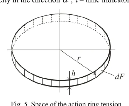
– Poisson’s ratio.It is possible to consider that the section surface in space consists of separate rings (fig. 5) which radius increases to a surface
sin
r C t
=
αα
, (4)where
α
– angle that determines the position of the point on the section,α
∈[
0; / 2π
]
;C
α– wave velocity in the directionα
;t
– time indicator.r
dF h
Fig. 5. Space of the action ring tension of identical value
The area of the ring will be determined by the formulation
( ) 2
dF
α
=
π
rh
, (5)where h – conventional thick rings,
h C td
=
αα
;or in a final form
2 2
( ) 2
sin
dF
α
=
π
C t
αα α
d
. (6)On the surface calculation section will apply tension and strain occurs as a reaction to external force. Different issues can be considered normal and tangential components of the stress acting on the ground tangent to the surface and cross section perpendicular to the direction of the force, etc. If in a general view to tell about full of tension
σ
α, forces directed to a point of application, that, con-sidering that the surface of section is formed by the sphere, the following dependence is offered2 2 0 2
cos
l
C
C
α
α
σ
=
σ
α
, (7)where
σ
0 – stress acting along the axis of applica-tion of forceP
.For the system which is in an equilibrium state (the static task is considered), the equation has to be carried out
2
0
cos
( )
P
dF
π
α
σ
α
α
=
∫
, (8)or, considering the previous formulas
2
2 2 2
0 0
2
lcos
sin
P
C t
d
π
π
σ
α
α α
=
∫
. (9)Equation (9) can be reduced to Boussinesq’s formulation definition of stress at a given depth
z
0 2
3
2
P
z
σ
π
=
. (10)The hypothesis is that at a movement speed
V
>
C
, the sphere (see Fig. 4) doesn’t manage to be created. In that case external loading will be counterbalanced by a smaller surface2 2 2
0 0
2 l cos sin
P C t d
β
π
σ
α
α α
=
∫
, (11)where
β
– angle, that determines the level of im-plementation areas,2 2 2
2 2
sin 1
1
l C V
ϕ
β
ϕ
⎛ ⎞
= ⎜ − ⎟
where
(
)
1 2
2 1
µ
ϕ
µ
−
=
−
.The level of increase in vertical tension, and re-spectively and deformations, it is possible to ex-press through coefficient which shows the reaction attitude from the full sphere (9) reactions from the limited sphere (11)
2
0
1
3
cos
sin
k
d
β
α
α α
=
∫
. (13)
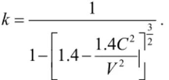
Given the above dependence and taking Pois-son’s ratio equal to 0.3, the rate of increasing in vertical stress and strain can be obtained in the form
3 2 2
2
1
1.4 1 1.4
k
C V =
⎡ ⎤
−⎢ − ⎥
⎣ ⎦
. (14)
More detailed calculations require taking into consideration that the bending deflection of rail consists not only of ground deformation that shape the wave front in the soil, being transferred from ballast different from the correct biaxial field [7], and so on. In a certain degree it is possible to reach applying the mode of modeling stated above [8]. As an example, in fig. 6 the dependence of a bend-ing deflection of rail a wheel from movement speed for the soil with the module of deformation of 10 MPa received by results of modeling taking into account the stated hypothesis is shown.
0 2 4 6 8 10 12 14
160 170 180 190 200 210 220 230 240 Running speed, km/hour
Ra
il
d
ef
le
ct
ion
, m
m
Fig. 6. The dependence of the rails deflection from the speed of the ground with
E
=10 MPaConsidered the characteristic of the soil there corresponds the cross speed of a wave 185 km/h. In fig. 6 significant growth in a rail deflection at the movement with speeds is observed, it is more than specified. Results are shown correspond to the experimental data given in work [15].
Findings
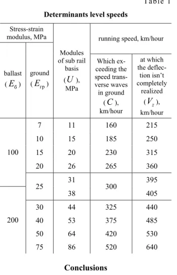
Using the wave model of stress-strain state lines was determined speed, which upon reaching deflection rail does not have time to acquire the «full» value. The calculations were performed according to the conditions described above (see. Fig. 3). The various options of basic data are considered. Selectively results of calculations are given in tab. 1. Thus the design of a track was pre-sented by ferroconcrete cross ties with distance of 0,54 m between shafts and a crushed-stone ballast 0,5 m thick under a cross tie.
According to the table it is possible to deter-mine movement speed (C), at which the observed increase in rail deflections, and speed (
V
z), in which will not have time to realize «full» deflec-tion rails. Speeds are specified on a major factor - the module of deformation of a soil. The module of elasticity of a sub rail basis was defined results of modeling of a deflection as the additional charac-teristic.Originality and practical value
The latest similar of the intense deformed con-dition of a railway track which allowed solving problems for which time for emergence of reac-tions in a railway track from a rolling stock plays an essential role are applied.
The offered theoretical justifications of proc-esses which take place at perception of loading elements of a railway track at high speeds of the movement.
Table 1
Determinants level speeds
Stress-strain
modulus, MPa running speed, km/hour
ballast (
E
б)ground (
E
гр)Modules of sub rail
basis (U),
MPa
Which ex-ceeding the speed trans-verse waves
in ground (C), km/hour
at which the deflec-tion isn’t completely
realized (
V
z), km/hour 7 11 160 215 10 15 185 250 15 20 230 315 20 26 265 360 10031 395 25
38 300 405 30 44 325 440 40 53 375 485 50 64 420 530 200
75 86 520 640
Conclusions
At the movement of the train on a railway track with a speed more cross speed of distribution of waves in a soil nature of perception of loading in sub rail to a basis changes that gives to notable (to two times) to increase in rails deflections.
In the presence of soft grounds, the rate limit of the movement, corresponding to emergence of the specified phenomenon, decreases. So, for soils with the module of deformation of 7 MPa, the cross speed of waves distribution makes only 160 km/h.
Even at such speeds time to ensure soil elastic deformation to form a trough rails. This is because the load is distributed on a ground layer of ballast that provides quick involvement ground interac-tion.
With further increasing the speed of the sub rail basis may not have time to implement the entire length of the deformation formation deflection rails. This would result in effect when the rail will not have time to fully bend. Even in soils with little
deformation modules (7…10 MPa) for the speed of the appearance of this effect has 215…250 km / h respectively. The level of speed, in addition to the characteristics of the soil (al-though they are crucial), also affect the properties of the layers of ground.
By drawing up a road bed of the ground which has the deformation module sufficient for provid-ing the general module of elasticity of a sub rail basis at the level of 40…50 MPa and more (that is put in the majority of track calculations on strength) are investigated effects can appear at rather big on today’s levels movement speed − 350…400 km/h and above.
LIST OF REFERENCE LINKS
1. Бондаренко, І. О. Вирішення задач надійності системи на основі моделювання напружено
-деформаційного стану залізничної колії засобами теорії розповсюдження пружних хвиль / І. О. Бондаренко, Д. М. Курган // Наука тапрогрестрансп. Вісн. Дніпропетр. нац. ун-ту залізн. трансп. – 2013. – № 1 (43). – С. 139–148. 2. Бондаренко, І. О. Застосування теорії розпов
-сюдження пружних хвиль для вирішення задач напружено-деформаційного стану залізничної колії / І. О. Бондаренко,
Д. М. Курган // Трансп. системиітехнології :
зб. наук. пр. ДЕТУТ. – Київ, 2011. – Вип. 18. –
С. 14–18.
3. Брандль, Х. Взаимодействие основанийисоо
-ружений высокоскоростных железных дорог
[Electronic resource] / Х. Брандль, А. Пауль
-мичл // XIII Дунайско-Европ. конф. по геотехнике (29.05-31.05.2006 г.). – Любляна,
Словения. – Режим доступу: http://www.ge-rec.spb.ru/journals/11/files/11009.pdf. – Назва
зекрана. – Перевірено : 17.02.2015.
4. Даніленко, Е. І. Залізнична колія. Улаштуван
-ня, проектування і розрахунки, взаємодія
з рухомим складом : підруч. для вищих навч.
закладів : в 2 т. / Е. І. Даніленко. – Київ :
Інпрес, 2010. – Т. 2. – 456 с.
5. Даніленко, Е. І. Правила розрахунків залізничної коліїна міцність і стійкість : ЦП -0117 / Е. І. Даніленко, В. В. Рибкін. – Київ :
Трансп. України, 2004. – 64 с.
6. Дослідження параметрів модернізованого земляного полотна / В. Д. Петренко,
А. М. Алхдур, О. Л. Тютькін, В. В. Ковалевич
// Вісн. Дніпропетр. нац. ун-ту залізн. трансп.
7. Кольский, Г. Волны напряжения в твердых телах / Г. Кольский. – Москва : Иностр. лит., 1955. – 192 с.
8. Курган, Д. Модель напряженно-деформиро
-ванного состояния железно-дорожного пути на основе волновой теории рас-пространения напряжений / Д. Курган, И. Бондаренко // Problemy Kolejnictwa. – 2013. – Vol. 159. – P. 99–111.
9. Транспортна стратегія України на період до
2020 року [Electronic resource] / Схвалено розпорядженням Каб. Міністрів України від 20 жовт. 2010 р. № 2174-р. – Режим доступу: http://zakon1.rada.gov.ua/laws/show/2174-2010-%D1%80. – Назва з екрана. – Перевірено : 17.02.15.
10. Фришман, М. А. Земляное полотно железных дорог / М. А. Фришман, И. Н. Хохлов,
В. П. Титов. – Москва : Транспорт, 1972. – 288 с. 11. Connolly, D. Numerical modelling of ground
borne vibrations from high speed rail lines on em-bankments / D. Connolly, A. Giannopoulos, M. Forde // Soil Dynamics and Earthquake Engi-neering. – 2013. – Vol. 46. – P. 13–19. doi: 10.1016/j.soildyn.2012.12.003.
12. Koch, E. A mélykeveréses technológia vasúté-pítési alkalmazásának lehetőségei / E. Koch, R. Szepesházi // SÍNEK VILÁGA. – 2013. – № 2. – P. 9–14.
13. Rail movement and ground waves caused by high-speed trains approaching track-soil critical veloci-ties / V. V. Krylov, A. R. Dawson, M. E. Heelis, A. C. Collop // Proc. of The Institution of Me-chanical Engineers Part F-journal of Rail and Rapid Transit. – 2000. – Vol. 214, № 2. – P. 107– 116. doi: 10.1243/0954409001531379.
14. Using three-dimensional finite element analysis in time domain to model railway–induced ground vi-brations / G. Kouroussis, L. Van Parys, C. Conti, O. Verlinden // Advances in Engineering Soft-ware. – 2014. – Vol. 70. – P. 63–76. doi: 10.1016/j.advengsoft.2014.01.005.
15. Woldringh, R. F. Embankment design for high speed trains on soft soils / R. F. Woldringh, B. M. New // Proc. of the 12th Europ. Conf. on Soil Me-chanics and Geotechnical Engineering (7.06-10.06.1999). – Amsterdam, The Netherlands, 1999. – Vol. 3. – P. 1703–1712.
Д
.
Н
.
КУРГАН
1*1*Каф. «Путьипутевоехозяйство», Днепропетровскийнациональныйуниверситетжелезнодорожноготранспорта имениакадемикаВ. Лазаряна, ул. Лазаряна, 2, Днепропетровск, Украина, 49010, тел./факс + 38 (056) 373 15 42,
эл. почта [email protected], ORCID 0000-0002-9448-5269
ОСОБЕННОСТИ
ВОСПРИЯТИЯ
НАГРУЗКИ
ЭЛЕМЕНТАМИ
ЖЕЛЕЗНОДОРОЖНОГО
ПУТИ
ПРИ
ВЫСОКИХ
СКОРОСТЯХ
ДВИЖЕНИЯ
Цель. Увеличение скоростей движения поездов требует не только соответствующих технических,
а и методико-расчетных решений. Большинство моделей и методик, которые используются для решения задач напряженно-деформированного состояния железнодорожного пути, базируются на допущениях
игипотезах, адекватныхтолькодляопределенныхскоростейдвижения. Врамкахданнойработыбудутрас
-смотрены теоретические предпосылки изменения характера восприятия нагрузки элементами железнодо
-рожногопутипривысокихскоростяхдвиженияиисследованычисловыепараметрыпроцессовприпомощи математического моделирования. В качестве практическойцели предполагаетсяпредоставить уровниско
-ростейдвиженияпоездов, вграницах которых можнообосновано исключитьвозможность появлениярас
-смотренных эффектов. Методика. Для решения поставленных задач была использована принципиально новаямодельжелезнодорожногопути, основаннаянаволновойтеориираспространениянапряженийвсис
-темеупругихтел. Дляисследованиявоздействияотподвижнойнагрузкиучитывалось, чтопрогибвопре
-деленномсечениипутиначинаетсяещевовремянахожденияколесананекоторомрасстоянии, апридвиже
-нииколесадальшеотвыбранногосеченияфронтволныупругойдеформациипродолжаетраспространяться.
-делены уровнискоростей движения поездов, в границах которых можно обоснованноисключать возмож
-ностьпоявления рассмотренныхэффектов. Научная новизна. Предложены теоретические обоснования и реализация в виде математической модели для процессов, которые возникают при восприятии нагрузки элементамижелезнодорожногопутипривысокихскоростяхдвижения. Практическаязначимость.Поре
-зультатаммоделирования полученыуровнискоростей движения, которыеопределяют появлениерассмот
-ренныхдинамическихэффектов вподрельсовомосновании. Онимогут бытьиспользованыдля обоснова
-нияконструкциипутиилиустановлениясоответствующихзначенийдопустимыхскоростей длявнедрения движениясвысокимискоростями.
Ключевыеслова:верхнеестроениепути; скоростноедвижение; напряжениевпути; прогибрельса; вол
-новаямодель; подрельсовоеоснование; деформациягрунта
Д
.
М
.
КУРГАН
1*1*Каф. «Коліятаколійнегосподарство», Дніпропетровськийнаціональнийуніверситетзалізничноготранспорту іменіакадемікаВ. Лазаряна, вул. Лазаряна, 2, Дніпропетровськ, Україна, 49010, тел./факс + 38 (056) 373 15 42,
ел. пошта [email protected], ORCID 0000-0002-9448-5269
ОСОБЛИВОСТІ
СПРИЙНЯТТЯ
НАВАНТАЖЕННЯ
ЕЛЕМЕНТАМИ
ЗАЛІЗНИЧНОЇ
КОЛІЇ
ПРИ
ВИСОКИХ
ШВИДКОСТЯХ
РУХУ
Мета. Збільшення швидкостей руху поїздів вимагає не тільки відповідних технічних, а й методично
-розрахунковихзасобів. Багатомоделей таметодик, щовикористовуютьсядлявирішеннязадачнапружено
-деформованогостанузалізничної колії, базуютьсянадопущенняхтагіпотезах, адекватнихтількидля пев
-нихрівнівшвидкостіруху. Врамкахданоїроботибудутьрозглянутітеоретичніпередумовизмінихарактеру сприйняттянавантаженняелементамизалізничноїколіїпривисокихшвидкостяхрухутадослідженічисель
-ніпараметрипроцесівзадопомогоюматематичногомоделювання. Вякостіпрактичноїметипередбачається надатирівнішвидкостейрухупоїздів, вмежахякихможнаобґрунтовановиключатиможливістьпоявирозг
-лянутихефектів. Методика.Длярішенняпоставленихзавдань булавикористанапринциповонова модель залізничноїколії, засновананахвильовійтеоріїрозповсюдженнянапруженьусистеміпружнихтіл. Длядо
-слідженнядіївідрухомогонавантаженнявраховувалось, щопрогинупевномуперерізіколіїпочинаєтьсяще підчас знаходження колеса надеякій відстані, апри зрушенні колеса далі від вибраного перерізу фронт хвилі пружної деформації продовжує поширюватись. За результатами моделювання досліджується зміна обрисуфронтухвилінапруженьучасідляпідрейковоїоснови. Якщошвидкістьрухупоїздасуттєвоменше за швидкість розповсюдження пружних хвиль, колесо залишається в зоні реалізованих деформацій.
Результати. Заваріантнимирозрахункамидлярізнихпараметрівзалізничноїколії (першзавсе, длярізних характеристик ґрунту) визначено рівні швидкостей руху поїздів, в межах яких можна обґрунтовано виключати можливість появи розглянутих ефектів. Наукова новизна. Запропоновано теоретичні обґрунтування та реалізацію у вигляді математичної моделі для процесів, що мають місце
під час сприйняття навантаження елементами залізничної колії при високих швидкостях руху.
Практична значимість. За результатами моделювання отримано рівні швидкостей руху, що визначають появу розглянутих динамічних ефектів у підрейковій основі. Вони можуть бути використані для обґрунтуванняконструкціїколіїабовстановленнявідповіднихзначеньдопустимихшвидкостейдлявпрова
-дженнярухузвисокимишвидкостями.
Ключові слова: верхня будоваколії; швидкісний рух; напруження в колії; прогин рейки; хвильова мо
-дель; підрейковаоснова; деформаціяґрунту
REFERENCES
1. Bondarenko I.O., Kurhan D.M. Vyrishennia zadach nadiinosti systemy na osnovi modeliuvannia napruzheno-deformatsiinoho stanu zaliznychnoi kolii zasobamy teorii rozpovsiudzhennia pruzhnykh khvyl [Solution of the problems of system reliability by modeling the stress-strain state of rail track using the theory of elastic waves propagation]. Nauka ta prohres transportu. Visnyk Dnipropetrovskoho natsionalnoho universytetu zaliznychnoho transportu – Science and Transport Progress. Bulletin of Dnipropetrovsk National University of Railway Transport,
2. Bondarenko I.O., Kurhan D.M. Zastosuvannia teorii rozpovsiudzhennia pruzhnykh khvyl dlia vyrishennia zadach napruzheno-deformatsiinoho stanu zaliznychnoi kolii [Application the theory of elastic waves distribution for the problems solution of stress-strain state of the railway]. Transportni systemy i tekhnolohii. Zbirnyk naukovykh prats Derzhavnoho ekonomiko-tekhnolohichnoho universytetu transportu [ Transport system and Technology. Proc. of State Economy and Technology University of Transport]. Kyiv, 2011, no. 18, pp. 14-18.
3. Brandl Kh., Paulmichl A. Vzaimodeystviye osnovaniy i sooruzheniy vysokoskorostnykh zheleznykh dorog. [The interaction of the grounds and structures of high-speed railways]. XIII Dunaysko-Yevropeyskaya konferentsiya po geotekhnike (29–31.05.2006). [Danube-European conference on geotechnical engineering, Lublin, Slovenia (29–31 May 2006)]. Lyublyana, Sloveniya. Available at: http://www.gerec.spb.ru/journals/11/files/11009.pdf (Accessed 17 February 2015).
4. Danilenko E.I. Zaliznychna koliia. Ulashtuvannia, proektuvannia i rozrakhunky, vzaiemodiia z rukhomym skladom
[Railway track. Device design and calculations, interaction with rolling stock]. Kyiv, Inpres Publ., 2010. Vol. 2. 456 p. 5. Danilenko E.I., Rybkin V.V. TsP-0117. Pravyla rozrakhunkiv zaliznychnoi kolii na mitsnist i stiikist [TsP-0117. The
computations rules of the railway track for strength and stability]. Kyiv, Transport Ukrainy Publ., 2004. 64 p. 6. Petrenko V.D., Alkhdur A.M., Tiutkin O.L., Kovalevych V.V. Doslidzhennia parametriv modernizovanoho
zemlianoho polotna [Research of parameters of the modernized subgrade]. Visnyk Dnipropetrovskoho natsional-noho universytetu zaliznychnatsional-noho transportu imeni akademika V. Lazariana [Bulletin of Dnipropetrovsk National University of Railway Transport named after Academician V. Lazaryan], 2012, issue 41, pp. 164-169.
7. Kolskiy G. Volny napryazheniya v tverdykh telakh [Stress Waves in Solids], Moscow, Inostrannaya literatura Publ., 1955. 192 p.
8. Кurgan D.М., Bondarenko I.О. Model napryazhenno-deformirovannogo sostoyaniya zheleznodorozhnogo puti na osnove volnovoy teorii rasprostraneniya napryazheniy [Model of the stress-strain state of the railway track on the basis of the straine-wave propagation theory]. Problemy Kolejnictwa, 2013, no. 159, pp. 99-111.
9. Transportna stratehiia Ukrainy na period do 2020 roku. № 2174-r [The transport strategy of Ukraine for the period till 2020 year. No. 21–74–r]. Available at: http://zakon1.rada.gov.ua/laws/show/2174-2010-%D1%80 (Accessed 17 February 2015).
10. Frishman M.A., Khokhlov I.N., Titov V.P. Zemlyanoye polotno zheleznykh dorog [Roadbed for railways]. Moscow, Transport Publ., 1972. 288 p.
11. Connolly D., Giannopoulos A., Forde M. Numerical modelling of ground borne vibrations from high speed rail lines on embank-ments. Soil Dynamics and Earthquake Engineering, 2013, vol. 46, pp. 13-19. doi: 10.1016/j.soildyn.2012.12.003.
12. Koch E., Szepesházi R. A mélykeveréses technológia vasútépítési alkalmazásának lehetőségei. Soil Dynamics and Earthquake Engineering, 2013, no. 2, pp. 9-14.
13. Krylov V.V., Dawson A.R., Heelis M.E., Collop A.C. Rail movement and ground waves caused by high-speed trains approaching track-soil critical velocities. Proc. of The Institution of Mechanical Engineers Part F-journal of Rail and Rapid Transit, 2000, vol. 214, no. 2, pp. 107-116. doi: 10.1243/0954409001531379.
14. Kouroussis G., Van Parys L., Conti C., Verlinden O. Using three-dimensional finite element analysis in time domain to model railway–induced ground vi-brations. Advances in Engineering Software, 2014, vol. 70, pp. 63–76. doi: 10.1016/j.advengsoft.2014.01.005.
15. Woldringh R.F., New B.M. Embankment design for high speed trains on soft soils. Proc. of the 12th Europ. Conf. on Soil Mechanics and Geotechnical Engineering (7.06-10.06.1999). Amsterdam, 1999, vol. 3, pp. 1703-1712.
Prof. V. D. Petrenko, D. Sc. (Tech.) (Ukraine); Prof. D. V. Laukhin, D. Sc. (Tech.) (Ukraine) recommended this article to be published