Complex Systems Informatics and Modeling Quarterly CSIMQ, Issue 10, March/April 2017, Pages 38–52
Published online by RTU Press, https://csimq-journals.rtu.lv https://doi.org/10.7250/csimq.2017-10.03
ISSN: 2255-9922 online
Combining Tools to Design and Develop Software Support for
Capabilities
Martin Henkel1*, Christina Stratigaki2, Janis Stirna1*, Pericles Loucopoulos2, Yannis Zorgios2 and Antonis Migiakis2
1
Stockholm University, Universitetsvägen 10, 114 18, Stockholm, Sweden 2
CLMS Ltd, KD207, 4-6 University Way, London, United Kingdom
[email protected], [email protected], [email protected] (orcid.org/0000-0002-3669-832X), [email protected] (orcid.org/0000-0003-1395-5001), [email protected], [email protected]
(orcid.org/0000-0001-6232-595X)
Abstract. Analyzing, designing and implementing software systems based on the concept of capabilities have several benefits, such as the ability to design efficient monitoring of capabilities and their execution context. Today, there exist new model-driven methods and development tools that support capability-based analysis, design, and implementation. However, there are also a plethora of existing efficient development tools that are currently in use by organizations. In this article, we examine how a new set of capability based tools, the Capability Driven Development (CDD) environment, can be combined with model-driven development tools to leverage both novel capability-based functionality and the proven functionality of existing tools. We base the examination on a case study where an existing model-driven tool is combined with the CDD environment.
Keywords: Capability modeling, capability design, model-driven development, Capability Driven Development.
1
Introduction
Organizational capabilities, representing the ability to handle resources such as people, goods, and services, can be supported by and contain traditional software systems. For example, large organizations may rely on standardized enterprise resource planning (ERP) systems. There are also emerging software systems and tools that work as add-ons to support the strategic run-time monitoring of capabilities and their execution context. Examples of these type of systems are business dashboard systems, presenting well-defined business metrics. However, these types of systems and their underlying development tools need to work together.
In this article, we present an approach that allows organisations to extend their existing traditional software systems and development tools with novel tools that particularly support the
*
Corresponding author
© 2017 Martin Henkel et al. This is an open access article licensed under the Creative Commons Attribution License (http://creativecommons.org/licenses/by/4.0).
39 design and run-time monitoring of capabilities and their contexts. The purpose of the approach is (a) to make it possible to compare the conceptual difference between existing tools and tools targeting design and run-time monitoring of capabilities, (b) to make it possible to, on a case-by-case basis, outline the benefits and effects of extending existing systems and tools with a new toolset, and (c) to make it possible to discern which method and software integrations need to be in place for such an extension.
To explain and elaborate the approach we describe how the combination of the following two toolsets could be achieved:
The Capability Driven Development (CDD) approach [1] contains methods and tools for the design and run-time monitoring of capabilities.
The zAppDev development environment is a model-driven development tool used for creating traditional software systems.
In order to combine the two toolsets, the tools need to be compared and integrated. We here outline four steps that can be followed to have a structured approach for selecting integration options, these are elaborated in detail in the following sections:
1. Analyze tool overlap.
2. Select design time integration options. 3. Select run-time integration options. 4. Summarize tool support needed.
The reason for the desire to combine CDD with existing tools such as zAppDev, is twofold. Firstly, a key component of CDD is the use of high-level graphical models, such as goal models, that are commonly missing from existing development tools. Secondly, existing tools provide a complete software development environment that may be used for creating complete software systems. The models used in CDD have a broader focus, describing organisational capabilities, their contexts, and goals. CDD does not include specific methods and tools for the detailed creation of information systems. However, it does provide tools that allow the analysis, design, and run-time monitoring of capabilities. This can be contrasted with traditional development tools that focus on components of software systems, such as data objects, information management procedures, user interface components, etc. Thus, combining the CDD approach with other development tools and systems gives the possibility of having support for capability analysis and monitoring (provided by CDD, or similar methods and tools) and the detailed implementation of information systems (provided by existing tools).
The examination presented in this article takes the form of a generic approach that allows an organisation to examine how CDD can be combined with existing tools. To illustrate the approach: how CDD is applied in an “industrial symbiosis platform” implemented by CLMS Limited is presented. The symbiosis platform is implemented using the state-of-art model-driven development (MDD) tool zAppDev. As each step of the approach is described in subsequent sections, we also describe how the MDD tool zAppDev may be combined with the CDD toolset. The work presented in this article is an extension of our examination of zAppDev presented in [2] and in this work we extend the examination with a deeper look at the conceptual tool differences.
40
2
Background
In this article, we use the concepts of capabilities and their context. These concepts have been described in the field of strategic management, enterprise modeling, and in research on
contextual systems. The tools that we are describing moreover are based on the concept of MDD. In strategic management the notion of dynamic capability [3] can be used to describe the ability of an organisation to evolve and thrive in changing environments. In management, dynamic capabilities are important because failure to change can endanger an organizations profitability or even its existence [4], [5]. The definition of the concept of capability itself has fluctuated somewhat in the area of strategic management; however, there is a tendency to associate it with the organisation of resources and their allocation [6]. In this article, we use this interpretation of capability, that is, we view resources and their use as an integral part of capabilities. We define a capability as the ability and capacity that enable an enterprise to achieve a business goal in a certain context [1].
In the area of enterprise modeling and enterprise architecture, the concept of capability has been used as a mean to analyse organisations [7], [8]. It has also been used to describe an organization’s ability to use enterprise architecture. This is most notable in the open groups TOGAF framework [9], where capability frequently refers the readiness of an organization to use enterprise architecture. Regarding strategic management and enterprise modeling, the contribution of this article is to show how the notions of capability and context can be realised, rather than adding to the existing methods and conceptual foundation of capability analysis and architecture.
Examining the research in contextual systems, it can be said that a focus has been on providing extensive and formal descriptions of the context, as well as on the development of context-aware systems. Generally, a context can be defined as information that can be used to characterize a situation of an entity [10]. We elaborate this definition in Section 3. The relationships of an entity (such as an organisation, or an organisational capability) to its environment are a part of the context. Ontologies have been proposed by several authors as a mean to formally describe contextual information. For example, in [11] and [12] the use of ontologies for context descriptions is central. There is also a class of systems referred to as context-aware systems that make context information an integral part of the IT systems. For example, [13] propose a system that in run-time replaces (software) services with adapted versions. Similarly, there have been proposals on how to design systems architectures for context aware systems, see for example [14] and [15]. What these context aware systems have in common is that they replace existing systems, or require substantial modification of existing systems. In contrast to this, the approach presented in this article provides a light-weight approach to extend existing systems with the ability to handle capabilities and their context.
41 used in parallel to exploit the advantages of each. The approach is not formalized and has no tool support in itself, but instead, focuses on providing stepwise guidance.
3
Introduction to the Industrial Symbiosis Case and CDD
This section provides an overview of how capability and context analysis was performed in the industrial symbiosis case. This follows the CDD approach, as defined in [1].
Industrial symbiosis is an association between two or more industrial actors in which the wastes or by-products of one become the raw materials for another. This collaboration between two or more companies is called a synergy. Traditionally, experts and consultants, involving highly complex, labor-intensive and error-prone tasks, manually performed the industrial symbiosis mediation process for matching between producers and consumers. However, the company CLMS has implemented an industrial symbiosis platform that is improving industrial symbiosis by automating the process of mixing and matching the interests of different actors in the waste resource chain, and by providing knowledge-based support for managing resources and finding compatible ones. The platform suggests compatible matches to a company and facilitates the creation of synergies for these matches.
For the purpose of improving the industrial symbiosis case, an identification of the capabilities within the business was done. Capability identification is the process of finding the capabilities that the business relies on to function. Identification can be done in several ways. For example, an identification based on recursive capability refinement is described in our earlier paper [7]. Moreover, the identification can be based on concept models, process models or goal models [23].
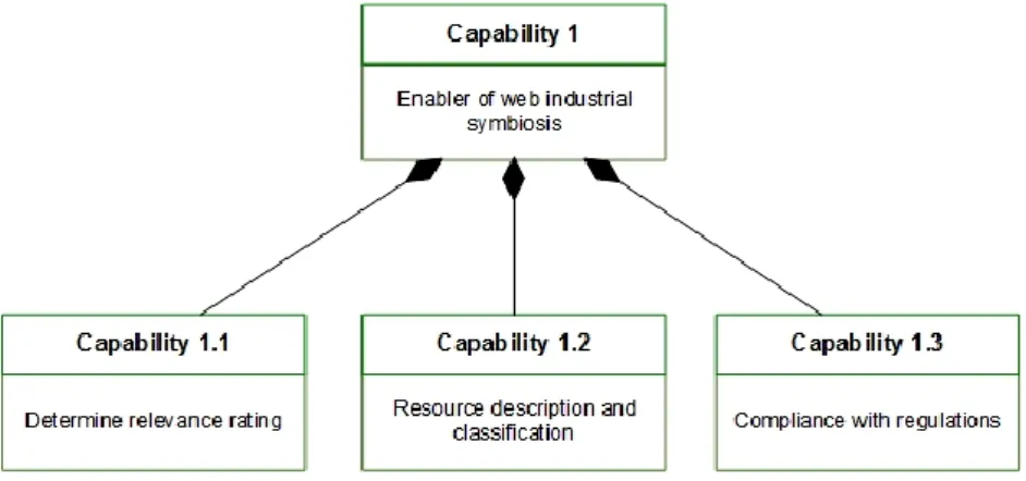
A small excerpt of the capability model is shown in Figure 1. Central to the business was, in this case, the capability to enable web industrial symbiosis (Capability 1 in Figure 1). This capability relies on it being true that a relevance rating can be determined for each symbiosis (Capability 1.1), that the resources can be described properly (Capability 1.2) and that the symbiosis is compliant with regulations (Capability 1.3). One example of the need for compliance with regulations is that the transport of hazardous goods is regulated. Capability 1 is dependent on the other capabilities, this is shown by using rhombs in Figure 1.
Figure 1. Excerpt from the capability model for the symbiosis case
42 organisation are legislation, weather, and even to some extent the behaviour of customers or external (IT) systems. Moreover, it is of interest to focus on external conditions that affect the capability as a whole, rather than a single instance of a capability. For example, the context in form of legislation may affect all ongoing work and future outcomes of a capability, while a change in how a single customer is sending their goods may only affect a limited part of ongoing work. Based on this discussion we make the definition in [10] specialized so that the context of a capability is the external information that affects the ability or capacity. This more specialized definition allows an analyst to focus on issues that may go undetected if only examining the regular flow of information that is used in a capability.
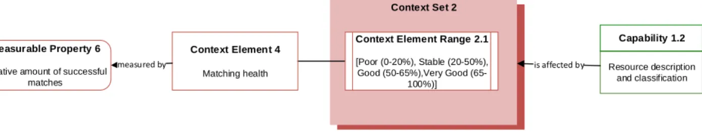
Figure 2 contains a small part of the context model for the capabilities in the symbiosis case. In the figure, we apply the CDD context model syntax to describe the context. A context element denotes the context, while a measurable property denotes a specific way to measure the context. Essentially, a context element can be based on one or several measurable properties. A context set is used to group potential ranges of context element values, these ranges are the expected values under which the capability can work. In Figure 2, it is shown that the resource description capability is affected by the context in the form of matching health (a context element), measured by the amount of relative matches in the system (a measurable property).
Figure 2. Excerpt from the CDD model depicting context information
The context model shown in Figure 2 can be extended by also introducing means to cope with changing contexts. For example, variation aspects could be described so that each can define how to handle certain context values.
The CDD approach is supported by a set of tools, covering both design time and run-time needs:
Capability Design Tool (CDT). This is the design time environment for creating capability and context models. For example, diagrams such as shown in Figure 2 can be drawn using the CDT.
Capability Navigation Application (CNA). This is a run-time tool used to monitor the context of a capability. Essentially, the current values of each context element are shown. The CNA can also signal whether the capability needs to be adjusted to accommodate changes in the context.
Capability Context Platform (CCP). This run-time tool works as a message broker that enables the monitoring of complex measurable properties from several context providers. The CCP continuously sends aggregated context information to the CNA.
The CDD approach also uses the concept of Capability Delivery Application (CDA) to denote the operational IT support system that a capability has. For example, the CDA can be in the form of an ERP system or a more specialized system that is a part of a capability. In our case, the symbiosis platform is the CDA.
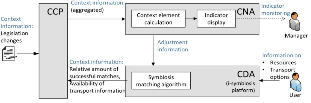
While CDT is used purely for design purposes, the CCP and CNA are used at run-time. Figure 3 shows a logical overview of how these tools are used in run-time for the industrial symbiosis case. For this symbiosis case, the context information is sent to the CCP from both external sources (legislation changes) and from the CDA (amount of successful matches and transport information). The CNA is used for calculating the context elements based on the measurable properties given by the CCP. The context element is displayed as indicators that can
Context Set 2
Resource description and classification
Capability 1.2
is affected by
Context Element Range 2.1
[Poor (0-20%), Stable (20-50%), Good (50-65%),Very Good
(65-100%)]
Context Element 4
Matching health
Measurable Property 6
Relative amount of successful matches
43 be viewed by a manager, moreover changes in the context element can trigger changes in the CDA's symbiosis matching algorithm.
Figure 3. overview of the symbiosis case use of the CDD tools
Note that even though these tools are defined in the context of CDD, the concepts of context provider (CCP), context display/navigation (CNA) and operational IT system (CDA) are generic. Thus, the approach is generic, even though it is described in terms of CDD.
4
Analyse Tool Overlap
If an organization uses a MDD tool (such as the zAppDev tool used in the symbiosis case) for design, it may be difficult to know which paths of the development should be combined, or used together with the CDD tools. Some concepts are unique for CDD tools, such as capability design. Other concepts, such as context elements and measurable properties, may have corresponding or overlapping concepts in the MDD tool. In an MDD tool such as zAppDev, the model concepts used are serving the need of developing more complete and domain oriented applications. It was noticed during the analysis of the symbiosis case that concepts on a high business level such as goals were not part of the model-driven architecture specification of zAppDev MDD tool.
Given the potential overlap of functionality between the CDD and the zAppDev an analysis of the conceptual differences between the tools was performed. The analysis was performed in three steps: (1) Identification of the concepts that the existing MDD tool uses, (2) Comparison of the existing MDD tools concepts with those of the CDD toolset, (3) Decision about the conceptual alignment of the tools. In practical terms, the three steps were performed first by a person that was experienced with the use of the CDD toolset and familiar with the zAppDev tool. A second validation was then done by a person experienced with CC, but also more experienced with the use of zAppDev.
In the following, we describe each of these steps and provide examples from the use of the zAppDev MDD tool in the symbiosis case.
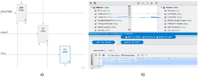
Identification of the existing MDD tool concepts. The purpose of this step is to understand all the concepts used in the MDD environment so that they can be compared with the tool support provided by the CDD toolset. Input for this step may be a specification of the existing MDD tool, or user manuals. Typically, it is also very helpful to have an example of how the tool is used in an existing application. The result is a list of concepts being used in the MDD tool. Table 1, column 1, shows a subset of the concepts being used in the zAppDev MDD tool. While the concept of using a domain model and data transformation (Table 1) is common in MDD tools, it is interesting to note that the zAppDev tool employs IDEF0 functional process diagrams (Figure 4) to describe the logic of a system.
Information on
• Resources
• Transport options Context information:
Relative amount of successful matches, Availability of transport information
CNA CCP
CDA (i-symbiosis platform) Symbiosis
matching algorithm Context element
calculation
Indicator display
Manager Indicator monitoring Context information:
(aggregated)
Adjustment information Context
information: Legislation changes
44
a) b)
Figure 4. Example of differences – a) zAppDev IDEF0 does not exist in CDD, b) zAppDev data transformations correspond to context element calculation in CDD
Table 1. Example of overlapping concepts’ table
zAppDev MDD tool concept
Corresponding CDD Concept
Correspondence
(semantics, abstract syntax, and concrete syntax) Functional model.
Drawn using the IDEF0 syntax. Contains functions, input, output, controls and mechanisms.
Process, Process variant
A zAppDev functional IDEF0 model consists of functions connected with data flow, while processes in CDD have activities connected with control flow. There is a semantic correspondence between functions and activities, and processes and functions. However, the interconnection of activities using control flow has only a syntactical correspondence to the use of data flows in zAppDevs functional model. The control flow used in CDD is simply not the same thing as data flow used in the zAppDev functional model.
Variation aspect A variation aspect in CDD is something that makes a capability to be executed differently. A similar concept in the zAppDev functional model is the IDEF0 control flows. A control flow enables or disables the execution of a function. However, a variation aspect can be seen as collection of variables, or information from the context, while a function control flow typically is a low-level variable. Thus, the correspondence is only on an abstract syntax level.
Domain model and
business objects.
Groups of concepts in the domain models forms business objects in zAppDev.
Context element, Measurable property
Context elements are used in CDD to represent contextual information that is affecting a capability. The domain model, and associated business objects, in zAppDev are used to design all information that the system should handle. Thus, a context element is a form of specialization of the contents of a business object. The correspondence is on an abstract syntax level.
Data
transformations.
Enable the mapping of two business objects.
Context element In CDD the context element represents an aggregation of one or several measurable properties. A measurable property can be considered as “raw” measurement, while a context element represents the transformation of the properties into a high-level interpretation. For example, the weather measurements 25 degrees and sunny may be translated into “good weather”. In zAppDev there is a general concept used for this kind of transformation called “data transformation”. Thus, there is a correspondence in functionality on the abstract syntax level.
45 The output from the step is a table with the concepts that overlap between the MDD and the CDD, and a description of the overlap.
Note that even if both tools contain a similar concept, such as goals, it may be used slightly differently in each tool. For example, goals in CDD are related to a capability on the business level, while a goal in MDD tools may be defined on a much lower (operational) level. To help clarify the differences between the concepts used in the tools we use a simple three-level comparison based on the UML [24] concepts of concrete syntax, abstract syntax, and semantics. If the concepts share only concrete syntax the concepts are named in a similar way, but have different meaning and are used differently. If the concepts share abstract syntax, the concepts have the same meaning, but may be used differently. For example, the concepts may be used on a different abstraction level. If the concepts have the same semantics, the concepts in CDD have the same use and meaning in the MDD tool.
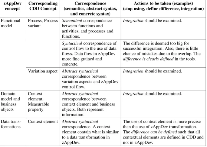
An excerpt of the result of comparing the zAppDev tool and CDD are shown in Table 2.
Table 2. Actions to be taken for overlapping concepts
zAppDev concept
Corresponding CDD Concept
Correspondence (semantics, abstract syntax,
and concrete syntax)
Actions to be taken (examples) (stop using, define difference, integration)
Functional model
Process, Process variant
Semantical correspondence between functions and activities, and processes and functions.
Integration should be examined.
Syntactical correspondence of control flow to the use of data flows. Data flow in zAppDev more fine grained and concrete.
The difference is deemed too big for successful integration. Also, there is little chance of mistakes due to the overlap. The
difference is clearly defined in the tools. Variation aspect Abstract syntactical
correspondence between variation aspects and zAppDev control flow.
Integration should be examined.
Domain model and business objects Context element, Measurable property Abstract syntactical correspondence between context element and business objects. Both represent information.
Integration should be examined.
Data trans-formations
Context element Abstract syntactical
correspondence. A context element contain what is similar to a data transformation in zAppDev.
The use of context element is more precise than the use of zAppDev transformation. The difference can be defined such that all contextual elements are defined in CDD and not in zAppDev.
Decision on how the two toolsets should be aligned. The objective of this step is to select the method of managing the overlap in functionality between the two tools. The input to the step is the list of conceptual overlap produced in the previous step. The output is a decision on how to handle each overlap. If there is no overlap, no action needs to be decided upon. However, if there is an overlap that is not handled it may lead to the duplication of functionality. To aid the decision on how to handle overlapping concepts we have created three options that provide guidance:
Stop using the concept in either MDD and/or CDD. This is to avoid confusion and possible errors. For example, if the MDD tool supports goal modeling, a decision may be made to stop using that functionality in favour of the CDD goal modeling.
46
- Example 1: Goal modeling in CDD may be used for high-level business goals, while in MDD the goals may be on a lower level, perhaps related to a single use case.
- Example 2: The information model in a MDD tool may have a detailed description of the information needed for each capability instance, while in CDD the context models may be on a more global level.
Integration. Make sure concepts from CDD can be synchronized with the MDD concepts. This option and its implications are discussed in the next section.
Table 2 summarizes the potential options for the symbiosis case and the zAppDev tool. Note that the table is an extension of the previous table.
Applying the above approach to analysing the difference between an existing tool and the CDD toolset leads to a better understanding of how the tools may be used together. In the next section we will explore the various options for tool integration.
5
Selecting Design Time Integration
The objective of this step is to decide how to integrate the design time tools of CDD and other tools that are currently in use. The design time tool of CDD is the CDT.
At design time, the components of the CDT environment and existing tools can be combined in several different ways. Depending on the overlap of the tools, and the desired design time functionality we have identified the following three options for performing design-time integration:
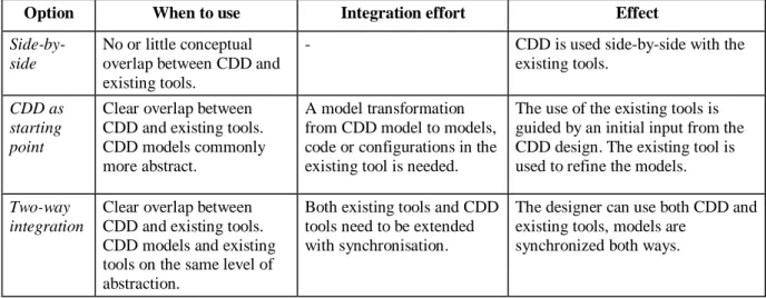
Side-by-side. Consider using the CDT as a side-by-side analysis tool that complements the existing tools. Essentially, this means that the CDT and the existing tools are used in parallel, and no integration is performed. On a general level, this option is useful if there is no overlap in the concepts used by the tools. This option is suitable when the CDD tools are just used for analysis purposes, and there is no need or desire to directly implement the CDD models in an IT system. The effect of choosing this option is that CDD is used as a side-by-side tool without any integration with the existing tools.
CDT as a starting point for using the existing tools. Using this option means that the models in CDT are used as input to create the initial solutions in the existing tools. A CDT model can be transformed into a model in an existing MDD tool, or be used to generate code or configurations that can be further edited in existing tools. For example, the context models (Figure 2) could be the base for creating an information model in a MDD tool, or an initial database schema in a DBMS. This option is useful if there is some form of overlap of the models, since some conceptual resemblance is needed to generate code or models from CDT. The effect of using this option is that initial models, code or configurations will be generated. However, the connection between CDD tools and the existing tools is one-way.
Two-way integration between CDD and existing tools. This is similar to the option of using the CDD as a starting point. However, here there is also a two-way integration, meaning that when changes are performed in the existing tool they should automatically be propagated to the CDD as well. The effect of using this option is that designers can work in an iterative fashion, performing updates in both the CDD and existing tools.
47
Table 3. Design time integration options
Option When to use Integration effort Effect
Side-by-side
No or little conceptual overlap between CDD and existing tools.
- CDD is used side-by-side with the
existing tools.
CDD as starting point
Clear overlap between CDD and existing tools. CDD models commonly more abstract.
A model transformation from CDD model to models, code or configurations in the existing tool is needed.
The use of the existing tools is guided by an initial input from the CDD design. The existing tool is used to refine the models.
Two-way integration
Clear overlap between CDD and existing tools. CDD models and existing tools on the same level of abstraction.
Both existing tools and CDD tools need to be extended with synchronisation.
The designer can use both CDD and existing tools, models are
synchronized both ways.
The design time integration options rely on the fact that the conceptual overlap has been successfully identified in the previous step (“Analyze tool overlap”). For example, if the models are on different abstraction levels this difference would have been identified during the analysis. A concrete example of this is where one tool uses platform independent models (PIM) and the other tool uses platform specific models (PSM), this would be identified as a difference in the abstract syntax. In this concrete example, the CDD as a starting point or two-way integration may be chosen (see Table 3). The approach presented here currently does not provide any further guidance on how the tools should be integrated technically. The integration effort (Table 3) may very well be affected by the tools technical implementation, for example, the absence of application programming interfaces (APIs) may make integration difficult or impossible.
5.1 Design Time Options in the Symbiosis Case
In the symbiosis case CLMS use the advanced zAppDev MDD tool to develop the symbiosis platform. We here describe two cases of how the CDT and zAppDev tools can be integrated at design time using the CDD as the starting point for the existing tools option.
CDD context model to zAppDev domain model. Comparing CDD and zAppDev a conceptual
overlap can be found the CDD context models and zAppDevs domain models. A domain model in zAppDev depicts the information that the system is processing. By model transformations built into zAppDev the domain models become a relational database schema. The context models in CDD contain the concepts used for describing the context of a capability. If desired, the context model could be used as the basis for generating a domain model. By importing the CDD model into zAppDev, a solution engineer could get a draft of the context concepts needed in the domain model.
48
6
Selecting Run-Time Integration
The purpose of this step is to decide how to integrate the run-time tools of CDD and the IT system currently supporting the capability under study.
At run-time the CDD tools, namely, CNA and CCP, can provide a valuable addition to an existing IT system, or a system that is being designed. Using the CDD nomenclature such a system is denoted CDA – Capability Delivery Application. The CDA can be implemented using a model-driven tool, or using a traditional development environment. While CDD can be used as a design-time aid, there are additional benefits using it in run-time to extend the existing systems. We here distinguish between two options of run-time use; as a monitoring tool and as an
adjustment tool. The two options and sub-options are discussed below.
6.1 Monitoring Tool Extension
Using the CPP and CNA as monitoring tools entails making use of the CNA to monitor the context of capabilities. That is, the existing system can be extended by allowing the users to monitor the context using the CNA. For this purpose two variants can be selected:
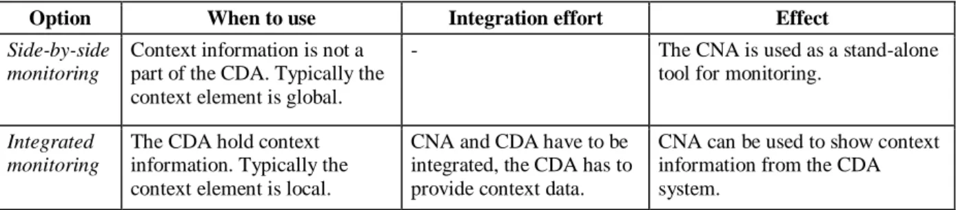
a) Side-by-side monitoring. In this option, the CDD is treated as an add-on to existing systems, and no run-time integration is performed. CDD is simply used to monitor how the context changes. For this option to be useful, the context must be defined so that it is not a part of the CDA. Otherwise, an integration is needed to extract the context information from the CDA. Typically, side-by-side monitoring can be used for context elements that are affecting several instances of a capability, while context elements that are bound to a single instance are commonly an integral part of a CDA.
b) Integrated monitoring. This option can be used when the context information is held within the CDA. Typically the context information is local, that is it describes the context of a single capability instance as it is executing. For this option, there is a need to implement a
data provider in the CDA that sends information to the CCP. Since the CNA is designed for handling global context, there is also a need to perform data aggregation.
Table 4 provides an overview of the monitoring options, and the effect and integration effort they come with.
Table 4. Summary of run-time monitoring options
Option When to use Integration effort Effect
Side-by-side monitoring
Context information is not a part of the CDA. Typically the context element is global.
- The CNA is used as a stand-alone
tool for monitoring.
Integrated monitoring
The CDA hold context information. Typically the context element is local.
CNA and CDA have to be integrated, the CDA has to provide context data.
CNA can be used to show context information from the CDA system.
Note that a special case of when side-by-side monitoring should be selected is if the existing CDA does not support run-time monitoring at all.
6.2 Adjustment Tool Extension
49 cases. For example, some adjustments may need to be manually designed and applied when the context changes. An example of this kind of adjustment is when changes need to comply with new regulations – changed regulations may have a complex impact on the system, which may be impossible to foresee. For each context element, there is thus a need to discern whether a fully automatic adjustment can be made, or if a manual adjustment is a better option. To guide the adjustment selection, we below describe three options ranging from fully automatic to manual.
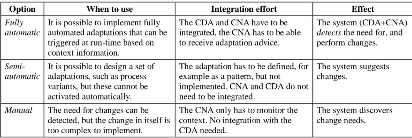
a. Fully automatic. This option allows the run-time discovery of context changes, and the triggering of adjustment running capabilities to cope with these changes. This requires that (1) the CNA has access to the context element, (2) that the CDA is able to receive information about needed changes, and (3) that the CNA is able to notify the CDA when changes should occur. The effect of implementing this option is that the system can perform changes.
b. Semi-automatic. In this option, the system can detect changes in the context and suggest adaptations that are manually implemented. For example, this is a useful option if the changes needed are in the form of manual routines. This option requires that (1) the CNA has access to context elements, and (2) that manual adaptations are defined. One option for defining manual adaptations is in the form of patterns. For example, in a help-desk, there may be two different manual routines for answering questions under a high load compared with a low load situation (in this example the current load is considered a part of the context). The effect of using this option is that the system can suggest changes.
c. Manual. For some context changes it may be difficult to adapt automatically, or even suggest how to address them. An example of this mentioned earlier is the adaptation to new legislation. However, in this case, the context can be monitored with the help of CDD tools, and when a change occurs it can be handled manually. For example, a change in legislation may be monitored in order to start a manual analysis of the impact of the change when it occurs. This option requires no run-time integration with the CDA. The effect of using this option is that the system can discover changes.
Table 5 gives an overview of the effects, integration effort and recommendation of when to use each of the run-time adaptations options.
Table 5. Summary of run-time adaptation options
Option When to use Integration effort Effect
Fully automatic
It is possible to implement fully automated adaptations that can be triggered at run-time based on context information.
The CDA and CNA have to be integrated, the CNA has to be able to receive adaptation advice.
The system (CDA+CNA)
detects the need for, and perform changes.
Semi-automatic
It is possible to design a set of adaptations, such as process variants, but these cannot be activated automatically.
The adaptation has to be defined, for example as a pattern, but not implemented. CNA and CDA do not need to be integrated.
The system suggests changes.
Manual The need for changes can be detected, but the change in itself is too complex to implement.
The CNA only has to monitor the context. No integration with the CDA needed.
The system discovers change needs.
6.3 Run-Time Options in the Symbiosis Case
50 of the measurable property to the CCP, which in turn sends it to the CNA. This is done by implementing a CCP data provider. The CNA is then used to monitor the context element (this means that the CNA will display values from the context element range such as “Poor”, “Stable”, etc., see Figure 2).
7
Summarize Tool Support Needed
In this step an overview of the integration need is created, to enable the planning of the integration implementation. Essentially, the options selected in steps 2 and 3 can be summarized in one large list. This list will include the types of integration options that are needed for a case. If there is a need to perform one single type of integration several times this may be the impetus to implement a generic and reusable solution. For example, there might be several context elements that have been selected for the option integration monitoring at runtime. In this case, it is beneficial to implement a generic integration that allows the existing development tool to create the needed integrations for all these elements. On the other hand, if only one context element needs integration monitoring at runtime it may be more cost-effective to perform the integration without having to change the existing development tool or implement generic integrations.
For a tool vendor, the run-time and design time options selected will have an impact on the type of integration that the tool has to support.
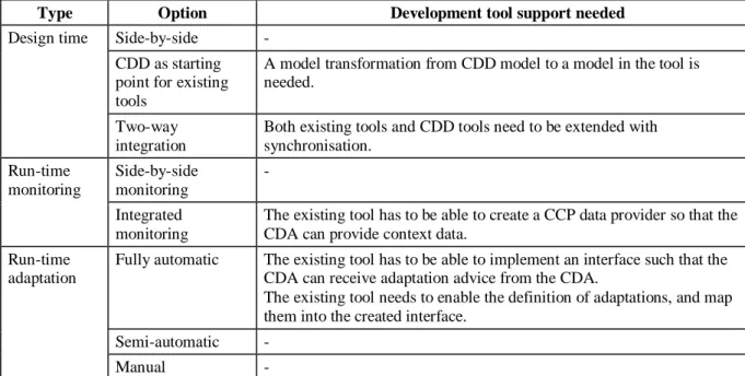
Table 6 summarizes the integration needs per option. Note that some options do not affect the existing tool at all. For a tool to have the full support of CDD most, if not all, of the integration options should be supported.
Table 6. Summary of integration needs
Type Option Development tool support needed
Design time Side-by-side -CDD as starting point for existing tools
A model transformation from CDD model to a model in the tool is needed.
Two-way integration
Both existing tools and CDD tools need to be extended with synchronisation.
Run-time monitoring
Side-by-side monitoring
- Integrated
monitoring
The existing tool has to be able to create a CCP data provider so that the CDA can provide context data.
Run-time adaptation
Fully automatic The existing tool has to be able to implement an interface such that the CDA can receive adaptation advice from the CDA.
The existing tool needs to enable the definition of adaptations, and map them into the created interface.
Semi-automatic -
Manual -
8
Conclusions
51 the second step, design-time options are selected such that a potential system analyst and/or developer can work with both CDD and existing MDD tools. The third step includes selecting run-time options, enabling the potential interconnection of the executable result of the CDD and the MDD tools. The last step involves an overview of the potential changes that need to be made to existing development tools.
The four-step approach has been described using the nomenclature of CDD, an approach for capability analysis and design. However, the approach is sufficiently generic to be applied to other methods and tools as well.
Acknowledgments. This work has been partially funded by the EU-FP7 funded project
no. 611351 CaaS – Capability as a Service in Digital Enterprises.
References
[1] S. Bērziša, G. Bravos, T. Cardona Gonzalez, U. Czubayko, S. España, J. Grabis, M. Henkel, L. Jokste, J. Kampars, H. Koç, J.-C. Kuhr, C. Llorca, P. Loucopoulos, et al. “Capability Driven Development: An Approach to Designing Digital Enterprises,” Business & Information Systems Engineering, vol. 57, no. 1, pp. 15–25, 2015. Available: https://doi.org/10.1007/s12599-014-0362-0
[2] M. Henkel, C. Stratigaki, J. Stirna, P. Loucopoulos, Y. Zorgios and A. Migiakis, “Extending Capabilities With Context Awareness,” in International Conference on Advanced Information Systems Engineering Workshops, Springer, vol. 249, pp. 40–51, 2016. Available: https://doi.org/10.1007/978-3-319-39564-7_4
[3] D.J. Teece, “Explicating Dynamic Capabilities: The Nature and Microfoundations of (Sustainable) Enterprise Performance,” Strategic Management Journal, vol. 28, no. 13, pp. 1319–1350, 2007. Available: https://doi.org/10.1002/smj.640
[4] P.G. Audia, E.A. Locke and K.G. Smith, “The Paradox of Success: An Archival and a Laboratory Study of Strategic Persistence Following Radical Environmental Change,” Academy of Management Journal, vol. 43, no. 5, pp. 837–853, 2000. Available: https://doi.org/10.2307/1556413
[5] R.R. Wiggins and T.W. Ruefli, “Schumpeter's Ghost: Is Hypercompetition Making the Best of Times Shorter?,” Strategic Management Journal, Wiley, vol. 26, no. 10, pp. 887–911, 2005. Available: https://doi.org/10.1002/smj.492
[6] G. Schreyögg and M. Kliesch‐Eberl, “How Dynamic Can Organizational Capabilities Be? Towards a Dual-Process Model of Capability Dynamization,” Strategic Management Journal, Wiley, vol. 28, no. 9, pp. 913– 933, 2007. Available: https://doi.org/10.1002/smj.613
[7] M. Henkel, I. Bider and E. Perjons, “Capability-Based Business Model Transformation,” in Advanced Information Systems Engineering Workshops (CAISE’14), Springer International Publishing, pp. 88–99, 2014. Available: https://doi.org/10.1007/978-3-319-07869-4_8
[8] J. Stirna, J. Grabis, M. Henkel and J. Zdravkovic, “Capability Driven Development – an Approach to Support Evolving Organizations,” in The Practice of Enterprise Modeling, Springer Berlin Heidelberg, pp. 117–131, 2012. Available: https://doi.org/10.1007/978-3-642-34549-4_9
[9] Open Group Standard, “TOGAF – Enterprise Architecture Methodology,” Version 9.1., 2011. Available: http://www.opengroup.org/togaf/ (accessed 17.02.2017)
[10]A. Dey, “Understanding and Using Context,” Journal of Personal and Ubiquitous Computing, Springer, vol. 5, no. 1, pp. 4–7, 2001. Available: https://doi.org/10.1007/s007790170019
[11]R. Hervás, J. Bravo and J.A. Fontecha, “Context Model Based on Ontological Languages: a Proposal for Information Visualization,” Journal of Universal Computer Science, vol 16., no. 12, pp. 1539–1555, June 28, 2010. Available: https://doi.org/10.3217/jucs-016-12-1539
[12]P. Moore, B. Hu and J. Wan, “Smart-Context: a Context Ontology for Pervasive Mobile Computing,” The Computer Journal, Oxford University Press on behalf of The British Computer Society, vol. 53, no. 2, pp. 191– 207, Feb. 1, 2010. Available: https://doi.org/10.1093/comjnl/bxm104
52 [14]M. Baldauf, S. Dustdar and F. Rosenberg, “A Survey on Context-Aware Systems,” International Journal of Ad Hoc and Ubiquitous Computing, Inderscience Publishers, Geneva, SWITZERLAND vol. 2, no. 4, pp. 263– 277, Jan. 1, 2007. Available: https://doi.org/10.1504/IJAHUC.2007.014070
[15]S. Vale and S. Hammoudi, “COMODE: A Framework for the Development of Context-Aware Applications in the Context of MDE”, in Proc. the 4th International Conference on Internet and Web Applications and Services (ICIW’09), IEEE, pp. 261–266, 2009. Available: https://doi.org/10.1109/ICIW.2009.44
[16]M. Völter, T. Stahl, J. Bettin, A. Haase and S. Helsen, “Model-Driven Software Development: Technology, Engineering, Management,” Wiley Software Patterns Series, Wiley, Chichester, pp. 448, 2013. Available: https://books.google.de/books?id=9ww_D9fAKncC&hl=de
[17]D.C. Schmidt, “Model-Driven Engineering,” IEEE Computer Society, IEEE, vol. 39, no. 2, pp. 25–31, 2006. Available: https://doi.org/10.1109/MC.2006.58
[18]R. France and B. Rumpe, “Model-Driven Development of Complex Software: A Research Roadmap,” Future of Software Engineering, IEEE Computer Society, pp. 37–54, 2007. Available: https://doi.org/10.1109/fose.2007.14
[19]M. Henkel and J. Stirna, “Pondering on the Key Functionality of Model Driven Development Tools: The Case of Mendix,” in Perspectives in Business Informatics Research, Springer Berlin Heidelberg, pp. 146–160, 2010. Available: https://doi.org/10.1007/978-3-642-16101-8_12
[20]J. Whittle, J. Hutchinson and M. Rouncefield, “The State of Practice in Model-Driven Engineering,” IEEE Software, IEEE, vol. 31, no. 3, pp. 79–85. Available: https://doi.org/10.1109/MS.2013.65
[21]B. Hoisl, M. Strembeck and S. Sobernig, “Towards a Systematic Integration of MOF/UML-Based Domain-Specific Modeling Languages,” in Proc. the 16th IASTED International Conference on Software Engineering and Applications, ACTA Press, pp. 337–344, 2012. Available: https://doi.org/10.2316/p.2012.790-045 [22]G. Giachetti, B. Marín and O. Pastor, “Integration of Domain-Specific Modelling Languages and UML
Through UML Profile Extension Mechanism,” International Journal of Computer Science and Applications, Technomathematics Research Foundation, vol 6, no. 5, pp. 145–174, 2009. Available: http://www.tmrfindia.org/ijcsa/v6i56.pdf
[23]K. Sandkuhl, H. Koç and J. Stirna, “Context-Aware Business Services: Technological Support for Business and IT-alignment,” in Business Information Systems Workshops, Springer International Publishing, pp. 190– 201, May 22, 2014. Available: https://doi.org/10.1007/978-3-319-11460-6_17