A Universal Device Controller (UDC)
Praveen Palanisamy
School of Electrical EngineeringVIT Chennai, India
ABSTRACT
This paper proposes a universal device controller which enables people to control day to day devices and appliances around them with a vastly reduced complexity and effort. This paper details the implementation of a unified hardware platform for monitoring, controlling and automating everyday electronic appliances and devices. The proposed solution is flexible and capable of expansion. The universality of the proposed device enables people to use their own smartphones, tablets or PCs as the remote to control appliances, devices or robots not only at their home or workplace but anywhere they go.
General Terms
Universal control, consumer device, home automation, smart monitoring, smart communication.
Keywords
Universal Device Controller (UDC)
1.
INTRODUCTION
There is still a need for a cheap, low-power, all-purpose and flexible everyday automation/control device in the market which would manage and monitor all the day to day electronic appliances and activities. However, scenarios in which devices communicate with each other and provide remote monitoring and control features to the people have yet to reach the mainstream. Although many automation solutions for homes, offices and common places exist, they are not universal. The solutions proposed in [1], [2], [3], [4] and [5] are very specific and the systems have limited functionalities. With the advent of smart mobile devices it has become easier than ever to conveniently manage and automate different aspects of our day-to-day life. With more and more smart appliances coming to the market at an affordable price, their penetration into common households and other common places is evident. This brings up a need for a universal solution to monitor and control these devices and appliances in a simpler way to the present and future mobile device world.
The rest of this paper is structured as follows. Section II describes the solution provided by the proposed device and its merits over existing solutions. Section III describes the system in detail. Hardware description and implementation of the proposed device is detailed in section IV. The tests conducted and the results obtained are presented in section V.
2.
PROPOSED SOLUTION
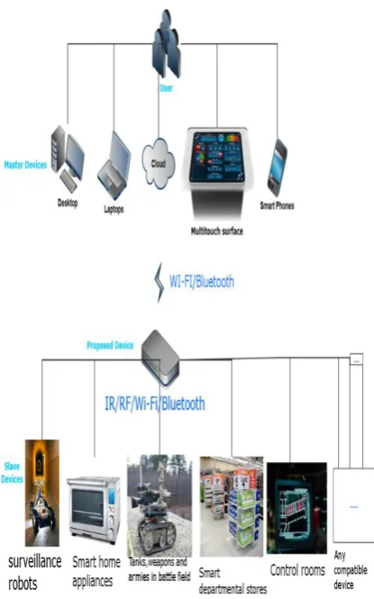
The proposed Universal Device Controller (UDC) provides a universal solution for real-time monitoring and control of day to day appliances and devices. The devices that can be controlled includes electrical appliances like Air conditioners, televisions, fridges, washing machines, toaster, electric
Fig 1: Use case scenarios of the proposed device.
3.
DESCRIPTION OF THE SYSTEM
3.1
Components of the system
Fig. 2 Simple block diagram of the system.
3.1.1
Master Device
Master device can be any device that the user possesses with either Wi-Fi or Bluetooth connectivity. Users use it to control the slave device(s) with the help of the UDC. UDC helps it in two ways: (1) generates an intuitive and easy-to-use interface which the master device can present to the user and (2) enhances the capability of the master device by enabling it to control devices which was not possible due to hardware limitations.
3.1.2
Slave Device
Slave device is any device or appliance which provides a way of external control. It is preferably a device which exposes the interface to which it responds to control requests or transmits status information. Any node in a wireless sensor network is compatible.
3.1.3
Universal Device Controller
UDC is the proposed device which acts as an intermediary between the master and the slave devices. It provides an easy-to-use control interface to the users irrespective of the hardware and software platform of the master device they use.
3.2
Interaction between master device(s)
and UDC
Interaction between the master device(s) and UDC is independent of the type and functionality of the slave device(s) the user wishes to control. It can be done in the following ways:
3.2.1
Via Bluetooth
The UDC keeps itself visible to all Bluetooth enabled devices. The user can pair their master device(s) with the UDC. Once paired, the UDC sends out a HTML form using the OBEX Object Push Profile (OPP) with a list of controllable slave devices available in that area and an optional field to enter a token. The token determines the privileges of the user. By default all the users are treated as guests. On submission of the form, the form data is sent to the UDC using the Serial Port Profile (SPP).On validation of the form data, UDC sends out a Graphical Control User Interface (GCUI) using the OBEX OPP. The interface contains pushbuttons and/or dial knobs and/or sliders depending upon the type and number of control options available for the slave device(s) selected by the current user.
3.2.2
Via Wi-Fi
UDC creates and keeps an ad-hoc network active. Once the user connects to the UDC with their master device(s) a shared folder is made available for the user which is accessible form the master device(s). The folder contains HTML files for each controllable slave device available in that area. The HTML file can be parsed by any web browser irrespective of the hardware or software platform. It provides the GCUI for the user. The commands from the user are then communicated to the slave device(s) by the UDC.
3.3
Interaction between UDC and slave
device(s)
Interaction between UDC and the slave device(s) are independent of the protocol or medium of communication between the master device(s) and UDC. UDC manages the translation of commands and sends control signals through one of the following medium:
3.3.1
Via Infra-Red
UDC has the advantages of both pre-programmed remotes and learning remotes. UDC can control more than 2,000 devices across 227 brands which respond to Pulse width modulated IR signals. UDC makes use of pronto hex codes [9] to accomplish this. The pronto hex format uses a pair of numbers to represent on/off sequence. The UDC also has an IR learning mechanism which enables it to control IR devices apart from those 2,000 plus devices. (Refer to Implementation section for details).
3.3.2
Via RF
Zigbee is the widely used standard in wireless control and monitoring applications. Most of the existing home automation solutions and wireless sensor network nodes use zigbee for the wireless link because of its cost and low-power consumption. The ZigBee RF4CE [10] specification offers an immediate, low-cost, easy-to-implement solution for control of products. It operates in the 2.4GHz frequency band according to IEEE 802.15.4. ZigBee's standardized pairing process allows for fast and easy association between devices. The UDC acts as the coordinator node. It obtains the PAN ID and MAC address of the slave device(s) through the discovery process. It then sends an NLME-PAIR.Request to the target. The NLME-PAIR.Request contains the following fields:
Master
• Destination Channel (The two devices will use this channel for their communication.)
• Destination PAN ID
• Destination IEEE address • Source application capability
• Source Device ID list • Source Profile List
• Key exchange transfer count (Defines the number of transfers made by the target before changing the link key)
3.3.3
Via Wi-Fi
UDC sends supported commands to the slave device(s) through the ad-hoc network established between the two. Internally, UDC sends the commands serially through UART and integrates the functions of IEEE 802.11 protocol using a Wi-Fi-UART bridge
3.3.4
Via Bluetooth
UDC uses Simple Secure Pairing (SSP) to pair with the Bluetooth enabled slave device(s). It then uses the Serial Port Protocol (SPP) to interact with the slave device(s).
4.
IMPLEMENTATION
[image:3.595.323.537.77.289.2]The hardware block diagram of UDC is shown in Fig. 6. It uses Stellaris LM3S1958, a 32-bit ARM Cortex-M3 based microcontroller operating up to 50MHz, with 256 kB flash and 64 kB SRAM. Roving networks’ RN-171-XV 802.11 b/g Wireless LAN Module was used for Wi-Fi connectivity with a TTL UART interface. SPA310, serial port adapter –Bluetooth module was used to provide the SPP and OPP required by UDC. Digi’s series 2 XBEE module was used to configure UDC as a coordinator in a zigbee network. For IR, TSOP98200 [11], a wide band IR sensor for code learning was used. The sensor covers the entire remote control bandwidth of 30 KHz to 455 KHz. It is capacitively coupled to prevent activation of the sensor from constant light sources such as tungsten bulbs or sunlight. This provides optimal reception of the IR code while learning even in the presence of these light sources.
Fig. 3 TSOP receiver and IR LED sender circuits.
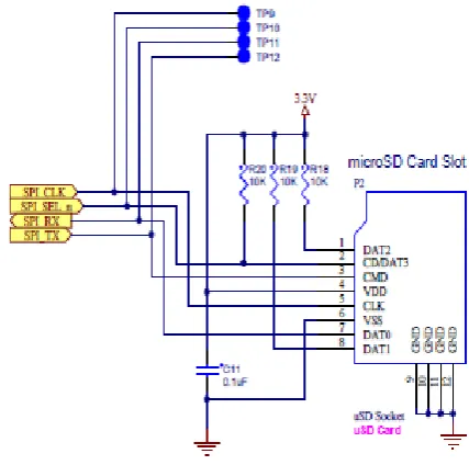
[image:3.595.317.542.349.481.2]A micro SD card slot was added for storing the pronto hex codes for the 2,000 plus devices and also for logging purposes.
Fig. 4 Micro SD Card slot connections.
A 3.5” TFT panel with an integrated controller (SSD2119 [12]) and a small magnetic audio transducer (speaker) was added to provide feedback.
Fig. 5 (Optionally) A display used for providing feedback to the user.
Four ADC channels and four GPIO lines connect directly to the resistive touch panel, allowing the microcontroller to manage all aspects of input operation.
[image:3.595.62.277.513.688.2] [image:3.595.317.541.549.744.2]5.
TESTS AND RESULTS
5.1
Test Setup 1
[image:4.595.68.268.159.288.2]Setup 1 consists of four different types of slave devices available in a region where the UDC is present. Fig. 7 (left) shows a Bluetooth controlled wheeled robot (slave device) is shown with a smart phone used as the master device. Fig. 7 (right) shows a plug-point with Wi-Fi connectivity.
[image:4.595.62.272.165.416.2]Fig. 7 Bluetooth controlled robot (left). A Wi-Fi connected plug point (right).
Fig. 8. A zigbee LED node (left). Zigbee temperature sensor node (right).
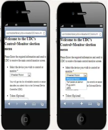
Fig. 8 (left) shows Zigbee enabled LED bulbs and Fig. 8 (right) shows the zigbee enabled temperature sensor. Once the user connected to UDC, it sent out a device selection menu as shown in Fig. 9. The sample GCUI sent by the proposed device to the master device for the user selected slave device is shown in Fig. 9 (left most).
Fig. 9 Menu sent by UDC to the master device.
This test setup shows the ability of the proposed device to enable controlling and monitoring of different kinds of slave devices as proposed. The user is able to control devices which operate on different control interfaces with a single device which they already own.
5.2
Test Setup 2
[image:4.595.318.541.184.354.2]Test setup 2 comprises of a Wi-Fi enabled tablet and a TV which accepts input from an IR remote. The setup is explained in Fig. 10.
Fig. 10 Test setup 2
This test setup shows how the proposed device smartly translates the user’s commands into Pulse width modulated IR signals. This eliminates the inconvenient way of point and click control of IR based devices.
5.3
Test Setup 3
This setup comprises of a zigbee enabled wheeled robot as the slave device and a zigbee enabled PC as the master device. This test setup shows the capability of the proposed device to coordinate zigbee nodes in any wireless sensor network.
Fig. 11 Test setup 3.
[image:4.595.317.544.468.642.2] [image:4.595.81.257.537.749.2]6.
CONCLUSION
The components and implementation details of a unified hardware platform for monitoring, controlling and automating everyday electronic appliances and devices were presented. The proposed universal device controller is expandable to incorporate future communication technologies and is flexible to be modified to work with devices running on various hardware and software platforms.
7.
REFERENCES
[1] Wanjoo Park , Hyunchul Cho , Sehyung Park Laehyun Kim, "An universal remote controller with haptic interface for home devices," in Digest of Technical Papers International Conference on Consumer Electronics, Las Vegas, NV, 2010, pp. 209 - 210.
[2] P Czamul, "Design of a distributed system using mobile devices and workflow management for measurement and control of a smart home and health," in 6th International conference on Human System Interaction, pp. 184-192.
[3] Ji Eun Kim, Yong Ki Son, Baesun Kim, and Sungyong Shin, "EntWear: A durable smart jacket to control media devices," in IEEE International conference on Consumer Electronics, 2012, pp. 568-569.
[4] D.I, Piromalis, D.D., Melidis, J.C Tseles, "RISC technology microcontroller based smart measurement and control device," in 8th Mediterranean Electro Technical Conference, 1996 , pp. 1172-1175 vol 2.
[5] Ting-Ching Lin Hsien-Chao Huang and Yueh-Min Huang, "A smart universal remote control based on audio-visual device virtualization," in IEEE transactions on consumer electronics, 2009, pp. 172-178.
[6] Chenjun Wu, Yongqiang Qin, Chun Yu, Yu Zhong, Yuanchun Shi, Yue Suo, "HouseGenie: Universal Monitor and Controller of Networked Devices on Touchscreen Phone in Smart Home," in Symposia and Workshops on Ubiquitous, Autonomic and Trusted Computing, Xian, Shaanxi, 2010, pp. 487-489.
[7] Squeezebox controller C_RL65. (2013) Logitech. [Online]. http://www.logitech.com/en-gb/support/4097?crid=409.
[8] Wi-Fi remote control. (2013) Vectir. [Online]. http://www.vectir.com/features/wifi-remote-control/.
[9] pronto hex format. remote central. [Online] http://www.remotecentral.com/features/irdisp2.htm
[10] ZigBee RF4CE technical paper. zigbee. [Online]. http://www.zigbee.org/imwp/download.asp?ContentID= 16212
[11] TSOP98200. vishay. [Online].
http://www.vishay.com/doc?84795