http://dx.doi.org/10.4236/jcc.2015.311018
Robot Control System Based on
Electrooculography and Electromyogram
Minoru Sasaki1, Muhammad Syaiful Amri Bin Suhaimi1, Kojiro Matsushita1, Satoshi Ito1, Muhammad Ilhamdi Rusydi21Department of Mechanical Engineering, Gifu University, Gifu, Japan
2Department of Electrical Engineering, Andalas University, Padang, Indonesia
Received September 2015
Abstract
This paper describes a man-machine interface system using EOG and EMG. A manipulator control system using EOG and EMG is developed according to EOG and EMG. With the eye movement, the system enabled us to control a manipulator. EOG is using for moving the robot joint angles and EMG is using for object grasping. The EOG and EMG discrimination method is used to control the robot. The robot arm joint movements are determined by the EOG discrimination method where the polarity of eye gaze motion signals in each Ch1 and Ch2. The EMG discrimination method is used to control arm gripper to grasp and release the target object. In the robot control experiment, we are successfully control the uArmTM robot by using both EOG and EMG discrimination method
as the control input. This control system brings the feasibility of man-machine interface for elder-ly person and handicapped person.
Keywords
EOG, EMG, Man-Machine Interface, Robot Control
1. Introduction
electrodes to the skin around the subject’s eyes. As for EMG, the signal is recorded by attaching electrodes on effected muscle area that have relationship with human mastication or biting motion. Both of the EOG and EMG research used NF Instrument as the signal recording device. This device has an amplifier (EEG head box), a processors box, and four electrodes. The electrodes consist of one ground electrodes, one reference electrodes, channel 1 (Ch1) and channel 2 (Ch2) for recording both EOG and EMG signal simultaneously. Three digital fil-ters were given by the processor box, which are 1.6 Hz High Pass Filter, 30 Hz Low-Pass Filter and 60 Hz Ham Filter. The 30 Hz Low-Pass Filter was added to reduce the electricity equipment noise beside effectively record the EMG signal produced from biting motion. The EMG signal theoretically has higher amplitude than EOG signal, the NF Instrument EEG head box used for the research could not record the EMG signal effectively un-less the low-pass filter is set to lower value. There are three basic steps in human machine interface using both bio-signals, amplifying and acquisition of signal from human, pattern recognition of the signals and action to control a machine using the signal. In previous studies [1]-[11], we have worked on electrooculography (EOG) and applied EOG-based-control for a robot arm. However, EOG is suitable for directional control, but unsuitable for grasping objects. Therefore, we propose robot-arm control based on both EOG and EMG signals: EOG is for moving the robot joint angle and EMG is for object grasping.
2. Type of Bio-Signal
2.1. Electrooculography (EOG)
The electrooculography (EOG) is a type of bio-signal that have relationship with eye movement. Electrooculo-graphy (EOG) is a method for measuring the cornea-retinal electrical potential that exists between the front and the back of the eye. The frontal part of the eye cornea produced positive electrical potential and the back part of the eye retina produced the negative electrical potential. One of the merit of the signal is the signal is easily to be recorded if the electrode is positioned around one’s eye. The demerit of the signal produced a lot of noises, the signal is need to be filtered to get good signal for the EOG. Besides that, if a subject doing EOG for a certain long period, the signal produced will also have many noises.
2.2. Electromyogram (EMG)
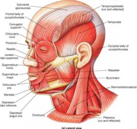
The electromyogram (EMG) is a bio-signal that associated with the electrical potential from human muscle. There are many ways to get the EMG, from moving one’s hand to moving one’s head, depending on a motion that associated with the use of one’s muscle. In my research, I have used mastication or biting motion as a way to produce EMG signal. To determine the EMG for the study, we need to understand which muscle used for bit-ing motion. The muscle used primarily is around one’s mouth. Usually, the muscle used Masseter, Buccinator, Zygomaticus minor/major and depressor anguli oris as shown in Figure 1. Human mastication or biting motion also depend on one age, race, area of reside and eating habit.
3. Research Equipment
3.1. Bio-Signals Instrument
Figure 1. Human face muscles (Ref.: http://www.advocurenf2.org/livingwithnf2_ailments+care_face.php).
Figure 2. NF instrument processor box (Left picture) and EEG head box with electrodes (Right picture).
3.2. uArmTM
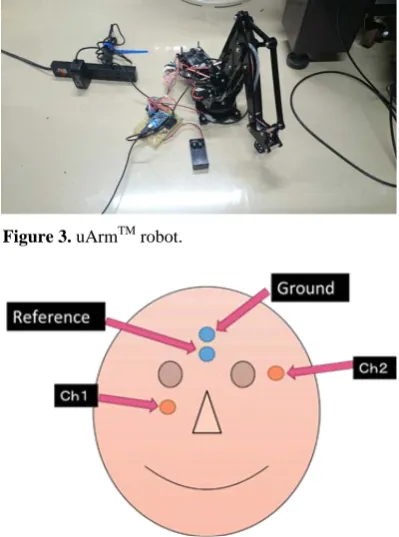
The robot used for the research is uArmTM robot as shown in Figure 3. The robot is made from u Factory company from China. The robot used 5 servo motor each motor use to control the motion function of the robot. The motion function consists of moving up and down the robot arm joint, stretch forward and backward robot arm joint, robot base rotation, robot gripper part rotation and gripping and releasing the robot gripper.
3.3. Visual Studio 2008 and Bio-Signals
Visual studio 2008 and 2010 express is a software that be used to program a 2010 Express instrument and device based on C/C++ programming language. In this study, the Visual Studio is used as a medium for programming the NF instrument for EOG and signal detection and recording. In addition the visual studio is used to program the uArmTM for EOG and EMG robot control system in C/C++ programming via serial communication.
4. Research Method
4.1. EOG Electrode Position
[image:3.595.145.483.378.468.2]Figure 3. uArmTM robot.
Figure 4. EOG electrodes position.
4.2. Experimental EMG Electrode Position
EMG signal could be derived by many way regarding human activities that using any muscle in one’s body. In this study we are using mastication or bite motion as a method to obtain the EMG signals as shown in Figures 5-8. In order to obtain those signal, the electrodes are positioned consequently with the face muscle that be used during the biting motion. The target face muscle for this study is Masseter, Buccinator, Depressor anguli oris, and Zygomaticus major/minor. The electrode will position on face skin proportional to the muscle mentioned. The electrode positions are changed for each section and the number of biting motion for each section is three times. The respective result of each muscle electrode position will be derived to find signal characteristic and pattern.
4.3. EOG and EMG Electrode Position
As we have determined the location of best location on EOG and EMG respectively, the next step of our study is to determine whether the both EOG and EMG electrode positions could be combined together and get the same signals result as done independently. Basically, 4 electrodes are used in the experiment, the electrode of Ch1 and Ch2 are specialize to detect and record EOG and electrode Ch3 and Ch4 are specialize for EMG. Each electrode position is given a code name perpendicular to their number of electrodes used to discriminate them. The me-thod of obtaining the EOG and EMG signals are the same, eye gazes motion and biting motion. Besides, the sampling rate is 100 Hz and the low-pass filter used for the experiment is 60 Hz. Each results are used to deter-mine the signals characteristic and pattern.
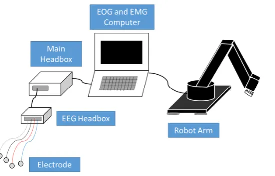
4.4. Robot Control System
Figure 5. Masseter EMG signal.
Figure 6. Buccinator EMG signal.
Figure 7. Depressor anguli oris EMG signal.
[image:5.595.212.419.408.538.2] [image:5.595.209.420.560.702.2]Figure 9. Robot control system.
5. Result and Discussion
5.1. EOG and EMG Electrode Position
In the combination of EOG and EMG electrode position, the signal recorded especially in Ch3 and Ch4 is unst-able and hard to be analyzed. In all experiment, the biting motion signal obtained similar to noise signal. In ad-dition, during doing eye gaze motion, all specialized electrode which used for detecting and recording EOG and EMG reacted to the motion. It is the as for biting motion, all specialized electrode reacted to the motion. Thus, the EOG and EMG signals are hard to discriminate for the robot control system.
From signal result obtained for all the electrode position, we realized that we do not many electrode to detect and record EOG and EMG signal. It is possible if only using EOG electrode position to detect and record both EOG and EMG signal as shown in Figures 10-12. The cut-off frequency for the low-pass filter should be lo-wered to 30 Hz in order to record EMG signal effectively.
5.2. EOG Discrimination Method
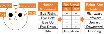
Based on the signals obtained, we could discriminate each gaze motions. The discrimination method for each gaze motions could be determined by the polarity of the first peak amplitude in Ch1 and Ch2 of the electrodes as shown in Tables 1 and 2.
5.3. EMG Discrimination Method
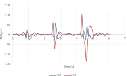
As for EMG signal we decided to use strong biting motion as medium to get EMG signal. Strong biting motion has higher magnitude of amplitude than other and has consistent signal result than other. The higher magnitude of amplitude and consistency of EMG signal are essential to discriminate the EMG than EOG signal.
The discrimination method for EMG signal, we done several strong biting motion experiment to investigate the signal characteristic and pattern. By the experiment done, the EMG signal can be discriminate using the Ch2 EMG signal as the Ch2 gave stable and consistent signal.
To discriminate the EMG signal as control input for robot control, we found that the sum and ratio of the sig-nal can be used for this. The sum and ratio of Ch2 EMG sigsig-nal is much higher in compare with the Ch2 EOG. Table 3 shows the polar peak amplitude of Ch2 EMG signal relationship with sum and ratio of the signal ob-tained. The equation for the sum and ratio of signal is derived as below.
Sum = |〖Ch2〗_max| + |〖Ch2〗_min| (1)
ratio = |〖Ch2〗_max/〖Ch2〗_min| (2)
where
〖Ch2〗_max = Positive Peak Amplitude
Figure 10. Up and down gaze motion signal.
Figure 11. Right and left gaze motion signal.
Figure 12. Biting motion strength signal. Left to right; small, normal and strong biting motion signal.
5.4. Robot Control
In this part, the EOG and EMG discrimination method is used to control the robot. The robot arm joint move-ments are determined by the EOG discrimination method where the polarity of eye gaze motion signals in each Ch1 and Ch2. The EMG discrimination method is used to control arm gripper to grasp and release the target ob-ject. In the robot control experiment, we are successfully control the uArm robot by using both EOG and EMG discrimination method as the control input.
6. Conclusions
[image:7.595.206.423.366.495.2]Up Down Right Left
Ch1 + − − +
Ch2 + − + −
[image:8.595.190.410.82.155.2]Table 2. EOG peak amplitudes from 4 EOG gaze motions.
Table 3. EMG peak amplitudes from strong bite EMG.
Together with the signal patterns, we now can create a control system using EOG and EMG signal respec-tively. The EOG signals are used as robot joint angle movement control and EMG is used for controlling the de-gree of gripping.
References
[1] Cristian-Cezar, P., Florin, G. and Doru, T. (2012) EOG-Based Visual Navigation Interface Development. Expert Sys-tems with Application, 9, 10857-10866.
[2] Deng, Y.L., Hsu, C.L., Lin, T.C., Tuan, J.S. and Chang, S.H. (2010) EOG-Based Human-Computer Interface System Development. Expert Systems with Application, 37, 3337-3343. http://dx.doi.org/10.1016/j.eswa.2009.10.017
[3] Lledo, L.D., Ubeda, A., Ianez, E. and Azorin, J.M. (2013) Internet Browsing Application Based on Electrooculography for Disabled People. Expert Systems with Applications, 40, 2640-2648. http://dx.doi.org/10.1016/j.eswa.2012.11.012 [4] Bera, R., Boquete, L., Mazo, M. and Lopez, E. (2002) Wheelchair Guidance Strategies Using EOG. Journal of
Intelli-gent and Robotic Systems, 34, 279-299. http://dx.doi.org/10.1023/A:1016359503796
[5] Eduardo, I., Jose, M.A., Eduardo, F. and Andre, U. (2010) Interface Based on Electrooculography for Velocity Control of a Robot Arm. Applied Bionics and Biomechanics, 7, 199-207. http://dx.doi.org/10.1155/2010/813184
[6] Sasaki, M., Ito, S., Takeda, K., Okamoto, T. and Rusydi, M.I. (2013) Developing a Two-Link Robot Arm Controller Using Voluntary Blink. Proceedings of the 22nd MAGDA Conference, Miyazaki, December 2013.
[7] Rusydi, M.I., Okamoto, T., Ito, S. and Sasaki, M. (2014) Rotation Matrix to Operate a Robot Manipulator for 2D Ana-log Tracking Object Using ElectroocuAna-lography. Robotics, 3, 289-309. http://dx.doi.org/10.3390/robotics3030289 [8] Rusydi, M.I., Mori, Y., Okamoto, T., Sasaki, M. and Ito, S. (2012) Using EOG Signal to Control Manipulator.
Pro-ceedings of the 7th Asia Pacific Symposium on Applied Electromagnetics and Mechanis, Ho Chi Minh City, July 2012. [9] Rusydi, M.I., Sasaki, M. and Ito, S. (2014) Affine Transform to Reform Pixel Coordinate of EOG Signals for
Control-ling Robot Manipulators Using Gaze Motions. Sensor, 14, 10107-10123. http://dx.doi.org/10.3390/s140610107 [10] Okamaoto, T., Sasaki, M., Ito, S., Takeda, K. and Rusydi, M.I. (2013) Using Gaze Point and Blink Detection to
Con-trol Robot Arm by Use of the EOG Signal. Proceedings of the 22nd MAGDA Conference, Miyazaki, December 2013. [11] Rusydi, M.I., Sasaki, M. and Ito, S. (2014) Calculate Target Position of Object in 3-Dimensional Area Based on the
[image:8.595.183.411.197.248.2] [image:8.595.185.416.345.387.2]