Page 38
Optimal Power Allocation
and Power Control Parameter in OFDM-Based
Cognitive Radio Systems
Nguyen Van Vinh
1, 2, aand Yang Shouyi
1, b1
School of Information Engineering, Zhengzhou University, China
2
Hungyen University of Technology and Education, Vietnam
Abstract: In orthogonal frequency division multiplexing (OFDM)-based cognitive radio (CR) systems, the optimized algorithms for sub-carrier power allocation face the problems of complex iterative calculation and difficult realization. In this paper, we propose an exponential power distribution function and derive a sub-optimal power allocation algorithm. This algorithm aims to allocate power of in-band subcarriers of cognitive users according to the numerical characteristics of the power distribution function by using a convex optimization numerical method under linear constraints. This algorithm has the advantages of fast calculation speed and easy realization, and reduces the interference to the authorized users, which is caused by the power leakage of the in-band subcarriers of cognitive users to the out-of-band subcarriers. Simulation results show that the proposed algorithm maximizes the in-band channel capacity of the cognitive users under certain interference thresholds of the authorized users, thus increasing their transmission rate.
Keywords: Orthogonal Frequency-Division Multiplexing (OFDM); Cognitive Radio (CR); Power Allocation; Linear Water-Filling; Convex Optimization.
I. INTRODUCTION
Due to the rapid growth of wireless communication, the available resources of wireless spectrums are becoming scarcer, impeding the application of new techniques. Cognitive radio (CR) has been widely accepted as an effective method to improve wireless spectrum utilization [1]. It can perceive and detect the dynamic changes of idle wireless spectrums, and make the unused spectrum available to cognitive users. The CR system must not affect the normal communications of the license users (LUs). The cognitive users (CUs) can communicate with each other by automatically searching and utilizing the idle spectrum. Therefore, CR is the most effective way of solving the problem of spectrum scarcity [2].
As a universally acknowledged technology of the next generation of broadband wireless communication networks, orthogonal frequency division multiplexing (OFDM) technology can improve significantly the performance of
cellular systems by utilizing the characteristic of multiuser diversity to distribute the sub-channels, bits and power effectively, and is regarded as an ideal alternative technology of realizing CR systems [3]. CUs can neatly fill the idle spectrum left by LUs, by taking advantage of the OFDM technology. The fast Fourier transform (FFT) module in the receiver can be used for spectrum perception.
the design problem is that, given an interference threshold prescribed by the primary users, how much power each CR user’s subcarrier should have, so thatthe transmission rate of CR users could be maximized. In [7], the authors proposed an optimal power allocation scheme using Lagrange formulation. This scheme maximizes the downlink transmission rate of CUs, while keeping the interference induced to the primary users below a threshold. However, the total power constraint was not considered in this paper.
In this paper, we propose a modified power allocation function mentioned in [7]. In particular, we propose an exponential power distribution function, rather than a linear function, with the purpose of optimizing the channel capacity at the CU band. Simulation shows that our proposed sub-optimal power allocation algorithm provides the channel capacity being better than that in [7], and is close to the optimal channel capacity. Moreover, to satisfy the interference constraint of CU on LU, this paper sets up an optimization problem of maximizing the CU channel capacity under the condition of the interference constraint in LU receiver. Moreover, when the SNR of LU changes, CU can adjust the transmitting power of CU adaptively according to the power control parameter η of LU interference constraint, and then maximize the CU channel capacity. By using lagrangian multiplier method, the optimal solution of this mathematical problem can be obtained.
This paper is organized as follows. Section II presents the system model and formulates the studied problem as a convex optimization problem. Section III introduce power control parameter and illustration of the power control parameter η along with SNR of LU. In Section IV and V, we propose a sub-optimal power allocation algorithm, which is based on an exponential distribution function, examine its two particular cases and examine subjects. Section VI provides the numerical simulations and discussion, and Section VII concludes the paper.
II. SYSTEM MODEL
This text considers the downlink of a CR system. According to how the IEEE 802.11a system model [4] utilizes the OFDM modulation technique, we suppose the disposition of LU band and the idle spectrum which CU insert is shown in Fig.1.
Fig.1. Distribution of license and cognitive users
Suppose that the LU's bandwidth is B, and CU is separated on either side of LU. The interval of every subcarrier in the CU band, and the interval between LU band and CU band are both ∆f. The sum of subcarriers in the band of CU is N. Because the OFDM modulation mode is used in both the CUs and LU (the attenuation characteristic of power spectral density side lobe), the LU and CUs both interfere with each other.
Interference Introduced by Cognitive User's Signal
According to S. Haykin [1], the power density spectrum (PSD) of the ithsubcarrier in CR user band can be written as
(1) where Pidenotes the transmitting power of subcarrier iin
the CU band, Ts denotes the symbol period of OFDM.
Therefore, the interference power of the ithsubcarrier in the CU band to the LU band is:
df
fT
fT
T
P
P
d
I
i BB i d d s s s i i i i i
/22 / 2
)
sin
(
)
,
(
(2) (3) Eq. (2) can be written asi i i i
i
d
P
P
K
I
(
,
)
(4)Interference Introduced by License User's Signal
2
)
sin
(
)
(
s s s i ifT
fT
T
P
f
df
fT
fT
T
K
i BB i d d s s s l i
/22 / 2
)
sin
(
LU B f CUs Δf N/2 (N/2)-1 N/ 2 1 2 CUs ΔfPage 40
The interference power of LU signal after the M-fast Fourier transform (FFT) processing to subcarrier i in CU band is:(5)
where LU(f ) denotes the PSD of the LU signals, and PLUdenotes power of the LU signals.
Channel Throughput Analysis of CUs
Assuming that each subcarrier goes under frequency flat fading and the instantaneous fading gains are perfectly known at the transmitter. The transmit power adaptively loaded in each CR user’s subcarrier. With an ideal coding scheme, the transmission rate at the ithsubcarrier, Rifor the
transmit power, Pi and channel fading gain hi is connected
via the Shannon capacity formula and is given by [7]:
(6)
where
i2is the sum power of Gaussian noise and the interference caused by PUs on the ith subcarrier.
is a constant signal-to-noise ratio (SNR) gap, according to [8],
has a relationship with the required bit error rate (BER):)
)
1
(
2
3
exp(
5
1
M
BER
i(7) where i i i i i
J
P
h
22
(8)It is defined as signal to interference noise ratio (SINR), hiis channel gain, δi2is channel noise variance. We have
ii
M
(
)
1
(9)The throughput can be deduced
)
1
(
log
)
,
(
2
i i ii
p
h
R
(10)where
)
5
ln(
5
.
1
BER
(11)III. INTRODUCE POWER CONTROL PARAMETER In Ref. [9], the author confined the CU maximum transmitting power on the basis of LU's SNR, where adjust the LU tolerable interference limitation by using power control parameter η, then conduct power allocation when satisfy the interference constraint condition to LU. According to the channel status of LU link, the power control scheme includes the following 3 situations:
Situation I: When LU interrupts communication because of the poor condition of the channel, CU is immune to the interference constraint of LU, where η=1. Now CU can be trans-mitted at maximum power. Therefore, LU's interference threshold Ith is related to CU's maximum
transmitting power and the interference channel gain between CU and LU.
Situation II: When LU is in normal communication condition, CU must control the maximum transmitting power according to LU tolerable interference limitation, at this moment 0 <η< 1.
Situation III: When the LU channel SNR is high enough, the LU is impossible to break off even if CU is transmitted at maximum power. Now η =1 and cognitive users can be transmitted at maximum power.
To avoid the interruption in LU normal communication, the value of ηshould be confirmed according to LU channel status messages when allocate power. First we define the SNR of LU is
2 2 L L L L
P
h
(12)Accordingly, signal to interference noise ratio (SINR) of LU is defined as
df
f
T
P
d
I
i BB i d d LU s LU i LU
/22 2 L th L L LC
I
P
h
(13)Where hi is the channel gain of licensed link, δ
2
is additive white Gaussian noise (AWGN) power in LU band. When LU is in normal communication status, CU should conduct strict power control on the basis of η. Suppose the licensed link is in normal communication status (the transmission capacity is RL.), the SINR of licensed link has
to satisfy the following qualification
1
2
)
(
2 2
RLL th L L LC
I
P
h
(14)Therefore, ηmust satisfy
)
1
2
(
1
2 2 L R L L th LP
h
I
(15)Hence, ηcan be shown as
L L L La
b
a
b
a
b
b
a
a
b
1
,
1
1
,
,
1
(16) where
th L R th LI
b
I
a
L 2 2)
1
2
(
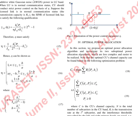
(17)Figure 2 shows the changing status of the power control parameter ηalong with SNR of LU, where the turning point (b/a, (1+b)/a)of the disturbance control curve depend on RL.
Therefore, once the transmitting capacity RLof licensed
[image:5.612.20.568.178.641.2]link is fixed, the disturbance control curve is fixed therewith. So the value of ηcan be determined according to γL.
Fig.2. Illustration of the power control parameter η. IV. OPTIMAL POWER ALLOCATION
In this section, we propose an optimal power allocation algorithm and investigate its two suboptimal power allocation algorithms, which are less complex and easier to be realized. Note that the optimal CU’s channel capacity can be found based on the following optimization problem
N i i i iP
R
P
h
C
i 1,
max
(18)
0
,
,
.
.
1 2 2 1 1 1 i N i th i i i N i th i i iP
I
P
d
I
I
P
d
I
t
s
(19)where C is the CU's channel capacity, N is the total number of subcarriers in the CU band, Riis the transmission
rate at the ith subcarrier, and the interference thresholds prescribed by the left and right primary bands are equal, e.g.
.
2 1
th th
th
I
I
I
A. OPTIMAL POWER ALLOCATION SCHEME
η
γ
1
0
I
II
III
Page 42
For the above optimization problem, although the objective function is a concave function, the constraint condition is linear. Thus, the optimization problem is a convex optimization problem, and the convex optimization approach can be used to analyze the optimal power allocation scheme. We use Lagrange multiplier method to construct the Lagrange function:.
)
,
(
)
,
,
(
1 1 21
N i i i ii
R
P
h
P
L
2 1 2 2 1 1 1)
,
(
)
,
(
.
th N i i i i th N i i ii
d
P
I
I
d
P
I
I
(20) where 1and 2are the Lagrange constraints,
1,
2
0
.Therefore, the derivative of Eq. (21) is
i i i i i i i
P
I
P
I
P
h
P
L
2 2 1 1 2 21
(21) where;
2 2 LU i
I
/22 / 2
sin
B d B d S S S i l i l i i idf
fT
fT
T
P
I
K
The right side of Eq. (22) is equal to zero. Thus, the optimal transmit power can be obtained as:
2 222 1 1
1
i i i i ih
k
k
P
(22)where (x)+= max (0, x) and Lagrange multiplier
1,
2 can be Eq. (22) are obtained:(23)
From equation (23), we can see that the power is assigned to the ith carrier of the CU band may appear less than zero. Therefore, here carried out the processing and analysis steps iterative partitioned water filling (IPW) algorithms. After much choice and change of operator until the allocated power on each carrier is non-negative and positive in the CU band [10].
B. SUBOPTIMAL SCHEMES
By using the above scheme, we can calculate the optimal power allocation policy that maximizes the transmission capacity of the CR user while keeping the interference introduced to the Pos below the specified threshold. However, the complexity of the optimal scheme is high and hence, in the following section, we propose suboptimal schemes based on heuristics that have lower complexity.
In the scheme optimized power allocation, the number of carriers in the CU band needs to be adjusted from left to right are 1 , 2, 3, …, (N /2)-1, N/2, N/2, (N/2)-1, …, 3, 2, 1, where Nis an even number; Similarly when Nis odd. In [7] proposed optimization scheme A and B. The authors proposed schemes C and D, based on power allocation functions exponential.
1) SCHEME C
In this scheme, determination of the maximum power can be allocated in each subcarrier is different. We divide the total interference on the number of the available subcarriers, and equal interference threshold per subcarrier will be determined. In this way the maximum power that can be allocated to each subcarrier will be:
N
i
i
p
P
iC
1.5,
1
,
2
,
3
,...,
(24)where pwill be determined by the value of Ith. From (23)
and (24), the maximum power can be written as
(25)
2) SCHEME D
The classic OFDM loading algorithms: uniform power loading and water filling schemes are suboptimal for such an interference-limited scenario as they do not have any constraint on the interference. Therefore, for a given interference threshold Ith, power allocated to the i
th
subcarrier with the proposed exponential power loading can easily expressed as:
N
i
i
p
P
iD
3.0,
1
,
2
,
3
,...,
(26) where pwill be determined by the value of Ith. From (23)and (26), the maximum power can be written as
0 . 3 1 0 . 3
i
K
I
i
P
N i i th D i
(27) OPTIMAL POWER CONTROL PARAMETER After the power control parameter η is introduced, to maximize CU's channel transmission throughput, the problem can be modeled as.
N i i i iP
R
P
h
C
i 1,
max
(28)
0
1
0
.
.
1 1 i N i total i N i th i iP
P
P
I
k
P
t
s
(29)Where C denotes CU's channel capacity, N denotes the total number of subcarrier in CU band, I denotes LU's
endurable maximum interference limitation, Ptotal denotes
CU's transmitting total power.
For the above optimization problem, although the objective function is a concave function, the constraint condition is linear. Thus, the optimization problem is a convex optimization problem. And the convex optimization approach can be used to analyze the optimal power allocation scheme. We use lagrangian multiplier method to construct the lagrangian function.
N i i iP
L
1 2 21
,
)
log
(
1
)
,
(
)
(
)
(
1 2 11
N i total i N i th ii
k
I
P
P
P
(30)
where
1,
2
0
Subpower allocation of different algorithm
0
)
,
,
(
1 2
i ip
P
L
(31)Thus, the optimal transmit power can be obtained as
(
log
(
2)
)
2 2 1 2 * i i i i i
h
J
k
e
P
(32)where (x) + = max (0, x) and lagrangian multiplier
1, 2
can be figured out on the basis of the above constraint condition.V. SIMULATION RESULTS
To highlight CU's influence on communication interrupt of LU, which means to ascertain the effect of disturbance control parameter in CU communication, this text only consider the performance index concerned with situation II in the stage of simulation analysis. For estimating the performance of optimal power allocation decision, this text compares with the equal ladder scheme and average allocation scheme mentioned in Ref. [7].
Page 44
In our simulations, we suppose the values of Ts, f and Bto be 4 µs, 0.3125 MHz, 0.3125 MHz respectively. The total number Nof sub-carriers in CU channel is 12, which means there are six subcarriers in each side of the LU channel (it is similar when N is an odd number). Power of the channel corresponding to each subcarrier in the LU band is created randomly within [1, 10] µW. The white Gaussian noise in the LU channel is 10 µW, the interference threshold (Ith) is
3.2 mW. The total transmitting power of the CU channel is 1 W. The BER = 10-3is considered in all simulations except the last one. Perfect channel state information (CSI) is assumed at both transmitter and receiver.
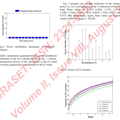
Fig. 3 presents the power distribution histograms of the aforementioned five power distribution methods [11]. Intuitively, a good power allocation will allocate more power to both sides of the CU band to overcome the interference effect from the LU band.
TAB.1. THE POWER VALUES OF DIFFERENT OPTIONS SCH
The schemes
The values subcarrier
1 2 3 4 5 6 7
Opt. scheme 5.1e-19 31.43 64.41 96.91 202.87 334.15 332.27
[image:8.612.22.586.117.700.2]Fig.3. Power distribution histograms of different schemes
Table Isummarizes quantitatively the power distribution per subcarrier of the five schemes shown in Fig. 2. Clearly, the transmission powers of the sub-carriers in the CU band are inversely proportional to the distance to the LU band.
Fig. 4 presents one example realization of the channel power (i.e. |hi|
2
) corresponding to the 12 subcarrier of the CU band. These values are 0.3293, 0.4261, 1.3712, 2.1310, 2.1909, 1.7106, 0.7362, 1.3674, 0.8638, 1.7524, 0.4715, and 0.5771 dBµ respectively. Again, these values are random created within the range [1, 10] µW.
[image:9.612.35.541.196.701.2]Page 46
Fig.5. Maximum transmission rate of CUs underdifferent interference thresholds
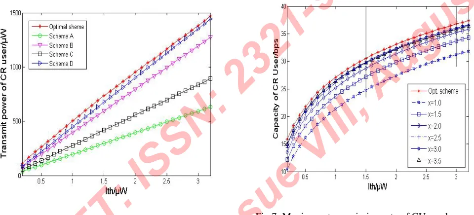
In Fig. 5, we plot the achievable capacity of CUs versus the interference threshold introduced to the primary user band for different schemes. We can see that capacity in all schemes increases as the interference threshold increases. In addition, the channel capacity of Scheme D is very close to the channel capacity of the optimal power allocation scheme, while having lower complexity. The channel capacity in Scheme D is higher than that in the two schemes A and B proposed in [7].
Fig.6. Maximum transmission power of CUs under different interference thresholds
Fig. 6 presents the transmit power of the CUs versus the interference threshold introduced to the primary user’s band for various schemes. Clearly, the optimal scheme allows us to transmit higher power than the other schemes for a given interference threshold, as the optimal scheme considers interference in its power loading policy for a given interference threshold. Again, it can be observed that, for a given interference threshold, the transmission power in the proposed scheme D is close to that in the optimal scheme, and is significantly higher than that in the two schemes A and B.
In Fig. 7 and 8, we examine the channel capacity of the CU channels in our proposed suboptimal scheme D in comparison with that in the optimal power allocation
scheme, using the same simulation parameters and conditions mentioned in the previous simulation results, except that the exponent, denoted as x,takes different values 1.0, 1.5, 2.0, 2.5, 3.0, and 3.5. In particular, Fig. 7presents the channel capacity of CUs in our proposed power allocation scheme D with different exponential distributions with different values of the exponent, while Fig. 8magnifies Fig. 7for the two example ranges of interference thresholds 1.45≤ Ith≤ 1.55 and 2.95≤ Ith≤ 3.05. From Fig. 7and 8, one
[image:10.612.34.514.277.495.2]can see clearly that the proposed scheme D with the exponent of 3.0 has the best performance for the whole considered range of interference thresholds.
Fig.8. Magnification of Fig.7 in the interference threshold ranges 1.45≤ Ith≤ 1.55 and 2.95≤ Ith≤ 3.05
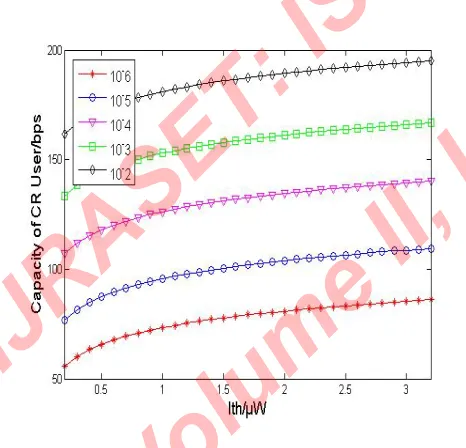
Fig. 9 presents the channel capacity corresponding to different values of BER = 10-2, 10-3, 10-4, 10-5, and 10-6. Other parameters are kept the same as above. We can see that the channel capacity increases significantly when the BER requirements are more relaxed. The channel capacity at BER = 10-2 almost doubles the channel capacity at BER = 10-5.
Fig.9. Channel capacity vs. power interference threshold of CUs with different BERs from 10-6to 10-2
Fig. 10, demonstrates that the maximum transmission rate of these power allocation schemes all increases along with the augment of power control parameter η, and the maximum transmission rate of optimal scheme is superior to that of the other schemes. The bigger the power control parameter η, i.e. which means the transmission capacity of licensed link is higher, the transmission capacity in CU channel is higher.
Fig.10. Maximum transmitted data rate of CU vs. power control parameter
VI. CONCLUSIONS
[image:11.612.31.256.118.294.2] [image:11.612.294.549.210.430.2] [image:11.612.23.256.440.664.2]Page 48
power allocation algorithms under the effect of LU and CU guard bands.REFERENCES
[1] S. Haykin, Simon, “Cognitive radio: Brain-Empowered Wireless Communications,” IEEE Journal on Selected Areas in Communications, vol. 23, pp. 201-220, Feb. 2005.
[2] Akyildiz I. F., Won-YeoI Lee, Vuran Mehmet C., Mohanty S., “Next generation, dynamic spectrum access, cognitive radio wireless networks, a survey,” Computer Networks of Elsevier, vol. 46, pp. 40-48, April. 2008.
[3] Weiss T. A, Jondral F. K, Spectrum pooling, “An innovative strategy for the enhancement of spectrum efficiency,” IEEE Communications Magazine, vol. 42, pp. S8-14, Mar. 2004.
[4] Weiss T, Hillenbrand J, Krohn A, Jondral, F.K, “Mutual interference in OFDM-based spectrum pooling Systems,” Proc. IEEE Vehicular Technology Conference Spring, IEEE Press, vol. 4, pp. 1873-1877, 2004.
[5] G. Bansal, M. J. Hossain, V. K. Bhargava, “Optimal and Suboptimal power allocation schemes for OFDM-based cognitive radio systems,” IEEE Transactions on Wireless Communications,vol. 7, pp. 4710-4718, Nov. 2008.
[6] Wyglinski, Alexander M., “Effects of bit allocation on non-contiguous multicarrier-based cognitive radio transceivers,” Proc. IEEE Veh. Technol. Conf., pp. 1-5, Sept. 2006.
[7] G. Bansal, M. J. Hossain, V. K. Bhargava, “A daptive power loading for OFDM-based cognitive radio systems,” Proc. IEEE ICC, IEEE Press,pp. 5137-5142, 2007.
[8] G. J. Foschini and J. Salz, “Digital communications over fading radio channels,” Bell Syst. Tech. J., pp. 429-456, Feb. 1983.
[9] Y Chen, Y Zhao, “On cognitive radio networks with opportunistic power control strategies in fading channels,” IEEE Transactions on wireless communications, vol. 7, No. 7, pp. 2752-2761, July 2008.
[10] Wang P, Zhao M, Xiao L, “Powerallocation in OFDM-based cognitive radio systems”, Proc. IEEE Global Communication Conference, IEEE Press, pp. 4061-4065, 2007.
![Fig. 3aforementioned five power distribution methods [Intuitively, a good power allocation will allocate more power to both sides of the CU band to overcome the interference presents the power distribution histograms of the 11]](https://thumb-us.123doks.com/thumbv2/123dok_us/8587487.862846/8.612.22.586.117.700/aforementioned-distribution-intuitively-allocation-interference-presents-distribution-histograms.webp)