Design and Fabrication of Reverse Gear
Mechanism for Handicapped People
Prof. Vinod Nirale1, Prof. V.S. Konnur2,Shivaraj Bagewadi3
1,2 Assistant Professor, Mechanical Engineering BLDEACET Vijaypur, VTU Belgaum
3Student, Mechanical Engineering, BLDEACET Vijaypur, VTU Belgaum
Abstract: In the present scenario, there were no mopped vehicles equipped with reverse gear facility. So it is very difficult for a handicapped person while the vehicles front wheel gets into a trench as well as in the case of parking. The main objective of this paper is to facilitate ‘comfort ability and safety’ to the physically challenged people where it requires a motor vehicle, lever, reverse gear box, v-belt, sprocket and other necessary parts. When there is a need to reverse the vehicles they can engage the hand lever for reverse gear, the vehicle moves backwards. This reverse gear mechanism provides a simple, low cost revers transmission system which will be helpful for handicapped people.
This paper explains how a reverse gear mechanism, with portable gear box of four gears are used for obtaining reverse motion that can be easily operated by hand. This reverse gear mechanism provides a simple, low cost reverse transmission system which
will be helpful for handicapped people.
I. INTRODUCTION
The handicapped people facing many problems related to their transportation, there is need to help them for their easy convenience
for travelling. Presently, handicapped people drive two wheelers with extra support wheels They face difficulty in reversing the
vehicle while travelling, By using this mechanism the handicapped people can easily move the vehicle backward. At present, there is no system available to back the vehicle. Automobile is a vehicle driven by an internal combustion engine and it is used for transportation of passengers and goods on the ground. Automobile can also be defined as a vehicle which can move by itself. At times when the front wheel gets into a trench it is very difficult to take the vehicle from parking. Even normal people face much problem to take the vehicle out of the parking at that time. In case of the handicapped people who drive two wheelers with extra support wheels, face much problem to take the vehicle out of the parking by pushing the vehicle with legs as we do. In order to take the vehicle out of the parking they need to seek others help or they should push it out of the parking.
As a help to them we have designed a gear box which will be fit to the vehicle. It is fitted to the side of the vehicle and helping in the backing of the vehicle. When the driver wants to move the vehicle backward what he needs is just to move the rod in the newly designed gear box in one direction and when the driver wants the vehicle to move in the forward direction, then the rod is to be moved to the earlier position. The change of direction of the vehicle is just by the movement of the gear rod.
II. LITERATURE REVIEW
As a design do not get directly related design with this work. This uses gear box system designed, such as the control and stability analysis of to wheeled road vehicles by “ simosevangelou ” he worked on control and stability of vehicles also this control and stability is the main thing to move back word.
Design and study of four speed sliding mesh gear box by “Artehur Mani Anta Reddy 1, Akash.k2 ” 12 department of mechanical engineering, R.M.K. Engineering college, Anna University, Chennai, India he works on gear box but not for reverse gear. The purpose of transmission is to provide natural, forward gear speeds or ranges and reverse. They must be able to provide a gear ratio that is low enough, when multiplied with the final drive ratio to increase the engines torque sufficiently to accelerate the vehicle at the desire rate. Reverse might be roughly the same ratio as first since vehicle will be starting from a stop in both cases (Birch T. and Rockwood C. 2007).
For any given vehicle, transmission gear ratio is selected to satisfy performance requirements of edibility, fuel economy, acceleration and ease of operation. Fuel economy consideration are essential the selection of gear ratio. Basically too high a gear ratio causes the engine to run too fast and thus, failing to operate at optimum fuel efficiency. Otherwise, an extremely low numerical gear ratio will be affecting the vehicle performance such as acceleration. Hence, Acceleration is also important concern in gear ratio selection. To maximize acceleration gear ratio should be selected such that up shifts only when the next higher gear will provide more torque to the drive wheels (Razzcki S.T., Troy, and MI 2004) providing maximum torque to the drive wheels in each gear requires consideration of ratio steps. Wide ratio steps in the lower gear provide for more fuel efficiency due to less frequent shifting (Razzcki S.T., Troy, and MI 2004). However, shifting through wide ratio steps will requires skill full technique otherwise it can cause a loss in fuel efficiency. a transmission first consist a first a first mission mechanism and a second.
Transmission mechanism, when a clutch is in an engaged state, the first transmission mechanism transmits a driving force from the engine to the excel shaft. When a clutch is in disengage state, the second transmission mechanism transmits a driving force from the engine to the axle shaft ( yaqui Y. And Saitama (JP) (2006)). Usually, transmission will have multi gear ratios or simply gears, with the ability to switch between them as a speed varies.
This switching may be done manually by the operator or automatically. Directional forward and reverse control may also be provided. Single ratio transmissions also exist which simply change the speed and torque and sometimes direction of motor output. In motor vehicle applications the transmission will generally be connected to crankshaft of the engine.
III. COMPONENTS
In the manufacture of mechanical parts, knowledge of material properties, cost, design concepts and their interactions is required. The large number of available materials, together with the complex relationships between the various selection parameters, often makes the selection process a difficult task. When selecting materials, a large number of factors must be taken into account.
These factors are mechanical properties, physical and electrical properties, corrosion resistance, environmental friendliness and economy. In mechanical design, however, mechanical properties are the most important. The most important mechanical material properties usually encountered in material selection process are fatigue strength, tensile strength, yield point, hardness, stiffness, toughness, creep resistance and density. After analyzing the following concepts we have chosen material for the gear as 40Ni 2Crl Mo 28. It is the one of the suitable that can be used for the production of the gear. It is very much cheaper and has a good manufacturability.
For the reverse gear mechanism it uses different components. Following are the essential components listed below,
A. Spur Gear
B. Ball Bearin
C. Stepped Shaft
D. Washer
E. Selector Ring and Fork
G. Sprocket and Chain
H. Nut and Bolts
I. Wheels
IV. METHODOLOGY
[image:4.612.167.428.115.279.2]A. Working principle
Fig. 4.1 Forward Gear Arrangement
The principle applied to this project is a gear transmitting is power in opposite direction. When an intermediate gear is introduced between these two gears the intermediate gear will change the direction of rotation of the final gear or drive.
B. Basic law
Here we law of gearing as the most important law used in our project
V= rAωA= rBωB
Where input gear A with radius and angular velocity ωA meshes with output gear B with radius r and angular velocity ωB.
Therefore,
ωA/ωB = TB / TA = NB / NA .
Where NA is the number of teeth on the input gear and NB is the number of teeth on the output gear.
The mechanical advantage of a pair of meshing gears for which the input gear has NA teeth and the output gear has NB teeth is given
by
MA =TB / TA = NB / NA
This shows that if the output gear GB has more teeth than the input gear GA, then the gear train amplifies the input torque. And, if the output gear has fewer teeth than the input gear, then the gear train reduces the input torque.
C. Construction
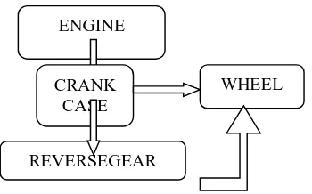
Fig. 4.2 Schematic Diagram of Reverse Gear Mechanism
The power transmitted from the IC engine to the crankcase and that to the rear sprocket which is coupled to the gearbox chain arrangement is used to transmit the power or the rotational speed generated at the crankcase is usually transmitted with standard velocity ratio to the wheels to have a forward motion in this project velocity ratio is attained to be unity while forward motion of the wheels a proper arrangement of gear is made also to have reverse motion and the same path is followed to transmit power to the
ENGINE
CRANK CASE
REVERSEGEAR
[image:4.612.225.400.535.644.2]wheels with a velocity ratio with respect to velocity ratio of forward motion
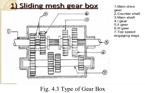
[image:5.612.188.423.119.270.2]D. Type of gear box
Fig. 4.3 Type of Gear Box
Gear box consist of number of shafts mounted parallel and gear on it, looks like a box of gears. In this case power transmission from one shaft to another shaft via gear is achieved by sliding of gear along the length of the shaft on which it is mounted, by this conjunction which will mesh with multiple gears. To have rotation in both the directions about the shafts.
E. Selection of Materials
The gear material should have the following properties
1) High endurance strength to withstand dynamic loads
2) Low coefficient of friction
3) Good manufacturability
4) High tensile strength to prevent failure against static loads
Generally cast iron, steel, brass and bronze are preferred for manufacturing metallic gears with cut teeth. Where smooth action is not important, cast iron gears with cut teeth may be employed. Commercially cut gears have a pitch line velocity of about 5metre/second. For velocities larger than this, gear sets with non-metallic pinions as one member are used to eliminate vibration and noise. Non-metallic materials are made of various materials such as treated cotton pressed and moulded at high-pressure, synthetic resins of the phenol type and rawhide. Moisture affects rawhide pinions. In the manufacture of mechanical parts, knowledge of material properties, cost, design concepts and their interactions is required. The large number of available materials, together with the complex relationships between the various selection parameters, often makes the selection process a difficult task. When selecting materials, a large number of factors must be taken into account.
These factors are mechanical properties, physical and electrical properties, corrosion resistance, environmental friendliness and economy. In mechanical design, however, mechanical properties are the most important. The most important mechanical material properties usually en-countered in material selection process are fatigue strength, tensile strength, yield point, hardness, stiffness, toughness, creep resistance and density.
F. Working of reverse gear mechanism
A gear train is a mechanical system formed by mounting gears on a frame so that the teeth of the gears engage.
Gear teeth are designed to ensure the pitch circles of engaging gears roll on each other without slipping, providing a smooth transmission of rotation from one gear to the next.
The transmission of rotation between contacting toothed wheels can be traced back to the Antikythera mechanism of Greece and the south-pointing chariot of China. Illustrations by the Renaissance scientist Georgius Agricola show gear trains with cylindrical teeth. The implementation of the involute tooth yielded a standard gear design that provides a constant speed ratio.
V. WORKING
this problem the vehicle is made to run in forward as well as in reverse direction. So, the reverse mechanism is achieved by proper design of rear gear box.
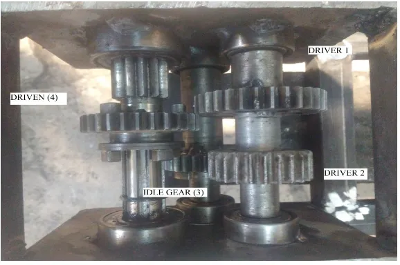
[image:6.612.155.444.120.312.2]The below figure shows the proper design of a gear box.
Fig. 5.1 Sliding Mesh Type Gear Box
Numbering of these gears for the calculation purpose, On the basis of Driven gear (4) the remaining three gears are selected and they are ,
A. Larger driver gear – it is denoted as gear 1.
B. Smaller driver gear – it is denoted as gear 2.
C. Idle gear – it is denoted as gear 3.
By this one can able to notice that the Dimensions of driven gear (4) and the smaller driver gear (2) are same, however as per the selection of gears with respective driven gear (4) the dimensions of the driver (2) must and should have to meet the dimensions of driven gear (4) to achieve the velocity ratio 1 for a forward motion of the vehicle The gear box consists 3 shafts with spur gears mounted on them, namely driver, idle and driven gear. The driver shaft consists of 2 spur gears of different size and which are rigidly mounted on it and this shaft is connected to sprocket just outside of the gear box, the sprocket is powered by engine of the vehicle. An idle gear is mounted on shaft rigidly and this assembly is mounted in gear box just below the driver gear shaft so that, idle gear mesh with driver gear. The idle gear acts as inter mediator between driver and driven gears. At last the gear box consists of a driven shaft with external teeth’s on it over a small length. A spur gear with selector ring and fork is mounted on the driven gear shaft so that, it can be moved along the shaft within gear box with the help of selector ring. This assembly of driven gear shaft is mounted in gear box so that, driven gear will mesh with idle gear and also with larger driver gear, this is achieved by movement of selector ring within the gear box. And this movement of driven gear with selector ring is achieved by lever, which is welded to the selector ring and exposed to the operator to operate in order to have a reverse and forward motion.
mess larger driver gear by operating with gear lever. During operation, driven gear will run reverse to the driver gear. As the IC engine drives the sprocket in forward direction, the driver shaft also run in the same direction but driven gear shaft will run in reverse direction, resulting in reverse motion of the vehicle. Then driven gear is made to move and mesh with idle gear by operating gear lever. During operation driven gear will run in the same direction of driver gear. As IC engine drives the sprocket in forward direction , the driven gear also run in forward direction, as idle gear is in contact with driver gear starts to rotate in reverse direction thus driven gear will run in forward direction, resulting in forward motion of the vehicle.
VI. CALCULATIONS
A Velocity Ratio
If engine runs the sprocket at 500 rpm i.e., N1=500 rpm i.e., =N2
Where 1- larger driver gear of PD = 5.75 cm 2- Smaller driver gear of PD = 5.1 cm 3- Idle gear of PD = 4.3 cm
4- Driven gear of PD = 5.1 cm
1) For Forward Motion
N2/N3 = D3/D2 N3=N2*(D2/D3)
N3= 500*(5.1/4.3) = 593 rpm
N3/N4 = D4/D3 N4 = N3*(D3/D4)
N4 = 593*(4.3/5.1) = 499.98 = 500 rpm
VELOCITY RATIO = 500/500 = 1
As PD2=PD4=5.1cm
N1 = N2 = N4, Thus, during forward motion there is no loss of rotational speed.
This condition shows that whatever speed input to the sprocket (N1=N2) of the gear box is equals to output speed of the rear-shaft (N4).
2) For Reverse Motion
N1/N4 = D4/D1
N4=500*(D1/D4)
N4=500*(5.75/5.1) = 563 rpm
Velocity ratio = 500/563 = 0.9
Thus, output speed (N4) is higher than input speed (N1=N2).
It supposed to be equal however we must have to consider condition of forward motion (N1=N2=N4).
B Number of Teeth
As T4 = 29 Teeth’s (Std)
WKT, N1/N2 = D2/D1 = T2/T1
1) T1=?
D4/D1 = T4/T1 T1 = T4*(D1/D4)
T1 = 29*(5.75/5.1)= 31.9
Therefore T1= 32 Teeth’s
2) T3=?
D3/D4 = T3/T4 T3 = T4*(D3/D4)
T3 = 29*(4.3/5.1) = 24.4
3) T2= ?
D2/D3 = T2/T3 T2 = T3*(D2/D3)
T2 = 24*(5.1/4.3) = 28.46
Therefore T2 = 29 Teeth’s
Thus T2 = T4 = 29 Teeth’s
VII. DESIGN
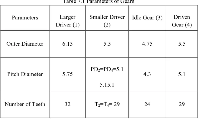
[image:8.612.139.475.210.412.2]The gears which were used in this fabrication process to build sliding mesh type gear box, the below are the various parameters regarding respective gear.
Table 7.1 Parameters of Gears
Parameters Larger
Driver (1)
Smaller Driver (2)
Idle Gear (3) Driven
Gear (4)
Outer Diameter 6.15 5.5 4.75 5.5
Pitch Diameter 5.75 PD2=PD4=5.1
5.15.1
4.3 5.1
Number of Teeth 32 T2=T4= 29 24 29
Numbering of these gears for the calculation purpose, On the basis of Driven gear (4) the remaining three gears are selected and they are,
A. Larger driver gear – it is denoted as gear 1.
B. Smaller driver gear – it is denoted as gear 2.
C. Idle gear – it is denoted as gear 3.
By this one can able to notice that the dimensions of driven gear (4) and the smaller driver gear (2) are same, however as per the selection of gears with respective driven gear (4) the dimensions of the driver (2) must and should have to meet the dimensions of driven gear (4) to achieve the velocity ratio 1 for a forward motion of the vehicle.
VIII. ADVANTAGES
A. It improves the safety.
B. It is more comfortable to the physically disabled person.
C. It gives more confident to handicapped people to drive the vehicle.
D. Easy to U turn the vehicle.
E. Easy to reverse the vehicle.
F. It is provide a better convenient chariot ride feel while driving in roadways to physical challengers.
IX. CONCLUSION
incredibly difficult .So through this project work; we interlink these two things and try to solve the problem as more as efficient with our knowledge. Hope that the launching of this vehicle in our Indian road ways would give a pleasurable development to physical challengers which may result in unity.
A. This sliding mesh type gear box results in reverse motion of rear shaft with velocity ratio 0.9
B. And In forward motion of rear shaft the velocity ratio is 1.
C. It is implemented in Handicapped Vehicle.
REFERENCES
[1] E.S.Esakiraj,S.Neeraj , Mohammed Mubeen Ali, “Modification Of The Two Wheeler Vehicle For Physically Challenged Persons” , International Journal of Innovative Research in Science ,Engineering and Technology, Vol.4,Issue3,March2015.
[2] D.P. Kapoor, Prof. S.R. Zaveri , Prof. Y.L. Yenarkar “Identification And Modification Of Desired Features To Improve The Performance Of Manually Operated Wheelchair” ,International Journal of Advanced Engineering Research and Studies E- ISSN2249–8974, July-2013.
[3] Tataso A. Garande,Prof. P.D. Sonawane, Prof. Dr. S.T.Chavan, Prof. G.S.Barpande , “Review Of Motorized Tricycle For The Disabled Person” , International Journal of Science and Research (IJSR), Volume 4 Issue 2, February 2015.
[4] Design data book, PSG College of Engineering, DPV printers, Coimbatore,page no 8.1-8.30.
[5] Prof. NarayanaIyengar B.R &Dr.Lingaiah K“Data designing data hand book, Vol 1 &Vol 2page no 24-36. [6] J.E Shigley“Mechanical Engineering Design” ,McGraw Hill Book Company, Second Edition, page no 98-102. [7] KirpalSingh “Automobile Engineering “ Vol 2 ,Eleventh Edition, page no 1,36,185.
[8] Juvinall R.C& Marshek K.M“ Fundamentals Of Machine Components Design “Third Edition, page no , 368-372.
[9] Doughtie V.L &Vallance A.V “Design Of Machine Elements” , McGraw Hill Book Company, Second Edition, page no 235-249. [10] R.S Khurmi” Machine Design Book”, First Edition, page no 839-850.
[11] Pro Engineer, Version 2.0, 2015.
APPENDIX
[image:9.612.177.437.332.677.2]
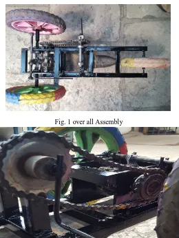
Fig. 1 over all Assembly