Technology (IJRASET)
Bank Locker Security System Using
RFID and GSM Technology
Ch.Sumalatha1, A.Viyayamanasa2, K.Ramasrujana3, I.Meghamala4, K.Lakshmi Prasanna5, K.Hema Rani6 1
Assistant Professor, 2,3,4,5,6 U.G Students, Department of Electronics and Communication Engineering, BapatlaWomen’s Engineering College, Affiliated to Acharya Nagarjuna University
Bapatla, Andhra Pradesh, India
Abstract -The main goal of this paper is to design and implement a bank locker security system based on RFID and GSM technology which can be organized in bank, secured offices and homes. In this system only authentic person can be recovered money from bank locker. We have implemented a bank locker security system based on RFID and GSM technology containing door locking system using RFID and GSM which can activate, authenticate, and validate the user and unlock the door in real time for bank locker secure access. The main advantage of using passive RFID and GSM is more secure than other systems. This system consists of microcontroller AT89C52, RFID reader, GSM modem, keyboard, and LCD, in this system The RFID reader reads the id number from passive tag and send to the microcontroller, if the id number is valid then the person has an access to open the locker.
Keywords: GSM, RFID, locking system, Keyboard, Microcontroller, LCD display
I. INTRODUCTION
In this present age, safety has becomes an essential issue for most of the people especially in the rural and urban areas. Some people will try to cheat or steal the property which may endanger the safety of money in the bank, house, and office. To overcome the security threat, a most of people will install bunch of locks or alarm system. There are many types of alarm systems available in the market which utilizes different types of sensor. The sensor can detect different types of changes occur in the surrounding and the changes will be processed to be given out a alert according to the pre-set value. By the same time this system may not be good for all the time. In this paper we have implemented safety of the money in the bank locker, house, and office (treasury) by using RFID and GSM technology which will be more secure than other systems. Radio-frequency identification (RFID) based access-control system allows only authorized persons to open the bank locker with GSM technology. Basically, an RFID system consists of an antenna or coil, a transceiver (with decoder) and a transponder (RF tag) electronically programmed with unique information. There are many different types of RFID systems in the market. These are categorized on the basis of their frequency ranges. Some of the most commonly used RFID kits are low-frequency (30-500 kHz), mid-frequency (900 kHz-1500MHz) and high-frequency (2.4-2.5GHz)[1]. The passive tags are lighter and less expensive than the active tags [2]. Global system for mobile communication (GSM) is a globally accepted standard for digital cellular communication. GSM is a common European mobile telephone standard for a mobile cellular radio system operating at 900 MHz In the current work, SIM300 GSM module is used. The SIM300 module is a Triband GSM/GPRS solution in a compact plug in module featuring an industry-standard interface. It delivers voice, data and fax in a small form factor with low power consumption. [3].in this paper we have designed and implemented a bank locker security system based on RFID and GSM technology. In this system only authentic person can be recovered money from bank locker.
II. EXISTING METHOD
Manual locking system is the one of the existing methods which is widely used by the banking system. It is insecure when the key was lost and manual interference. One more conventional method is digital locking system it is also insecure if any one hacks the password.
III. PROPOSED METHOD
Technology (IJRASET)
buzzer starts ringing and sends an SMS to the manager. This method is simple and more secure than other system.
IV. BLOCK DIAGRAM
The block diagram of Bank locker system based on RFID and GSM technology is shown in the figure5.1. It comprises the power supply section, keyboard, RFID Reader, AT89C51 microcontroller, MAX232driver, relay driver and GSM modem, LCD. The GSM board has a valid SIM card with sufficient recharge amount to make outgoing calls. The circuit is powered by regulated +5v dc. The RFID cards will be read by using RFID card reader antenna and this information will be given to micro controller by using max 232which is used to convert all RS232 logic levels to TTL logic levels. Messaging will be done by using GSM MODEM and the data will be displayed in LCD. The buzzer and buzzer driver will be connected to micro controller and motor and motor driver are provided to bank locker.
Fig:4.1. Block diagram of bank locker security system
V. CIRCUIT DESCRIPTION.
A. Circuit Diagram
Fig: 5.1.circuit Diagram
1) Working: In this we are using the 230-12v step down transformer it is down converted to 16.8v which is root 2times of the initial voltage. This voltage is applied to the full wave rectifier, it contains two diodes(D1N4007) which forms an AC signal. It is applied to the filter capacitor which converts ac to pulsating dc. Then it is applied to 7805 voltage regulator which maintains 5v constant voltage. If any ripples are present they are cleared by 100pf capacitor. When an RFID card is placed on an RFID antenna using
VC C VC C VCC VCC VCC VCC VC C VCC VCC VCC +12v 1 2 2 3 4 5 6 7 8 9 1 11 12 13 14 15 16 10 I I I I I I I I CLK OE I /O I /O O O O I RL? 3 5 4 1 2 Q? BC547 A -+ MG5 MOTOR SERVO 1 2 A -+ MG5
MOTOR SER VO
1
2
R S232 Connector
1A 2A 3A MAX232 1 3 4 5 1 6 1 5 2 6 12 9 11 10 13 8 14 7 C1+ C1-C2+ C2-V C C G N D V+ V-R1OUT R2OUT T1I N T2IN R1IN R2I N T1OUT T2OUT + 10/16 U ? AT89C52/FP 9 1 9 1 8 20 29 30 31 40 1 2 3 4 5 6 7 8 21 22 23 24 25 26 27 28 10 11 12 13 14 15 16 17 38 39 37 36 35 34 33 32 RST X T A L 2 X T A L 1 GND PSEN ALE/ PROG EA/VPP VCC P1.0 P1.1 P1.2 P1.3 P1.4 P1.5 P1.6 P1.7 P2. 0/A8 P2. 1/A9 P2.2/A10 P2.3/A11 P2.4/A12 P2.5/A13 P2.6/A14 P2.7/A15 P3.0/ RXD P3.1/ TXD P3.2/ IN T0 P3.3/ IN T1 P3.4/ T0 P3.5/ T1 P3.6/ WR P3.7/ RD P0.0/AD0 P0.1/AD1 P0.2/AD2 P0.3/AD3 P0.4/AD4 P0.5/AD5 P0.6/AD6 P0.7/AD7 + 10/16 + C? 10/ 16 R? 8.2K +
10/ 16 Y ?
11.0592
103 SIP
1
2 345 6789
C ? 33pf 103 SIP R N? 1 2 3 4 5 6 7 8 9 C? 33pf T1 TRANSFORMER 1 5 6 4 8 1N4001 1 2 1N4001
1 2 + C 1
2200uF/ 25V + 10/16 +C2 470uF/16V 7805 1 3 2
VIN VOU T
G N D Q20 BC547 LCD 1A 2A 3A 4A 5A 6A 7A 8A 9A 10A 11A 12A 13A 14A
12 V
Technology (IJRASET)
displayed on lcd and motor driver drives the motor to open the gate. If the data is invalid the motor driver rotates in the opposite direction, which means closing of gates with in provided time delay. The data is sent to GSM modem through MAX232 interface. RS232 provides serial interface between GSM and MAX232. Crystal oscillator used here is made of quartz material to provide sustained oscillations; it operates at 11.052MHz frequency. The reset logic is used to clear the previous data present in the microcontroller.
VI. HARDWARE ASSEMBLING AND TESTING
First step, we need to make single side PCB layout of the Bank locker system based on RFID and GSM technology for testing the circuit, proceed as follow
After assembling all the components on the PCB ,connect TX and RX pins of the GSM modem to pins 13 and 14 of MAX 232 and RFID Reader, respectively and insert a valid SIM in the card holder of the GSM modem.
Connect ground pins of the GSM modem and RFID to the ground rail of the circuit. This projects are implemented and tested successfully by us.
[image:4.612.202.414.247.398.2]This system is very useful for bank locker, office, homes to keep the money safely
Fig: 6.1. Hardware implementation
[image:4.612.94.513.442.684.2]VII. RESULTS
Fig :7.1 Reading RFID card by using RFID reader
Fig :7.2 Displaying the authorized person name
Technology (IJRASET)
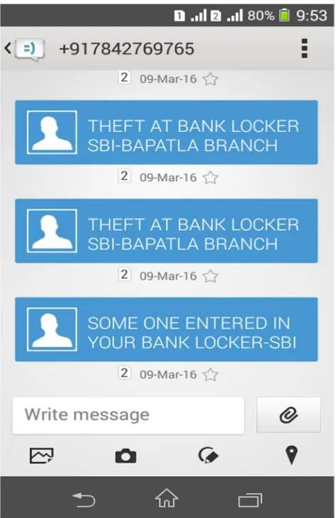
Fig :7.4 Sending SMS to bank manager using GSM modem
Fig :7.5Messages To Bank Manager When Unauthorized Entered Into Bank
VIII. CONCLUSION
Implemented a Bank locker security system using passive RFID and GSM. It is a low cost, low in power conception, compact in size and standalone system. The microcontroller sends sms to the manager for un-authorized entry and rings if anybody tries to break the based locker. This paper, is planned to a develop security system based on 3G camera for visual identification of the person.
REFERENCES
[1] Parvathy A, VenkataRohit Raj, Venumadhav, Manikanta, “RFID Based Exam Hall Maintenance System’’, IJCA Special Issue on “Artificial Intelligence Techniques Novel Approaches & Practical Applications” AIT, 2011
[2] Gyanendra K Verma, PawanTripathi, “A Digital Security System with Door Lock System Using RFID Technology”, International Journal of Computer Applications (IJCA) (0975 – 8887), Volume 5– No.11, August 2010.
Technology (IJRASET)
Technology, 2009, 21-23 Dec. 2009, Dhaka, Bangladesh.
[5] MohdHelmyA bdWahab, SitiZarinaMohdMuji, Fazliza Md. Nazir. “Integrated Billing System through GSM Network”. In Proceeding of 3rd International Conference on Robotics, Vision, Information and Signal Processing 2007 (ROVISP2007), Penang, 28 – 30 November 2007.
[6] MohdHelmyA bdWhab, Azhar Ismail, Ayob Johari and Herdawatie Abdul Kadir. “SMS-Based Electrical Meter Reading”. In Proceeding of International Conference on Rural Information and Communication Technology 2009(r-ICT),17-18 June 2009, Bandung,Indonesia.
[7] Malik Sikindar Hayat Khiyal, Aihab Khan, and Erum Shehzadi.” Sms Based Wireless Home Appliances Control System (HACS) for Automating Appliances and Security”,Issues in Informing Science and Information Technolog.Vol.9.pp.887-894.2009.
[8] Al-Ali, A.R. Rousan, M.A. Mohandes, M. “GSM-Based Wireless Home Appliances Monitoring & Control System”, Proceedings of International Conference on Information and Communication Technologies: From Theory to Applications, pp 237-238, 2004.
[9] Md. Wasi-ur-Rahman, Mohammad Tanvir Rahman,Tareq Hasan Khan and S.M. Lutful Kabir,“Design of an Intelligent SMS based Remote Metering System”, Proceedings of the IEEE International Conference on Information and Automation, 2009, pp. 1040-1043.
[10] Carelin Felix and I. Jacob Raglend, “Home Automation Using GSM”, Proceedings of 2011 International Conference on Signal Processing, Communication, Computing and Networking Technologies, pp. 15-19, 2011.
[11] Ahmad A.W., Jan N., Iqbal S. and Lee C., “ Implementation of ZigBee-GSM based home security monitoring and remote control system”, IEEE 54th International Midwest Symposium on Circuits and Systems (MWSCAS), 2011, pp. 1-4.