©IJRASET 2015: All Rights are Reserved
371
Numerical Investigation of Velocity and Pressure
Fluctuations in the Wake of a Circular Cylinder
Due To Transient Laminar Flow
Nidhul K
PG Student, Government College of Engineering Thrissur
Abstract: 2D incompressible and transient flow around a circular cylinder has been carried out numerically by using CFD fluent. The wake is generated by a uniform laminar flow of Reynolds number (Re) 150 based on the characteristic length of the cylinder, D. Flow has been studied using the Navier-Stokes and Continuity equations as governing equations with FVM employing pressure based solver and PISO scheme. A computational grid independence study has been done to obtain a grid resolution which predicts the results without any discrepancies and to optimise the computational resource used. Flow parameters such as drag coefficient, Strouhal number, velocity contours, static pressure contours and vorticity contours are calculated in this work and are in good agreement with other numerical and experimental results.The pressure distribution in the near wake region and around the circular cylinder surface is also investigated which predicts the flow separation point. The results are presented in the form of coefficient of pressure Vs Domain length/D and Coefficient of pressure along the cylinder wall.
Keywords: Circular Cylinder, Reynolds number, wake, grid independence, flow separation point, Coefficient of pressure, Drag coefficient, Strouhal number.
1. INTRODUCTION
Aerodynamics and hydrodynamics of flow around bluff bodies has attracted a great deal of attention in the literature because of its practical significance in engineering e.g., Tall buildings, monuments, and towers are permanently exposed to wind and flow of water around heat exchange tubes and immersed structures and pipes. Bluff bodies are structures with shapes that significantly disturb the flow around them, as opposed to flow around a streamlined body. A bluff body is one in which the length in the flow direction is close to or equal to the length perpendicular to the flow direction. Examples of bluff bodies include circular cylinders, square cylinders and rectangular cylinders.
Flow around a bluff body creates a large region of separated flow and a massive unsteady wake region in the downstream when compared to a streamlined body. Due to the adverse pressure gradient in the flow direction, flow separates and flow reversal occurs which creates rotational lump of fluid masses known as eddies. Eddies formed are detached periodically from either side of structure, known as vortex shedding, generates velocity fluctuations in the wake region. Alternate shedding of vortices also induces a periodic oscillatory force in the transverse direction, known as the lift force. When the natural frequency of structure is close to the shedding frequency of the vortices, the phenomenon of resonance occurs. In recent decades many researches on the flow around cylinders with variety of geometries have been done. In each of these studies, according to researchers' point of view, flow around the cylinders has been investigated from a certain perspective including pressure distribution, force coefficients, vortex shedding, flow patterns and Strouhal number. Most of these researches have been carried out through numerical methods or wind tunnel experiments.
Inoue et.al [1] constructed a non-uniform mesh but divided the computational domain into three regions, each with a different grid ratio. Mohamed Sukri Mat Ali et.al [2] numerically investigated the sensitivity of the computed flow field to flow parameters for a flow with Reynolds number 150.They constructed computational meshes based on reasonable estimates of cell size and grid stretching ratios. Sumer et.al [3] investigated and reported that the flow field over the circular cylinder is symmetric at low values of Reynolds number. As the Reynolds number increases, flow begins to separate behind the cylinder causing vortex shedding which is an unsteady phenomenon. . At a very low Reynolds number Re≤1, the flow around a circular cylinder
©IJRASET 2015: All Rights are Reserved
372
external excitation. . Bai and Li [7] studied hydrodynamic unsteady flow characteristics around a circular cylinder numerically. The pressure distribution, drag and lift coefficient and Strouhal number at Re=200 have been investigated in this 2D simulation. Gera et al. [7] studied two dimensional transient flow around a square cylinder with Reynolds number varying from 50 to 250 by employing finite element method.
In this paper, fluctuations in velocity and pressure around the cylinder and in the wake region is studied and flow parameters have been calculated at Re=150.
II. NUMERICAL SIMULATION PROCEDURE
A. Flow field formulation
The governing equations on the flow field are the continuity and momentum equations (Navier–Stokes equations), which can be written as follows:
Where ρ is the fluid density, µ is the fluid viscosity, V is the velocity vector of the flow field, p is the pressure, and u and v are the velocity components in the x- and y-directions, respectively.
Bx and By are also the body forces per unit volume, which are negligible in the present study. The fluid is assumed to be incompressible, and its properties has been taken as ρ=1.225 kg/m3 and µ=1.7894×10⁻⁵ kg/m s.
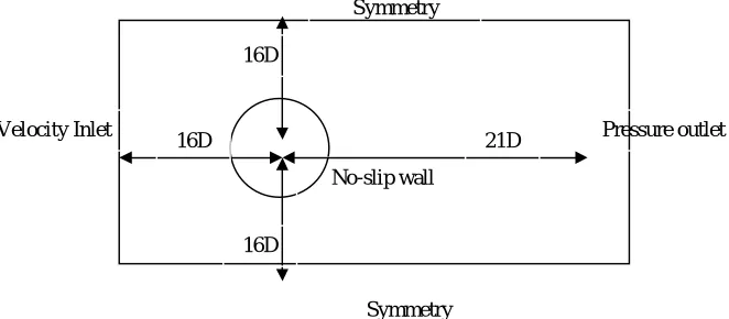
[image:3.612.117.448.405.550.2]The governing equations have been applied in the computational domain of the physical model as shown in fig.1. A rectangular flow domain is employed for study of flow over circular cylinder of diameter, D.
Figure 1:Computational flow domain for flow past a circular cylinder
B. Discretization method
The governing equations have been discretized using the finite-volume method on a fixed Cartesian-staggered grid with non-uniform grid spacing. The grids in the region of the cylinder boundaries are sufficiently fine in order to achieve the reasonable accuracy. The temporal discretization has been done in conformity with the fully implicit scheme. For the spatial discretization, the hybrid scheme has been employed. PISO (Pressure-implicit with splitting of operators) procedure was applied to calculate the flow field variables.
C. Grid influence
Various numerical studies have been conducted and it’s observed that the result comparisons show deviations from accurate value. One of the reasons for these discrepancies is the difference in the construction of the mesh. Generally, the accuracy of a numerical solution increases as the number of cells increases. But employing a larger number of cells requires more computer hardware resource and computing time. So grid independence study has been done so that the grid chosen for simulation
Velocity Inlet Pressure outlet Symmetry
Symmetry No-slip wall
16D 21D
16D
©IJRASET 2015: All Rights are Reserved
373
provides accurate results and also to optimise the computational resource available. Grid spacing was gradually increased from the cylinder surface towards the outer boundaries in order to avoid sudden distortion and skewness, and to provide a sufficiently clustered mesh near the cylinder wall where the flow gradients are large and to capture flow regime within the boundary layer. Grid independency was achieved in this study according to the procedure outlined by Yunus A. cengel and John M. Cimbala [9]. Several meshes, with increasing refinement, were tested to ensure that the solution was independent of the mesh. These meshes and the drag coefficient (CD) predictions are reported in Table 1 at Re=40. It is observed that initially with 27300 cells, the value
[image:4.612.173.441.545.708.2]of coefficient of drag is overpreicted. Whereas the value does not vary for mesh finer than 81952 cells. TABLE 1
Effect of cell density on drag coefficient for a circular cylinder at Re = 40
No. of cells CD
27300 1.560 39312 1.562 56560 1.563 81952 1.564 116392 1.564
IV. RESULTS AND DISCUSSION
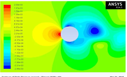
A. Pressure fluctuations
Pressure distribution is an important parameter in the study of flow around a circular cylinder. At stagnation point, located at midpoint of curve AB, flow comes to complete stop and pressure at that point thus reaches a maximum value, known as the stagnation pressure. Predicted pressure coefficient is slightly greater than 1. The distance between the inlet boundary and the cylinder is thought to be the cause of the discrepancy or may be due to the fact that cylinder is too near to the inlet boundary resulting in the built up of the flow at the stagnation point of the windward side. Flow comes to rest (v=0) at mid-point of curve AB and pressure thus reaches maximum value (By Bernoulli’s theorem) as shown in fig.2 and fig.3.
In fluid flow analysis over circular cylinder, flow separates due to adverse pressure gradient and creates eddies behind the cylinder i.e. in the wake region. Eddies are alternatively shed from top and bottom of the body which causes fluctuation in pressure in the wake region as shown in fig.4.
©IJRASET 2015: All Rights are Reserved
374
[image:5.612.171.442.267.413.2]Figure 3: Cp variation along the surface (curve AB) of the circular cylinder
Figure 4: Cp variation along the flow domain
B. Velocity fluctuations
At stagnation point, flow velocity becomes zero because entire kinetic energy of fluid is converted into pressure energy. As flow moves over the surface of the cylinder, due to no-slip condition the fluid layer in direct contact with the solid surface ceases to flow as shown in fig.5 and fig.6. Due to adverse pressure gradient and low momentum, fluid particles reverse their direction causing formation of eddies. These eddies are detached from either side of the cylinder periodically. This is known as Vortex-shedding as shown in fig.7.
Figure 5: X-Velocity contour A B
Along the cylinder surface Cp
A
B
Cp
[image:5.612.166.448.507.697.2]©IJRASET 2015: All Rights are Reserved
375
Figure 6: U/Uref Vs Domain length/D
Figure 7: Vorticity magnitude contour
Due to alternate shedding of vortices, a transverse force acts on the cylinder and in turn sets it in vibration. The Coefficient of drag is obtained as 1.321 and obtained Strouhal number is 0.186.
V. CONCLUSION
In this paper, flow behind around a circular cylinder has been numerically simulated via FLUENT software. Flow parameters such as drag coefficient, Strouhal number, pressure and velocity contours are investigated in this paper. Strouhal number and drag coefficient for circular cylinder at Re=150 are 0.186 and 1.321 respectively. Pressure variation in the wake region is due to the formation of eddies, which are shed periodically causing a transverse vibration whose frequency is given by Strouhal number.
REFERENCES
[1] Inoue, Iwakam and Hatakeyama, “Aeolian tones radiated from flow past two square cylinders in a side-by-side arrangement.” Physics of Fluids,(2006) 18(4), 046104.
[2] Ali, M.S.M., Doolan, C.J., Wheatley, V., “Grid convergence study for a two dimensional simulation of flow around a square cylinder at a low Reynolds number”, In: Seventh International Conference on CFD in The Minerals and Process Industries.(2009) CSIRO, Melbourne, Australia.
[3] D. Sumner, J. L. Heseltine and O. J. P. Dansereau, “Wake structure of a finite circular cylinder of small aspect ratio”, Experiments in Fluids, November 2004, Volume 37, Issue 5, pp 720-730.
[4] Tritton D. J, 1987, Physical fluid dynamics, Oxford University Press, Oxford
[5] Kovasznay, L.S.G., “Hot-wire investigation of the wake behind cylinders at low Reynolds number”, Proc. Roy. Soc. A (1949) 198, 174.190. [6] Roshko, A., “On the development of turbulent wakes from vortex streets.” National Advisory Committee for Aeronautics, (1954) Report 1191.
[7] Hua Bai, Jiawu Li, Numerical simulation of flow over a circular cylinder at low Reynolds number, Advanced Material Research Vols 255-260, 2011, pp 942-946.
[8] Gera. B, Pavan K. Sharma, Singh R. K, CFD analysis of 2D unsteady flow around a square cylinder, International Journal of Applied Engineering Research, Volume 1, No 3, 2010.
[9] Yunus A. Cengel & John M. Cimbala, “Fluid Mechanics: Fundamentals and Applications”, Published by McGraw-Hill.
[image:6.612.160.448.85.269.2]