Technology (IJRASET)
Application of Ranked Position Weighted (RPW)
Method for Assembly Line Balancing
Krantikumar B. Chavare1, Prof.Abid M. Mulla2
1
M.Tech Production,Department of Mechanical Engineering, Rajarambapu Institute of Technology, Rajaramnagar, Islampur, India.
2
Professor, Department of Mechanical Engineering, Rajarambapu Institute of Technology, Rajaramnagar, Islampur, India.
Abstract: Line balancing is an effective tool to improve the throughput of assembly line while reducing, cycle time. Line balancing is the problem of assigning operation to workstation along an assembly line, in such a way that assignment is optimal in some sense. This paper mainly focuses on improving overall efficiency of single model assembly line by reducing the, cycle time and distribution of work load at each work station by line balancing. The methodology adopted includes calculation of cycle time of process, calculating total work load on station and distribution of work load on each workstation by line balancing, in order to improve the efficiency of line. This related line is studied by time study techniques. The time is taken by stopwatch. The manual calculation also included especially in line balancing algorithm. In this paper a problem of line balancing for engine production has been discussed using ranked position weighted method.
Keywords: Assembly Line (AL), Assembly Line Balancing (ALB),Ranked position weighted method (RPW).
I. INTRODUCTION
The concept of manufacturing assembly line (AL) was first introduced by Henry Ford in the early 1900’s. It was designed to be an efficient, highly productive way of manufacturing a particular product. The basic assembly line consists of a set of workstations arranged in a linear fashion, with each station connected by a material handling device. The basic movement of material through an assembly line begins with a part being fed into the first station at a predetermined feed rate. A station is considered any point on the assembly line in which a task is performed on the part. These tasks can be performed by machinery, robots, and or human operators. Once the part enters a station, a task is then performed on the part, and the part is fed to the next operation. The time it takes to complete a task at each operation is known as the process time. The cycle time of an assembly line is predetermined by a desired production rate. This production rate is set so that the desired amount of end product is produced within a certain time period. One of the main issues concerning the development of an assembly line is how to arrange the tasks to be performed. This arrangement may be somewhat subjective, but has to be dictated by implied rules set forth by the production sequence. For the manufacturing of any item, there are some sequences of tasks that must be followed. The assembly line balancing problem (ALB) originated with the invention of the assembly line. However, during the initial years of the assembly line’s existence, only trial-and-error methods were used to balance the lines. Since then, there have been numerous methods developed to solve the different forms of the ALB. Development of assembly line and then balancing of the assembly line is having importance from the productivity point of view. As most of the small scale and medium scale industries are not following the various techniques available for line balancing or even line developing which may cause the loss of the productivity. These tasks can be performed by machinery, and or human operators. Once the part enters a station, a task is then performed on the part, and the part is fed to the next operation. The time it takes to complete a task at each operation is known as the process time. The cycle time of an assembly line is predetermined by a desired production rate. This production rate is set so that the desired amount of end product is produced within a certain time period when designing an assembly line the following restrictions must be imposed on grouping of work elements.
A. Precedence relationship.
Technology (IJRASET)
time should not be exceeding the cycle time.Christian Becker and Armin Scholl [1] have studies for the survey shows that assembly line balancing research which traditionally was focused upon simple problems (SALBP) has recently evolved towards formulating and solving generalized problems (GALBP) with different additional characteristics such as cost functions, equipment selection, paralleling, U-shaped line layout and mixed-model production.
Nils Boysen et al. [2] Analyzed for a classification scheme of assembly line balancing. This research reviews and discusses there is dire need of systematic evaluations to identify those decision concepts combining a (theoretical) problem type considered, the mathematical model derived and the (exact or heuristic) solution method applied which are best suited to solving real-world assembly line balancing problems.
Nils Boysen et al. [3] in this paper, tried to support practical configuration planning by suited optimization models. ALB has been an active field of research over more than half a century. This led to a massive body of literature covering plenty of aspects of assembly line configuration.
P. Sivasankaran and P. Shahabudeen [6] in this article an attempt is made to present a comprehensive review of literature on the assembly line balancing. The assembly line balancing problems are classified into eight types based on three parameters, viz. the number of models (single-model and multi-model), the nature of task times (deterministic and probabilistic), and the type of assembly line (straight-type and U-type). The research on the assembly line balancing problems is highly crucial for the productivity of mass production systems with the aim of maximizing the throughput rate.
II. TYPES OF SIMPLE ASSEMBLY LINE BALANCING PROBLEM (SALBP)
Simple assembly line balancing problems are classified into two types, type I and type II. In type I problems, the required production rate (i.e. cycle time), assembly tasks, tasks times, and precedence requirements is given. The objective of this is to minimize the number of workstations. A line with fewer stations results in lower labor costs and reduced space requirements. Type I problems generally occurs at the time of designing new assembly lines. To achieve the forecast demand the number of workstations should be reduced. For expansion (when demand is increased) type I problems also can be used to minimize the number of extra stations need to install. [8] In type II problems, when the number of workstations or number of employees is fixed, the objective is to minimize the cycle time. This leads to maximize the production rate. Type II balancing problems generally occurs, when the organization wants to produce the optimum number of items by using a fixed number work stations without expansion. In this type it is necessary to identify precedence, and constraints. While balancing the main line, it is necessary to consider subassembly lines. Type I problems are more common than type II. The exact algorithms available for the same become intractable when the problem size increases. While reasonable progress has been made in the development of exact or optimal approaches, considerable advances have been reported in the development of heuristic or inexact approaches to solve the single model deterministic task times problem.
Heuristic Methods of Line Balancing
A. Moodie -Young Method, B. Killbridge and Wester Heuristic, C. Hoffmans or Precedence Matrix, D. Immediate Update First Fit Method, E. Ranked Position Weighted Method (RPW)
The RPW solution represents a more efficient way to assign the work elements to station than any other methods mentioned above. In RPW method, one can assign cycle time and then calculate the work stations required for production line or vice versa. This cannot be done in any other method of line balancing. So in the existing problem of engine assembly line RPW method is used.
III. RANKED POSITIONAL WEIGHTED METHOD
Steps involved in RPW method. Step 1: Draw the precedence diagram
Step 2: For each work element, determine the positional weight. It is the total time on the longest path from the beginning of operation to the last operation of the network.
Technology (IJRASET)
Step 4: Assign the work element to a station. Choose the highest RPW element. Then, select the next one. Continue till cycle time is not violated. Follow the precedence constraints also.
Step 5: Repeat step 4 till all operations are allotted to one station.
IV. LINE BALANCING OF ENGINE ASSEMBLY USING RPW METHOD
For that purpose, authors decided to develop new assembly line with the help of Ranked Positional weight method (RPW).
After monitoring the different part of the engine which was assembly at only nine work station, it was decided to sub group the assemblies. So based on the observations total engine assembly into the 09 stations for assembly and 18 stations for sub-assemblies. The study has been carried out for building the whole assembly line and to find out the total cycle time using the RPW method. In this paper the use of RPW method has been discussed for only one sub assembly. Sub assembly has been presented over here to show the use of RPW method.
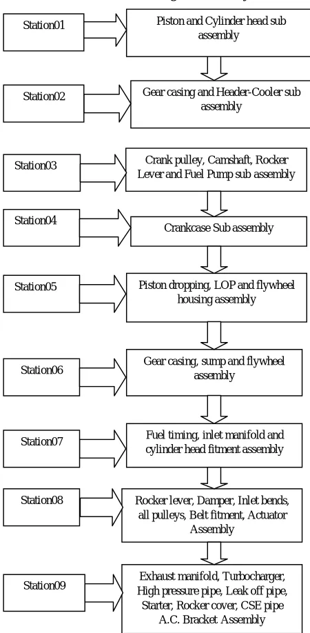
[image:4.612.44.269.241.700.2]A. Process flow chart for engine Assembly line
Fig. 1 Process flow chart Gear casing and Header-Cooler sub
assembly Station02
Crank pulley, Camshaft, Rocker Lever and Fuel Pump sub assembly Station03
Crankcase Sub assembly Station04
Piston dropping, LOP and flywheel housing assembly Station05
Gear casing, sump and flywheel assembly
Station06
Fuel timing, inlet manifold and cylinder head fitment assembly Station07
Rocker lever, Damper, Inlet bends, all pulleys, Belt fitment, Actuator
Assembly Station08
Exhaust manifold, Turbocharger, High pressure pipe, Leak off pipe,
Starter, Rocker cover, CSE pipe A.C. BracketAssembly Station09
Technology (IJRASET)
B. Tools and techniques used for data collection
Data collection tools and techniques plays crucial role as this data used for analysis. Data collection for engine line done by using following tools as follows:
1)Time study by using stop watch: Time study includes taking actual timings of engine assembly by Team Associate (TA) operations with Visual inspection.
2)Data collection by communicating with Team Associate (TA) and supervisor
C. Time and sequence of mounting subassemblies for proposed line
Total time required for the different subassemblies is 8 hours per shift. This all subassemblies are then mounted with micro time study and for that assembly time required.
Time required for mounting subassemblies 470 minutes. Hence total time for assembly one engine is 35 minutes.
Total working time = total available time X worker efficiency.
Total available time = 8.30*60 - 40 (Team associates lunch and break) = 470 minutes.
Considering 90 % worker efficiency
Total working time= 470*0.90 = 423 ̴ 420 minutes.
Cycle time (TAKT time) = Total available time / desired output = 420/12
Timerequiredfor1engine =35minutes
Monthly
Production =( )
= 25*420/35
= 300 engines. With twenty workers.
D. List and Time required for subassemblies in proposed line.
Technology (IJRASET)
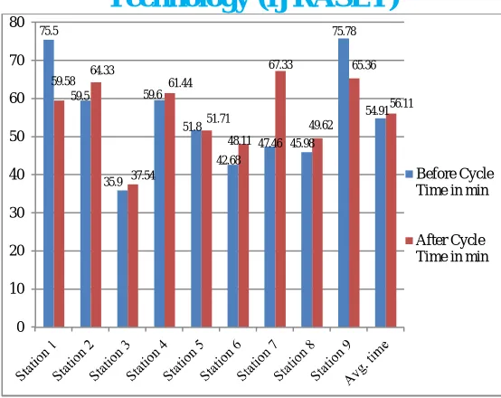
Table 2. Activity wise time study for proposed line The following figure shows comparison for cycle time in existing line and proposed line.
St. No. Activity Assembly Time
(sec.)
Total Time
(min.) TA I TA II TA III
1 Piston and Cylinder head sub
assembly 3551 59.58 26.13 33.45
2 Gear casing and Header-Cooler sub
assembly 3920 65.33 32.13 33.20
3 Crank Pulley ,Camshaft ,Rocker
Lever And Fuel Pump Sub Assembly 2205 37.15 19.26 18.28
Crankcase Sub Assembly 3687 61.44 31.03 30.41
5 Piston dropping ,LOP And bell
housing Assembly 3079 51.71 24.45 27.26
6 Gear casing, sump, oil filter and
flywheel Assembly 2879 48.11 23.08 25.03
7 Fuel timing, inlet manifold and
cylinder head fitment Assembly 4016 67.33 22.28 19.55 25.50
8
Rocker lever, Damper, Inlet bend, All pulleys, Belt fitment, Actuator Assembly
2930 49.62 26.26 23.36
9
Exhaust manifold ,Turbocharger, High pressure pipe, Leak off pipe, Starter, Rocker cover, CAC pipe and A.C.Bracket Assembly
3922 65.36 32.30 33.06
Total Task Time 30189
503.15
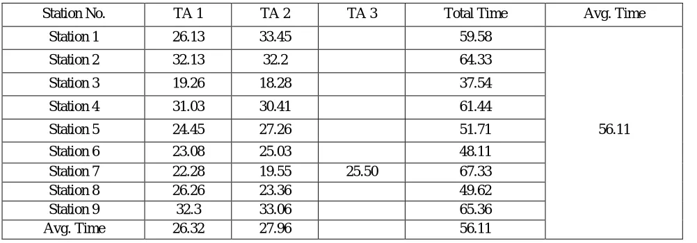
Station No. TA 1 TA 2 TA 3 Total Time Avg. Time
Station 1 26.13 33.45 59.58
Station 2 32.13 32.2 64.33
Station 3 19.26 18.28 37.54
Station 4 31.03 30.41 61.44
Station 5 24.45 27.26 51.71 56.11
Station 6 23.08 25.03 48.11
Station 7 22.28 19.55 25.50 67.33
Station 8 26.26 23.36 49.62
Station 9 32.3 33.06 65.36
Technology (IJRASET)
Fig. 2 Cycle time consumed for existing and proposed assembly line.
E. Theoretical Calculation
For final engine assembly required 18 sub assemblies which are, with help of these 18 subassemblies final engine assembly is complete. For engine assembly of Machine operators are constraints. Total twenty operators are required for complete assembly i.e., 09 on work stations and 09 for material handling. Precedence elements were identified and accordingly the precedence diagram was constructed.
Bottleneck time = 09 min Total task time = T = 69 min
Maximum production rate = 420/69 = 7 units per day Cycle time = C = 35 min
[image:7.612.51.446.360.650.2]Theoretical no of work station = N = T/C = 69/35= 1.97 = 2
Fig. 3 Precedence Diagram for Final Assembly
Table 3. Final Assembly-Sub Elements Precedence
75.5 59.5 35.9 59.6 51.8 42.68
47.46 45.98 75.78 54.91 59.58 64.33 37.54 61.44 51.71 48.11 67.33 49.62 65.36 56.11 0 10 20 30 40 50 60 70 80 Before Cycle Time in min
After Cycle Time in min
2 11 9 10 7 5 4 6 1 3 8
12 13 14
15
Technology (IJRASET)
Time (min.) Description Predecessor
1 1 Crank case moving in trolley ----
2 8 Oil priming 1
3 9 Rocker cover assembly 1,2
4 4 Leak off pipe assembly 1,3
5 1 Sensor assembly 1,4
6 6 High pressure pipe assembly 1,5
7 3 Supporting leak off pipe assembly 1,6
8 2 Fill CSI check sheet_8 and Route card_8 7
9 1 Inspection for all parts if any dent mark present or not 8
10 2 Engine un-loading 1,9
11 4 Exhaust manifold assembly 1,10
12 8 Turbocharger assembly 1,11
13 8 Diffuser assembly 1,12
14 5 CAC pipe assembly 1,13
15 2 Ac bracket assembly 1,14
16 4 Starter assembly 1,15
17 1 Inspection for all parts if any dent mark present or not 16 Applying RPW method
Step 1: Calculate RPW for each element
Time (min.) Description Predecessor
1 1 Crank case moving in trolley ----
2 8 Oil priming 1
3 9 Rocker cover assembly 1,2
4 4 Leak off pipe assembly 1,3
5 1 Sensor assembly 1,4
6 6 High pressure pipe assembly 1,5
7 3 Supporting leak off pipe assembly 1,6
8 2 Fill CSI check sheet_8 and Route card_8 7
9 1 Inspection for all parts if any dent mark present or not 8
10 2 Engine un-loading 1,9
11 4 Exhaust manifold assembly 1,10
12 8 Turbocharger assembly 1,11
13 8 Diffuser assembly 1,12
14 5 CAC pipe assembly 1,13
15 2 Ac bracket assembly 1,14
16 4 Starter assembly 1,15
17 1 Inspection for all parts if any dent mark present or not 16
Technology (IJRASET)
Element RPW Time(min.) Predecessor
1 69 1 ----
2 68 8 1
3 60 9 1,2
4 51 4 1,3
5 47 1 1,4
6 46 6 1,5
7 40 3 1,6
8 37 2 7
9 35 1 8
10 34 2 1,9
11 32 4 1,10
12 28 8 1,11
13 20 8 1,12
14 12 5 1,13
15 7 2 1,14
16 5 4 1,15
17 1 1 16
Step 3: Assign task to workstation Take cycle time as C = 35 min per unit
Workstation No. Element Time(min.) Sum of time(min.)
1 1 1
35
2 8
3 9
4 4
5 1
6 6
7 3
8 2
9 1
2 10 2
34
11 4
12 8
13 8
14 5
15 2
16 4
Technology (IJRASET)
As the calculated cycle time C = 35 min per unit every work station should have cycle time of 35 or less than 35 minutes. So on each work station assembly should be in such a way that summation of time required to process the elements should be equal or less than cycle time 35 minutes.
As shown in above tables after application of RPW method final assembly is done on nine work stations hence time required for final assembly is reduced with available manpower.
V. CONCLUSION
The main purpose of this paper is to represent use of RPW method to develop the assembly line and balancing that line. With this study it is found that RPW method is useful when the less or more data is available. Again with the help of RPW method, one can find out the way to synchronies the work stations for the work flow and sequencing. So the bottlenecking of the assemblies can be reduced. In this case study numbers of workstations have been decided and proper layout has been proposed based on RPW method. Before implementing the RPW method production rate was 210 engines per month. And after implementing the RPW method, production rate was increased by 25% with 300 engines per month.
VI. ACKNOWLEDGEMENT
I gratefully acknowledge to Prof.A.M.Mulla my esteemed guide for supporting and giving valuable guidance for research paper. And also thankful to company co-guide Mr. Akshay S.Goud and his team for co-operation and support.
REFERENCES
[1] Christian Becker and Armin Scholl, (2006) A survey on problems and methods in generalized assembly line balancing, European Journal of Operational Research 168, 694–715.
[2] Nils Boysen, Malte Fliedner and Armin Scholl, (2007) A classification of assembly line balancing problems, European Journal of Operational Research 183, 674–693.
[3] Nils Boysen, Malte Fliednera, and Armin Scholl, (2008) Assembly line balancing: Which model to use when?, Int. J. Production Economics 111, 509–528. [4] Harun Resit Yazgan , Ismail Beypinar , Semra Boran and Ceren Ocak, (2011) A new algorithm and multi-response Taguchi method to solve line balancing
problem in an automotive industry, Int J Adv Manuf Technol 57:379–392.
[5] Amardeep, T.M.Rangaswamy and Gautham j, (2013) Line Balancing Of Single Model Assembly Line, International Journal of Innovative Research in Science, Engineering and Technology,Vol. 2.
[6] P. Sivasankaran and P. Shahabudeen, (2014) Literature review of assembly line balancing problems, Int J Adv Manuf Technol 73:1665–1694.
[7] Liang Hou , Yong-ming Wu , Rong-shen Lai and Chi-TayTsai, (2014) Product family assembly line balancing based on an improved genetic algorithm, Int J Adv Manuf Technol 70:1775–1786.