Technology (IJRASET)
Design and Implementation of Advanced Wireless
Automation System Embedding PLC and HMI
Mr. Niyaj S. Nadaf1, Prof. Mrs. J. R. Gangane2, Mr. V. B. Kumbhar3
1,2
Electronics & Telecommunication Department, SIT, Lonavala.
3
Industrial Automation & Software Development, OPEL Systems, Bhosari, MIDC Pune.
Abstract— PLC is a Programmable Logic Controller used to automate the industry. There exist two types of PLC automation
wired and wireless. Compared to wire the wireless PLC automation are more robust and easy to handle. As compared to wired PLC, wireless PLC’s are expensive. To design and implement industrial as well as home automation applications with existing wired PLC we are introducing wireless PLC automation system. This project presents idea about converting the existing wired PLC into wireless PLC so that the remote field devices can be controlled without wiring, by using IEEE 802.15.4 wireless technology to PLC. The application process of automation will be controlled through HMI.
Keywords— Automation, Programmable logic controller, Human Machine Interface, ZigBee
I. INTRODUCTION
Programmable logic controllers, also called programmable controllers or PLCs, are solid-state members of the computer family, using integrated circuits instead of electromechanical devices to implement control functions. They are capable of storing instructions, such as sequencing, timing, counting, arithmetic, data manipulation, and communication, to control industrial machines and processes [12]. PLC reads the data of input devices, e.g. Keypad, sensor, switch and pulses and execute by the logic and program written in PLC memory. According to the execution of program output signals are generated are sent to output devices such as Motor, Switch, Valve etc. for automation implementation.
ZigBee falls in the category of wireless domain like GSM and RF technology. ZigBee provides the wireless communication. It means ZigBee only reduces the cost and maintenance of the wires used for connections else all the process will be same such as ZigBee will provide a particular bit on/off status to the other side due to which same message or data we can get on the other side as wire provides. Thus ZigBee replaces the connecting wires and provides a wireless communication [13].
As the wireless PLC’s use modem for transmitting signals from PLC to the process here we are using ZigBee as the communication interface which is used for transmitting and receiving the signals from the PLC to process and vice-versa. ZigBee is a wireless network developed as an open global standard to address the unique needs of low-cost and low-power wireless personal area networks (WPANs). This wireless network uses full advantage of 802.15.4 [13].
This paper is organized as follows. Section II presents Wireless and Wired network. Section III presents ZigBee and IEEE 802.15.4. In section IV Design and Implementation is presented. The conclusions are presented in section V.
II. WIRELESS AND WIRED NETWORK
Wireless technology spans a distance beyond the capabilities of typical wiring. It can provide a backup communications link in case of normal network failure, link portable or temporary workstations, wireless technology can overcome situations where normal cabling is difficult or financially impractical. In wireless technology fault finding is easy as compared to wired technology.
Technology (IJRASET)
Table 1 Comparison between wired & wireless technology
III. ZIGBEE AND IEEE 802.15.4
ZigBee is developed by ZigBee alliance, which has hundreds of member companies (Ember, Freescale, Chipcon, Invensys, Mitsubishi, CompXs, AMI Semiconductors, ENQ Semiconductors etc.) from semiconductor and software developers to original equipment manufacturers. ZigBee and 802.15.4 are not the same. ZigBee is a standard based network protocol supported solely by the ZigBee alliance that uses the transport services of the IEEE 802.15.4 network specification. ZigBee alliance is responsible for ZigBee standard and IEEE is for IEEE 802.15.4. It is like TCP/IP using IEEE 802.11b network specification. ZigBee alliance (software) defines the network, security and application layers. IEEE 802.15.4 (hardware) defines the physical and media access control layers for LR-WPAN [13].
IV. DESIGN AND IMPLEMENTATION
For testing of wireless PLC we have to implement an automation process. Here we are implementing a chemical batch process.
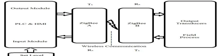
A. Block Diagram
Proposed system consists of PLC and ZigBee module. There is a wireless communication between two ZigBee modules. The single ZigBee module acts as a transceiver. Figure 1 shows block diagram of proposed system. As shown in block diagram of proposed system the any automation process in which different parameters are to be controlled and the set-point for these parameters are given by the operator/user in the HMI interface. The process is in one side and the PLC & HMI on the other side transfer and receives the signals through the ZigBee placed in between. The process is initiated by the user from the HMI interface and can be monitored and controlled by observing the flow of the process designed. PLC is placed at the control room and consists of PLC input and output modules and a ZigBee for receiving and transferring signal. Two ZigBee modules are used where wireless exchange of data takes place at the process. Then according to the control algorithm written in the PLC, the control signals from the output module of the controller (PLC & HMI) is given to ZigBee ‘A’ which acts as a transmitter module. Wireless exchange of data takes place and the signal reaches ZigBee ‘B’ which acts as a receiver module on the process side. These signals from ZigBee ‘B’ reach the process through relays on the process side and it executes output status. The input senses the corresponding signals and then it is given to ZigBee ‘B’ which now acts as a transmitter module. Wireless exchange of data takes place and the signal reaches ZigBee ‘A’ which now acts as a receiver module on the control room side. The signals from ZigBee ‘A’ fed to the controller through relays to the PLC input and this process is continues according to the execution of program.
Name Segment Length (m) Data Rate (Kbps) Nodes
Wired
Profibus
1200 93.75
32
600 182.5
200 500
DeviceNet
500 125
64
250 250
100 500
Wireless
ZigBee 100 250 260
Bluetooth 10 1000 10
Technology (IJRASET)
Fig. 1Block Diagram of proposed System
V. INPUT OUTPUT CONFIGURATION
TARANG modules are designed with low to medium transmit power and for high reliability wireless networks. The modules require minimal power and provide reliable delivery of data between devices. The interfaces provided with the module help to directly fit into many industrial applications. The modules operate within the ISM 2.4-2.4835 GHz frequency band with IEEE 802.15.4 baseband [11].
A. TMFTSoftware
TMFT Software is used to configure the TARANG ZigBee modules [11].
B. Module Programming
Step 1: Open TMFT Software.
Step 2: Connect the TARANG module to the Serial/USB Port.
Step 3: Choose the appropriate Port and serial parameters in terminal software & press query modem. Step 4: For setting I/O pins as input and output the following steps should be followed.
Step 5: Enter the command mode with ‘+++’ Response from modem should be ok.
Step 6: Enable the desired I/O pin as input with command ATIDxx. In this example first I/O line ID0 is used. For configuring it to Digital I/O input, send command as ATID02. Response from module should be ‘OK’.
Step 7: Write these parameters to memory with ‘ATGWR’ command. Step 8: Follow the same steps for configuring I/O pins to INPUT. Step 9: Exit command mode with ‘ATGEX’ command.
Note: Once I/O pins are configured to input their default status Will be logic high (3.3V).
Step 10: Enable the desired I/O pin as input with command ATIDxx. In this example first I/O line ID0 is used. For configuring it to Digital I/O input, send command as ATID40. Response from module should be ‘OK’.
Technology (IJRASET)
Fig. 2 TMFT Terminal Window
VI.AUTOMATION DESIGN
The PLC provides analog and digital series input/output that can be used to control the field devices. For the PLC to be made to control data wirelessly, a wireless interface is needed. The messages from the controller are sent to PLCs through the RF transceivers. Thus, two RF transceiver circuits have to be developed such that they are able to communicate with each other as Process Side & Control Side.
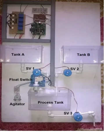
A. Process Side
[image:5.612.217.396.222.449.2]The figure 3 shows process side hardware setup for chemical batch process. The components used on process side consist of three tanks, ZigBee, Solenoid valve, Float switch and relay card. The ZigBee receives the data & control the process.
Fig. 3 Process Side Hardware Setup
B. Control Side
Technology (IJRASET)
Fig. 4 Control Side Hardware Setup
To start the automation of chemical batch process as START button is pressed by the user batch process starts. Then according to ladder program written in PLC, the control signals from output module of the controller is given to TARANG ZigBee ‘A’, which acts as a transmitter module. The first solenoid valve 1 is ON for given time in HMI screen from Tank A and then solenoid valve 2 is on from Tank B. Simultaneously if PROCESS tank becomes overflow then either solenoid valve 1 or solenoid valve 2 is off and avoid overflow condition by float switch. Then uniform mixing is done by agitator. As soon as agitator is off we get uniform mixed liquid and solenoid valve 3 is on and we get the output.
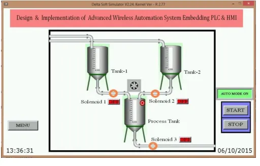
VII. HMI DESIGNS
[image:6.612.184.431.246.417.2]HMI is known as Human Machine Interface. It is not a full control system, but rather focuses on the supervisory level. As such, it is a purely hardware package that is positioned on top of hardware to which it is interfaced, in general via Programmable Logic Controllers (PLCs), or other commercial hardware modules [10].
Fig. 5 HMI Window
[image:6.612.185.441.480.643.2]Technology (IJRASET)
We achieve the task of monitoring as well as controlling the chemical Batch Process from a remote location via a PLC ladder program as well as HMI. The parameter controlled in a closed loop process is Level. For the implementation of wireless automation we have used TARANG ZigBee to transmit signals between the Control room and the Process Side.
IX.ACKNOWLEDGEMENT
The authors would like to thank reviewers of this paper and books for their valuable comments and also to the sponsored company.
REFERENCES
[1] HuiGuo, Cheng-hua Fu, Hao Wu, Shu-shuanGan, Chang-ahong Chen, “Research of wireless Communication Between PLC and Computer based on nRF2401”, International conference on Communications and Mobile Computing, Volume 3, April 2010.
[2] Xiaolong Li, Sairam Munigala, Qing-An Zeng, “Design and Implementation of a Wireless Programmable Logic Controller System”, International Conference on Electrical and Control Engineering, 2010.
[3] Kaushik Bhuiya, Kintali Anish, Dhwani Parekh, and Kilaru Laxmi Sahiti, “Low cost wireless control and monitoring using PLC and SCADA”, International Journal of Scientific an Research Publications, Volume 3, Issue 9, September 2013 1 ISSN 2250-3153.
[4] Eren, H. Curtin Univ.of Technol., “Security issues and quality of service in real time wireless PLC/SCADA process control systems” Sensors Applications Symposium, 2008. SAS 2008.IEEEBentley Hatipoglu, D.
[5] Muhammad Baqer, Mollah, Sikder Sunbeam Islam, “Towards IEEE 802.22 Based SCADA System for Future Distributed System” IEEE/OSA/IAPR International Conference on Informatics, Electronics & Vision, 2012.
[6] Giueseppe Anastasi, Marco Conti, Mario Di Francesco and Vincenzo Neri “Reliability and Energy Efficiency in Multi-hop IEEE 802.15.4/ZigBee Wireless Sensor Networks”, 2013 IEEE 11th Malaysia International Conference on Communications 26th - 28th November 2013, Kuala Lumpur, Malaysia.
[7] Mario Di Francesco, Giuseppe Anastasi, Marco Conti, Sajal K. Das, and Vincenzo Neri, "Reliability and Energy-efficiency in IEEE 802.15.4/ZigBee Sensor Networks:An Adaptive and Cross-layer Approach", IEEE journal on selected areas in communications, vol. 29, no. 8, September 2011.
[8] Francesca Cuomo, Sara Della Luna, Ugo Monaco, Tommaso Melodia, “Routing in ZigBee: Benefits from exploiting the IEEE 802.15.4 association tree”, IEEE Communications Society subject matter experts for publication in the ICC 2007 proceedings.
[9] Chumkamon, S. Tuvaphanthaphiphat, P. Keeratiwintakorn, P. “The vertical handoff between GSM and ZigBee networks for vehicular communication” Electrical Engineering/Electronics Computer Telecommunications and Information Technology (ECTI-CON), 2010 International Conference.
[10] Delta Electronics, “DELTA PLC Manual”. [11] ZigBee TMFT data sheet by Tarang.
[12] L. A. Bryan, E. A. Bryan, “Programmable Controllers Theory and Implementation Second edition” An Industrial Text Company Publication.
[13] Parneet Dhillon, Pooja Malhotra, “A Review paper on History, Current trends and Future of Zigbee (IEEE 802.15.4) Standard, International Journal of Advances in Engineering Science and Technology.
[14] D. Choi and D. Kim, “Wireless Fieldbus for networked control systems using LR-WPAN,” International Journal of Control, Automation, and Systems, vol. 6, no. 1, pp. 119-125, February 2008.