~
COLLINS
~
instruction book
Volume 1
C-System Principles of Operation
Page No. Issue Page No. Issue
Title ... Original 5-1 thru 5-23 ... Original
A ... Original 5 - 24 Blank. . . .. 0 riginal
i thru vii ... Original 5-25 ... Original
viii Blank ... Original 5-26 Blank ... Original
1-1 thru 1- 5 ... Original 6-1 thru 6-17 ... Original
1- 6 Blank. . . .. Original 6-18 Blank ... Original
2-1 thru 2-19 ... Original 6-19 ... Original
2-20 Blank ... Original 6-20 Blank ... Original
2-21 ... Original 6-21 ... Original
2-22 Blank. . . .. Original 6-22 Blank ... Original
3-1 thru 3-15 ... Original 7 -1 thru 7 -7 ... Original
3-16 Blank ... Original 7 - 8 Blank ... Original
3 -17 ... Original 7 -9 ... . . . .. Original
3-18 Blank ... Original 7-10 Blank ... Original
4-1 thru 4-13 ... Original Appendix
4-14 Blank ... Original (Paragraphs 1 thru 7) . . . .. Original
RETAIN THIS RECORD IN THE FRONT OF MANUAL.
Record of Revisions
ON RECEIPT OF REVISIONS, INSERT REVISED PAGES IN THE MANUAL, AND ENTER DATE INSERTED AND INITIALS ..ASSIGNED TO (JOB TITLE) LOCATION
REV. REVISION INSERTION
BY
REV. REVISION INSERTIONBY
NO. DATE DATE NO. DATE DATE
Page
Section 1 Introduction. . . . . . . . . . . . . . . . . . . . . . . . . . . 1-1
1.1 1.2 1.3
General ... . System Organization ... . System Operation ... .
1-1 1-1 1-3
Section 2 System Organization... 2-1
2. 1 Introduction. . . 2-1
2.2 System Hardware Organization. . . 2-1
2.2.1 Time Division Exchange System ... 2-1
2.2.2 Processor. . . .. . .. . . .. . . .. . . .. . . . .. . . 2-2
2.2.2.1 Arithmetic Logic and Control Unit
(ALCU)-8561 A-2 ... 2-2
2.2.2.2 Magnetic Core Storage. . . . .. .. . . .. . . .. . .. 2-2
2.2.2.3 Communications Service Unit. . . 2-3
2.2.2.4 Multiplex Service Unit ... 2-4
2.2.2.5 Processor Service Unit. . . . 2-5
2.2.2.6 Transfer Link ... 2-5
2.2.3 Disc Files ... 2-6
2.2.4 Magnetic Tape Units ... 2-7
2.2. 5 Peripheral Devices ... 2-7
2.2. 6 Time Division Multiplex Loop ... 2-7
2.3 System Software Organization. . . 2-7
2.3. 1 Time Division Exchange (TDX) Communication. . . 2-8
2.3. 2 Operations Control Program ... 2-8
2.3.3 Orderwire 1 Channel ... 2-9
2.3.4 Orderwire 2 Channel... ... ... 2-10
2.3.4.1 Data Collection Service. .. .. .... .. . .. . .. ... .. . 2-10
2.3.4.2 Device Acquisition and Control Service ... 2-10
2.3.4.3 Scheduler Program. . . .. . . 2-11
2.3.4.4 Load Regulation Program ... 2-11
2.3. 5 S Channel ... 2-11
2.3.5. 1 Control Program Service ... 2-12
2.3.5.2 Space Release ... 2-13
2.3.5.3 A and B Channel Queue Service ... 2-13
2.3.6 A and B Channels... 2-13
2.3.7 l\tI Channel ... 2-14
2.3.8 Common Functions. . . 2-15
2.3.8.1 Common Space Allocation and Release. . . 2-15
2.3.8.2 Disc File Storage Space Allocation and Release. . 2-15
2.3.8.3 Direct File Transfer ... 2-16
2.3.8.4 Indirect File Transfer ... '. . . . 2-16
2.3.8.5 Device Control Message Routines ... 2-17
2.3.8.7 2.3.8.8 2.3.8.9 2.3.8.10 2.3.8.11 2.3.8.12
Orderwire Translation ... . Routing and Conversion ... . Obj ect Program Mapping ... . Timer 1 Interface ... . Trapped Operation Code Interface ... . M Channel Linkage ... .
Page
2-17 2-17 2-18 2-18 2-18 2-18
Section 3 Processor Operation, Organization, and Control. • • • . • . . 3-1
3. 1 Introduction. . . 3-1
3.2 Processor Operation. . ... . .. .. . .. ... .. .. . . .. .. . . 3-1
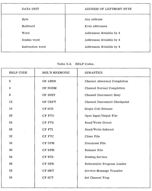
3.2. 1 Data Formats ... 3-1
3.2.2 Privileged Mode and Protected Memory. ... . . . .. . . 3-1
3.2.3 Trapped Operation Code Execution. . . 3-3
3.2.4 Interrupts ... ' ... '. . . . 3-3
3.2.4.1 Program Interrupt ... 3-4
3. 2.4. 2 Parity Interrupt ... 3-4
3. 2.4.3 Timer Interrupts ... 3-4
3. 3 Core Storage Organization. . . 3-4
3.3. 1 Processor Interfaces. . . 3-5
3. 3. 1. 1 Processor Interface Table ... 3-5
3.3. 1.2 Operations Control Table, and Operations
Sequence Table ... 3-6
3.3.1.3 Device Control Messages ... 3-6
3.3.1.4 Multiplex Status Records and the M-Queues ... 3-7
3.3.2 Channel Spaces ... 3-7
3.3.3 Common Core ... 3-8
3.4 Operations Control Program ... 3-8
3.4.1 Basic Operations Control. .. . . .. .. ... . .. .. . . ... 3-8
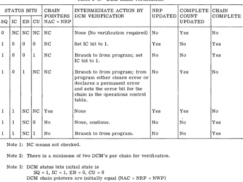
3.4.2 Device Control Message Verification ... 3-10
3.4.3 Timer Interrupts ... 3-12
3.4.3.1 Timer 0 Interrupts. . .. . . .... .. . . .. ... ... . 3-12
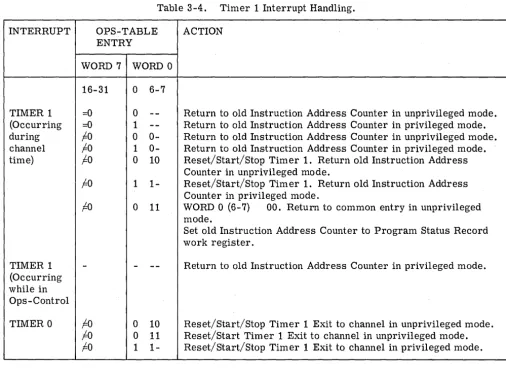
3.4.3.2 Timer 1 Interrupts. . . .. .. .. . ... ... .. .. 3-13
3.4.4 Channel Uses of Operations Control. . . 3-13
Section 4 Service lJ-lessages... 4-1
4.1 4.2 4.3 4.3.1 4.3.2 4.3.3 4.3.4 4.3.5
General
Service Message Flow ... .
Orderwire 1 Service Messages ... .
Immediate Operations ... . Service Channel Functions ... .
Orderwire 2 Channel Functions ... .
M Channel Functions ... .
A and B Channel Functions ... .
4.3.6 4.4 4.4.1 4.4.2 4.4.3
Direct Access Functions . . . . Orderwire 2 Service Messages . . . . Operator Setup . . . . Orderwire 2 Bid Message Input ... . Assign Working Channel . . . .
Page
4-11 4-11 4-11 4-11 4-11
Section 5 Time Division Exchange Loop Inputj Output Operation . . '. 5-1
5.1 5.2 5.3 5.3.1 5.3.2 5.3.3 5.3.4 5.3.5 5.3.6 5.4 5.4.1 5.4.2 5.4.3
Introduction . . . . Channel Acquisition . . . . Input/Output Operations . . . . Orderwire 1 Service Message Transaction ... . Disc File Storage Transaction ... . Tape File Storage Transaction ... . Peripheral Device Transactions ... . Orderwire 2 Service Message Transactions ... . Direct Access Transaction . . . ~
Device Control Message Execution ... . Data Channel Operation . . . . Orderwire 1 Channel Operation ... . Orderwire 2 Channel Operation ... .
5-1 5-2 5-2 5-2 5-2 5-3 5-4 5-4 5-5 5-6 5-10 5-19 5-21
Section 6 Time Division Multiplex Inputj Output. . . • . . • • • • • • • . . • . 6-1
6. 1
6.2 6.3
Introduction . . . . Environment . . . . Multiplex Service Unit/Multiplex Service Program
6-1 6-1
Communications . . . 6-3
6.4 Multiplex Service Unit/Device Communications ... '. . . . 6-8
6.4. 1 Device to Multiplex Service Unit Supervisory
Signals . . . 6-8
6.4.2 Multiplex Service Unit to Device Supervisory
Signals . . . 6-10
6.5 M Channel Subroutines . . . 6-11
6.5. 1 Subroutine Classification . . . 6-11
6.5.2 Typical Common Subroutines. . . 6-11
6.5.2.1 Open Write File (OWF) . . . 6-11
6.5.2.2 Put Segment (PTS) . . . 6-11
6.5.2.3 Close Write File (CWF) ... . . . 6-12
6.5.2.4 Open Read File (ORF) . . . 6-12
6.5.2.5 Get Segment (GTS) . . . 6-12
6.5.2.6 Release File (RLF) ... . .. . . 6-12
6.6 Time Division Multiplex Input/Output ... 6-13
6. 6. 1 Typical Input Operation . . . 6-13
6.6.1.2 6.6.1.3 6.6.2 6.6.2.1 6.6.2.2 6.6.2.3
File or Message Delivery ... . Completion . . . . Output Operations . . . . Preparation . . . . File or Message Delivery ... . Completion . . . .
Page 6-13 6-14 6-14 6-15 6-15 6-16
Section 7 File Structures .•••••. . . • • • • • • • • • • • • • • • • • • • • • • . . . • • 7 -1
7.1 7.2 7.2.1 7.2.2 7.2.3 7.2.4 7.3 7.3.1 7.3.2 7.3.3
Introduction . . . . Disc File Structure . . . . File Identifier . . . . Cell Headers . . . . Connector Cells . . . . Data Cell . . . . Tape File Structure . . . . Full Connector Structure on Disc ... . Connector Structure on Tape ... . Reels List on Disc . . . .
Appendix
1. 1.1
Orderwire 1 Service Message Formats Immediate Operations Formats
Replace Output Tape Return Initialize Ops Control
1. 1. 1 1. 1. 2
1.2 S Channel Formats
CPSR Call Program Return CP Abnormal Return AP Abnormal
Space Release
CPSR Generator Return Initial CPSR Call Redirect
1. 2.1 1. 2. 2 1. 2. 3
1. 2.4 1. 2. 5
1. 2. 6
1. 2.7 1. 2.8
1.3 Orderwire 2 Channel Formats
DACS Functions
1. 3.1 1.3.1.1 1.3.1.2 1.3.1.3 1.3.1.4 1. 3. 2 1.3.2.1 1.3.2.2 1.3.2.3
Tape Release DACS Request Replace Output Tape DACS Routing Request DCS Functions
DCS File Update from CPS DCS File Update from Program DCS Extract and Delete
1. 3. 2~ 4 DCS Code Delete
1. 3. 2. 5 DCS Code Request (Unload Allowed)
1.3.2.6 DCS File Return
1. 3.2. 7 DCS Collection Inhibit
1. 3. 2. 8 DCS Extract and Save
1. 3. 3 Scheduler Functions
1. 3. 3. 1 Scheduler Service Call
1. 3. 3. 2 Scheduler Table Generator Return
1. 3. 4 Load Regulator Functions
1. 3.4. 1 Processor Initialization
1.3.4.2 Processor Removal
1. 3.4.3 Disc Initialization
1. 3.4.4 Disc Removal
1.3.4.5 Overload
1. 3.4.6 Regulator Tables Update Return
1. 4 Multiplex Channel Formats
1. 4. 1 I/O Call 1 Service Message
1. 4. 2 I/O Call 2 Service Message
1. 4. 3 TDM Device Initialization Response
1. 5 B Channel Formats
1. 5. 1 Application Program Call
1. 5. 2 Program Call
1. 6 A Channel
1. 6. 1 Application Program Call
1. 6.2 Program Call
1. 7 Direct Access Message Format
2. Device Control Message DCM (DCM) Format
3. Operations Control Table Format
4. Processor Interface Table Format
5. Channel Save Area Format
6. Processor Status Record
Figure 1-1 1-2 2-1 2-2 2-3 2-4 2-5 3-1 3-2 3-3 4-1 5-1 5-2 5-3 5-4 5-5 5-6 5-7 5-8 5-9 5-10 5-11 5-12 6-1 6-2 6-3 7-1 7-2 7-3 7-4
System Organization ... . System Operation ... . 8561A-2 Arithmetic Logic and Control Unit ... . Communications Service Unit ... . Processor Service Unit, Controls and Indicators ... . Typical C-System Computer Center ... . System Software ... . NRP, NAC, and NWP Relationships ... . Core Storage Organization ... . Operations Control Program ... . Service Message Flow ... . File Transfer Packets ... . Direct Access Mechanism DCM's and DCW' s to
Write a Record ... . Direct Access Mechanism DCM's and DCW's to
Read a Record ... . TDX I/O Hardware Software Interface Diagram ... . Circular Linked List ... . DCM Pointers ... . DCM Header ... . DCM Operations Code Field ... . Device Control Message ... . Data Control Word Lists ... . Operations Control Table Entry and Processor
Interface Table Entry ... . Input/Output Operation ... . Working Channel ... . Multiplex Status Record Format ... . TDM Hardware/Software Interface ... . Multiple Level of Intermediate Level Connector
Cells ... .
Connector Cell Structure on Tape ... \ ... .
Basic File Structure ... . Multiple Reel Tape File Structure ... .
Table
3-1 3-2 3-3 3-4 4-1 6-1
6-2
6-3
Alignment Restrictions . . . . BRLP Codes . . . . DCM Chain Verification . . . . Timer 1 Interrupt Handling . . . . Service Messages . . . . Device to Multiplex Service Unit Supervisory
Signals Summary . . . . Multiplex Service Unit to Device Supervisory
Signals Summary . . . . MSU Operation . . . .
Page
3-2 3-2 3-11 3-14 4-4
6-9
section
I
introduction
1.1 GENERAL
The C-System is a flexible, expandable hardware system supported by modular software. Time division communication techniques enable single processor installations having limited input/output capacity to be expanded easily into large distributed networks of interconnected processors and peripheral devices. The modular operating software system complements this flexibility and permits the execution of many independent tasks on either amultiprogrammed basis by a single processor or on a multiprocessing basis when more than one processor is installed. The flexibility of both software and hardware allows easy C-System adaptation to a wide range of user requirements. This manual contains a detail explanation of the principles of operation for the C-System center.
1.2 SYSTEM OHGANIZATION
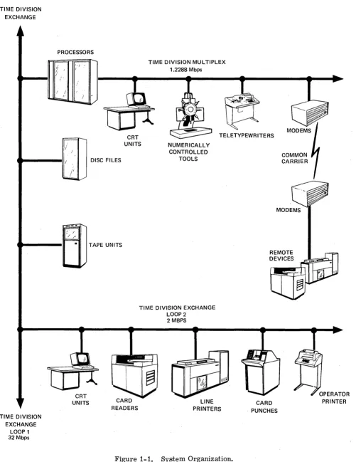
A typical C-System center (figure 1-1) consists of a number of processors, storage units, and peripheral devices interconnected by a high-speed communications facility called the time division exchange. The time division exchange is a switched communications network that allows all processors to have access to all storage facilities and peripheral devices in the center. Communication with devices that require continuous processor service is provided by a time division multiplex facility.
The time division exchange, which operates at 32 million bits per second, uses time division techniques to match its input/output data rate (2, 4, or 8 million bits per second) to that of the peripheral devices. The peripheral devices that operate at high speeds, such as disc files and magnetic tape units, are connected along a coaxial cable loop on the main exchange called loop 10 The slower-speed peripherals (such as cathode-ray-tube displays, line printers, and card readers) are connected by a second loop of coaxial cable called loop 2. This subloop provides the slower data rates (250 to 7.8 thousand bits per second) by subdividing the 2-Mbps data rate from the main exchange. Thus, the data rate from the time division exchange can be tailored to the speeds of the peripheral devices and all devices except disc files can be reassigned dynamically during system operation.
The time division multiplex communications facility connects low- and medium-speed devices directly to a processor and provides for intercenter communications. The multiplex facility operates at 1.2288 million bits per second and uses multiplexing techniques so that it can handle many peripheral devices having various data transfer rates (from 4800 to 153,600 bits per second). Each time division multiplex channel can be used to control teletypewriters, numerically controlled machines, cathode-ray-tube displays, process facilities, and other types of terminal devices.
TIME DIVISION EXCHANGE
TIME DIVISION EXCHANGE
LOOP 1 32 Mbps
PROCESSORS
"~I /
i '
;'
/
/.'
TIME DIVISION MULTIPLEX 1.2288 Mbps
CRT UNITS
TELETYPEWRITERS
DISC FILES
TAPE UNITS
CRT
UNITS CARD
READERS
NUMERICALL Y CONTROLLED
TOOLS
TIME DIVISION EXCHANGE LOOP 2
2 MBPS
LINE PRINTERS
Figure 1-1. System Organization.
MODEMS
REMOTE DEVICES
CARD . PUNCHES
[image:12.613.39.540.78.727.2]of peripheral devices to programs. The remaining processor channel (designated M channel) is used to service the time division multiplex faCility.
The programming procedures employed in the C-System involve partitioning the overall activity into separate, well defined, and manageable tasks. Once the task list has been sequenced, the input require-ments and the desired outputs are specified for each task. Together, these steps define a logical order of work and form a directed action network. Within the C-System, this logical order of work to be performed is specified by a control program. The control program directs activity within the system at the program calling level. Each task to be performed is specified by an instruction within the control program and may be dispatched to any suitable facility for execution.
As a result, the C-System operating structure allows completely automatic job execution of complex applied systems in a regulated multiprocessor environment. Messages are exchanged between processors and devices for directing work, reporting results, updating job status records and initiating new work. The result is a completely controlled processing environment.
1.3 SYSTEM () PERATION
The C-System software controls the distribution of tasks, provides the service necessary for program execution, and manages all output files. The system software implementation is based on a control program structure that allows input directed control. Control programs define the structural relationships among interrelated subtasks of an overall applied system. A control program consists of Program Control Instructions (PCl) as illustrated at the top of figure 1-2. The nodes represent program control instructions; the interconnecting lines show the required sequence of execution and indicate the outputs of program control instructions that become inputs to other program control instructions.
Each program control instruction contains information which identifies all data files necessary to execute the corresponding program, the location of the program, and other program control instructions that will require files created by execution of this program control instruction. The description and status of the control program is maintained in a control program status record. Each control program is executed by the processor that maintains the control program status record for the control program. Control prog'rams may be initiated externally or on a scheduled basis by a system scheduler. In addition to referenCing application programs to be executed, program control instructions may reference other control programs resulting in a nested control program structure.
Every processor in a C-System center may read information from any disc file but may only write to disc file space it has been aSSigned to manage. As shown in figure 1-2, processor 1 can read from or write to disc file 1, but it may only read from disc file 2; processor 2 can read from or write to disc file 2 but it may read only from disc file 1. The assignment of a whole disc file to a given processor has been illustrated here for SimpliCity; however, in actual practice disc file space may be segmented allowing several processors to write to one physical disc file but each processor is limited to an assigned segment.
CONTROL PROGRAM I
MASS STORAGE AND PERIPHERAL INPUT/OUTPUT
I A-CHANNEL I
I M - CHANNEL I
I S-CHANNEL I
IOWI-CHANNELI
IOW2-CHANNELI
LOAD REGULATOR
SEQU ENCE TABLE
SCHEDULER
EXTERNAL INPUT /OUTPUT
MESSAGES MASS STORAGE AND PERIPHERAL INPUT/OUTPUT
A-CHANNEL
B-CHANNEL
M-CHANNEL
S-CHANNEL
IOWI-CHANNELI
SEQUENCE TABLE
EXTERNAL INPUT /OUTPUT
CONTROL PROGRAM 2
~---~vr---J
TTY, NUMERICAL CONTROL, PROCESSOR CONTROL, INTER CENTER COMMUNICATIONS, VISUAL DISPLAY
8204 3224 4
Figure 1-2. System Operation.
V,Then a processor receives a service message to execute a program control instruction, the processor reads the control program status~ record from the calling processors disc file storage and obtains the particular program control instruction identified in the service message from the control program status record. The program identified in the program control instruction is then executed using input files identified in the program control instruction. The program creates an output file and stores the file on disc. At completion of the program, a return service message is sent to the originating processor noting completion of the program control instruction and speCifying the location of the output file. This process continues until all program control instructions in the control program status record have been executed.
proces-sors. To avoid an unbalanced distribution of work,_ a load regulator program, which resides in one of the processors, periodically samples work queues throughout the system. If an undesirable balance of work is detected, the load regulator program may send appropriate service messages to various processors altering the work dispatch tables to result in a more evenly distributed work load.
section
2
system organization
2.1 INTROJ) lJCTION
This section introduces the hardware organization and operating system software of a typical C -System multiprocessor center.
2.2 SYSTEM HARDWARE ORGANIZATION
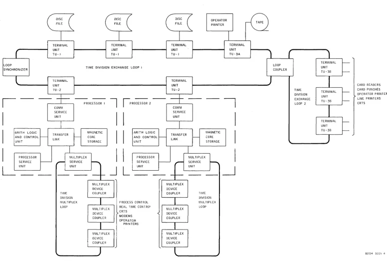
Figure 2-4 shows the basic structure of a typical C-System computer center. In general, a C-System is a multiprocessing system with several processors in a center. Processors and mass storage devices are interconnected via the Time Division Exchange (TDX) system. Connections to the exchange are made through terminal units. TU-1 terminal units connect disc files to the exchange; TU-2 terminal units connect processors to the exchange and TU-3A terminal units connect magnetic tape units and operator printers to the exchange. Subloops, designated loop 2, are connected to loop 1 by loop couplers. Card punches, card readers, line printers, CRT's, and operator printers are connected to loop 2 via TU-3B terminal units.
Two processors are shown in figure 2-4. A processor consists of an arithmetic logic and control unit, a magnetic core storage, a transfer link, a processor service unit, a multiplex service unit, and a communications service unit. The transfer link provides the interface between core storage and the other units of the processor. The communications service unit interfaces the processor to the time division exchange system. The multiplex service unit interfaces the processor to the time division multiplex system. The processor service unit is used during initial program loading and provides diagnostic and status monitoring functions during processor operation.
A Time Division Multiplex (TDM) loop may be attached to each processor for connecting low- speed devices to the processor, such as operator printers, CRT's, process control machines, and modems for remote communications. Devices are interfaced with the time division multiplex loop via a multiplex device coupler.
2.2.1 Tinw J);,';sion Exchange System
The C-System uses time division communication techniques for communication between processors, peripherals, and various input/output terminals. As shown in figure 2-4, communication between processors, disc files, tape stands, and related operating eqUipment is accomplished via time division multiplex techniques on time division exchange loops (loop 1 and loop 2). In loop 1, the loop synchronizer generates a digital pulse train at 32 Mbps. This pulse stream is used to derive sixteen 2-Mbps bit-inter-laced communication channels (every sixteenth bit is devoted to one channel)' The terminal units identify the channels by detection of a synchronization pulse generated by the loop synchronizer. Data trans-ferred on the loops contain a 32-bit word with four additional bits of supervision. It is also possible to use loop 1 channels together resulting in additional channel rates of 4 Mbps or 8 Mbps.
communication channels. The communication channels are assigned to devices such as magnetic tape units, line printers, card readers, etc., only for the duration of time these devices are being used. Party line addressing of devices can be used to allow more than one device to use the same channel.
A 2-Mbps loop 1 channel may be subdivided to provide lower-rate communication channels. The channel subdivision may be accomplished directly on loop lor, more commonly, a single 2-Mbps loop 1 channel may be used to drive another loop, designated as loop 2, which then uses the subchannels to communicate with various devices connected to loop 2. Sub channel rates of 7.8125 kbps, 31.25 kbps, 62.5 kbps, 125 kbps, and 250 kbps may be achieved. Loop 2 channels are assignable under the control of device acquisition and control service similar to loop 1 working channel assignments.
In addition to data transfers, the time division exchange system is used to transfer service messages between processors and from processors to peripherals. Orderwire 1 is used for processor-to-processor service message transfer. Orderwire 2 is used for service message transfer between processors and some peripherals. The orderwire channels are subchannels of a loop channel. Orderwire 1 operates at 125 kbps and orderwire 2 operates at 7.8125 kbps. These channels are shared and use party line. addressing to enable the device or processor to recognize a call.
2.2.2 Processor
The C-8561A-2 processor consists of an arithmetic logic and control unit, communications service unit, a multiplex service unit, from two to four magnetic core storage units, a processor service unit, and a transfer link.
2.2.2.1 Arithmetic Logic and Control Unit (ALCU).8561A.2
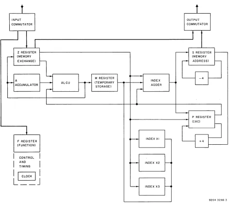
The arithmetic logic and control unit (figure 2-1) operates at 8 MHz and has a typical instruction execution time of 2.9 to 5.6 J.l.S, including memory access. A total of 72 instructions is available, 65
fixed-wire and 12 executed in a trapped mode. An optional algorithm unit allows hardware execution of all floating point instructions and fixed point multiply and divide.
The arithmetic logic and control unit (figure 2-1) uses a 32-bit accumulator called the A lator, a 32-bit accumulator called the B accumulator, or a combination of both, called the D accumu-lator. Three 18-bit index registers provide storage for address modifiers used in indexing operations.
In the arithmetic logic and control unit, the three main registers communicate with the transfer link through input and output commutators. These are the function register, F, the memory exchange register,
Z, and the memory address register, S. The F register holds the 14 bits of the instruction that include the operation code and control bits. This register interfaces with the instruction decoding control and timing circuits. The Z register, 32 bits in length, receives or transmits one word in parallel to the transfer . link. All data to or from memory passes through the Z register. The S register, 18 bits in length, transmits the address of each memory word to be accessed through the transfer link.
The P register serves as the program counter or Instruction Address Counter (lAC). This register, 18 bits in length, holds the address of the next instruction to be executed in the program. The instruction address counter increments by 4 to skip from one instruction word to the next (memory is organized with byte addressability).
The 32-bit M register serves as temporary storage for data from the other registers during the machine cycle.
2.2.2.2 Magnetic Core Storage
t
t
INPUT OUTPUT
COMMUTATOR COMMUTATOR
I
t
Z REGISTER , - - - S REGISTER
--
(MEMORY (MEMORYEXCHANGE) r--
,..
ADDRESS)-
L[J-"""-" M REGISTER ~
.-
Ar----
ALCU ~...-- (TEMPORARY INDEX ~ ACCUMULATORSTORAGE) ADDER
r--
,..
J
-
P REGISTER (lAC)r--~
LfJ=
~ INDEX XI
r--F REGISTER (FUNCTION)
I
CONTROLI
I
ANDI
~ INDEX X2 ---1TIMING
I~I
L __ J
~ INDEX X3 ~
8204 3266 3
Figure 2-1. 8561A-2 Arithmetic Logic and Control Unit.
262,144 bytes for one processor. In addition to load or unload memory cycles, the unit has the capability of performing an unload-modify-Ioad function in one memory cycle.
Each module in the memory has its own address and data buffers and it is possible for all four modules to operate concurrently. The alcu, communication service unit, processor service unit, and multiplex service unit may all request the use of the memory independently. If four units request the access of different memory modules, the entire memory can be in operation at the same time. The transfer links operate at a speed that makes this possible; together they can perform the four transfers of 32 bits in 2 }lS.
2.2.2.3 Co nUll ,wit:ations Service Unit
[image:18.612.94.566.77.495.2]CORE STORAGE
-
-
- - -
- r-- - - r- - -- - - -
- - -- - -
-I
COMM SERVICE
I
UN"I
A M S OW2 OR B
OW/ATC OWl DATA CHANNEL DATA CHANNEL DATA CHANNEL DATA CHANNEL I+----
-I
I
L - - r-- - - -
- -
- - -- - - -
- - -- - - -
~TERMINAL UNIT TU-2
B204 3264 3
Figure 2-2. Communications Service Unit.
in main core storage for use by system programs. Another data channel is used exclusively for order-wire 1 data channel transmission of service messages between processors. Three of the four remaining data channels are dedicated to the processor channels (programming channels) for communication between programs executed in the processor and peripherals connected to the time division exchange loops such as disc files, card readers, printers, etc. The sixth data channel is used by either the orderwire 2 or the
B processor channel. One processor in a center is responsible for orderwire 2 functions including assign-ment of time division exchange working channels to magnetic tape units and loop 2 devices and necessary control messages to these peripherals. In the remaining processors in the center, this channel is used to support B channel processing.
The communications service unit has direct access to core storage through the processor transfer link. Data records to files and messages for otherprocessors are read from and written to core storage directly under communications service unit control. To instruct the communications service unit, the arithmetic logic and control unit builds device control messages which are 9-word instruction packets in core which the communications service unit reads and executes. The instruction packets contain device control information and core location information for data and status. Once a device control message is built for an input/output transaction or a processor message transfer, the arithmetic logic and control unit is free to continue other work while the communications service unit executes the required information transfer.
2.2.2.4 Multiplex Service Unit
The multiplex service unit drives the serial multiplex loop at 1.2288 Mbps and inserts appropriate synchronizing pulses into the bit stream to identify 256, 4.8-kbps time slots. The time division multiplex loop provides word-interlaced channels that allow simultaneous access between a processor and the medium- or low-speed devices connected to the time division multiplex loop.
[image:19.612.48.528.77.309.2]The multiplex service unit allows a device on the time division multiplex loop to communicate with the arithmetic logic and control unit by requesting processor service. The multiplex service unit directs the transfer of data between devices and core storage through the transfer link without arithmetic logic and control unit intervention once the arithmetic logic and control unit has set up the transaction. The multiplex service unit also alleviates the arithmetic logic and control unit of the routine task of· monitoring devices on the time division multiplex loop for service requests. When a device needs processing time, an appropriate indication is placed in work queue serviced by the arithmetic logic and control unit. The indicator points to a multiplex status record corresponding to the device requiring service. The multiplex status record is used by the arithmetic logic and control unit and the multiplex service unit to transfer information. A multiplex status record is a 4-word table located in core storage. Each active multiplex status record contains sufficient information for the arithmetic logic and control unit to accomplish the task required by the device. Typical arithmetic logic and control unit tasks include the management and allocation of core storage used for time division multiplex loop data buffers, the transfer of records to and from disc files, and the execution of special device-oriented subroutines. Devices on the time division multiplex loop initiate all communication with their associated processor by transmission of the proper instructions to the multiplex service unit. When a device on the time division multiplex loop is idle, it accepts output information from the computer.
2.2.2.5 Proc,',,,,wr Service Unit
The processor service unit performs the functions of controlling initial program loading of the processor, initiating processing, and performing selected diagnostics on processor units. The processor service unit has interface connections with the communications service unit, multiplex service unit, transfer link, arithmetic logic and control unit, terminal unit, and main core storage.
The processor has three manual operating controls which are contained on the front panel of the proces-sor service unit (figure 2-3). The IPL button starts the automatic initial program load sequence, which loads programs from the time division exchange loop. During initial program load, the memory protec-tion feature i8 overridden. The Initiate (INIT) button initializes the arithmetic logic and control unit with-out loading a program. Lamps on the panel of the unit indicate that the processor is operating normally (RUN) or that it has failed (Machine Failure Monitor, MFM). An 8-bit lamp-bank indicates which cessor function has failed during an initial program load. Upon successful completion of an initial pro-gram load, these lights are under propro-gram control. The Marginal Voltage Test (MVT) button allows for marginal voltage testing.
The proces8or service unit controls certain operations of all processor units. These include enabling the arithemetic logic and control unit and communication control equipment, enabling diagnostic mode to all units, controlling marginal voltage tests, forCing memory parity errors in all memory modules, disabling protected memory, controlling interleaved memory mode, and displaying status via the 8-bit lamp-bank on the front of the processor. These functions are controlled by the processor service unit during an initial program load or initiate sequence. After a successful initial program load or initiate, these functions are under the control of software. Every time the arithmetic logic and control unit executes a reset machine failure monitor instruction, the processor service unit will set the above functions to reflect the bits in memory location X' 40. This word is referred to as the processor control word.
The processor service unit maintains a processor status word in memory location XI44. This word contains the current status of the fault alarms of all processor hardware.
2.2.2.6 TrallHj,'r /.ink
RUN
MFM
~
~
IPL
MVT
INIT
[image:21.618.72.492.77.470.2]8204 3265 2
Figure 2-3. Processor Service Unit, Controls and Indicators.
logic modules and any two of four memory modules connected to the transfer link. Up to four logic units may be connected to any of the transfer link module source ports. Also, tip to four transfer link modules may be connected in parallel by busing together the memory ports thus allowing eight source ports. If both source ports from the same transfer link attempt to access the same memory module at the same time, the transfer link resolves the conflict on a first in, first out basis. For systems employing more than one transfer link module, a weighted priority between transfer link modules is established by means of the priority interconnect between the boxes.
2.2.3 Disc Files
The second unit is a high-speed, random-access device with a storage capacity of 33.5 megabytes on 8 discs. The average head positioning time for this device is 18.4 ms with a 6 ms minimum and 30 ms maximum. The disc revolution time is 25 ms and the data transfer rate is 350,000 bytes per second.
2.2.4 M agm!lic Tape Units
The 9-channel magnetic tape unit operates with 1/2-inch magnetic tape. The unit reads in the forward and reverse tape directions and writes in the forward direction at 150 inches per second; the rewind speed is 250 inches per second. Data is stored at a density of 800 bits-per-inch per channel. Eight channels are used for data and one for parity. The data transfer rate is 120,000 bytes per second.
The 7-channel magnetic tape unit operates with 1/2-inch magnetic tape. The unit reads and writes in the forward direction at 150 inches per second; the rewind speed is 360 inches per second. Data is stored at a density of 200, 556, or 800 bits-per-inch per channel. Six channels are used for data and one for parity. The data transfer rate is 30,000, 83,000, or 120,000 bytes per second.
2.2.5 Peripllt·ral Devices
The C-System provides the following optional peripheral devices: card readers, card punches, operator printers, line printers, and CRT display and entry stations. These devices connect to time division exchange loop 2 through TU-3B terminal units.
2.2.6 Time /);I';.'Iion Multiplex Loop
The time division multiplex loop provides connection of a large number of low-speed devices to a single computer within the C-System. The loop is physically a coaxial cable which interconnects the various devices in a serial manner and terminates at the multiplex service unit. The basic data rate on the loop is 1.2288 MHz. In contrast to the time division exchange system which is bit interlaced, the time division multiplex loop operates with word interlacing with 256 words (36 bits each) in one frame resulting in a frame length of 9216 bits. Each time division address corresponds to a device channel; the channels are not reassig'nable as in the time division exchange working channels. A framing pulse generated in synchronization with the first time division address is used to identify the channel words in the loop. Data is inserted and extracted from the channels by the multiplex service unit and devices. A device may be assigned 1, 8, 16, or 32 time division addresses, providing effective channel bit rates of 4.8 kbps, 38.4 kbps, 76.8 kbps, or 153.6 kbps.
The multiplex device coupler provides a standard interface to devices on the time division multiplex loop. The multiplex device coupler performs the functions of time division address recognition, serial extraction and insertion of data into its assigned time division address channel, and logical interpretation and generation of the supervision necessary to communicate with the multiplex service unit.
The loop word format for each of the 36-bit time diviSion addresses consists of a 4-bit supervisory code field and 32-bit operand. The supervisory field contains the supervising codes for multiplex service unit to multiplex device coupler communication. The operand contains the instructions, data, parameters, etc., for the device and programs.
2.3 SYSTEM SOFTWARE ORGANIZATION
2.3.1 Time Division Exchange (TDX) Communication
Communication between the communications service unit data channels and programs running in the processor channel is by means of Device Control Messages (DCM's) which are built by system programs on each of the various channel time. Device control messages are instruction packets directing a data or message transfer; the communications service unit reads and executes the packets. As shown in figure 2-5, each processor channel has two device control message chains; a typical device control message is shown in the upper left-hand corner. There are an arbitrary but fixed number of device control messages in each chain and the entire chain is in a fixed location in core storage with each device control message having a fixed starting address. Each device control message in the chain con-tains a device control message chain pointer to the next device control message in the chain with the last pointing to the first, thus forming an endless chain. The two device control message chains for each processor channel are· serviced alternately by the corresponding communications service unit data channel, with one device control message per chain being serviced on each chain access by the commu-nications service unit.
The actual data and message transfer on the time diviSion exchange system takes place strictly under terminal unit and communications service unit control through execution of the device control message chains. The transfer does not involve the arithmetic logiC and control unit except for building the device control messages, data control wordS, device control wordS, and monitoring device control messages for transfer completion.
Data Control Words (DCW's) are appended to device control messages. Data control words contain control bits defining the nature of the data or message transfer and the core address of the data to be transferred or the area into which data is to be read. Data control words are also used to point to device command words that identify, for example, the read or write function and the address of a disc file record. A data control word can be used to identify another list of data control words not appended to the device control message but to be executed with this device control message. If such a data control word is encountered in executing a device control message, the data control word chain address is placed in the third and fourth bytes of the second word of the device control message and this address is branched to at an appropriate place in the execution of the data control word list.
The first word of the device control message contains certain control bits and the device control message chain address pointing to the next device control message in the chain. The second word con-tains the loop 1 and loop 2 time division exchange address of the device which communication is to be established and two bytes for adata control word chain address. The third word contains a from-program address, which references a program that is branched to in the event of an error and that may be given immediate control upon verification of completion of this device control message. This word also con-tains the response address for storage of device status at completion of the transfer • .The fourth word of the device control message is the first data control word to be executed in the transfer.
In addition to the device control message chains for each channel, each processor core has a set of prebuilt device control messages and data control word lists which reference certain tables in the processor core for direct access by the load regulation program via orderwire 1 service messages. In general, a pair of device control messages and data control words (one for reading and one for updating) is required for each table to which the load regulator has access.
2.3.2 Operations Control Program
is the next entry in the queue to be executed by the channel programs. The next three words in an opera-tions control table entry are device control message chain pointers for chains 1 and 2. The next- read-position pointer is the next device control message to be checked by the operations control program for completion; the next-write-position pointer is the next device control message which can be used to post an input/output request, and the Next Available Cell (NAC) identifies the next device control message to be executed by the communications service unit.
The operations control program, shown in the center of figure 2-5, is the resident software system responsible for allocation of arithmetic logic and control unit time and verification of device control message chains for completion of input/output requests. The operations control program can be entered from a given channel in one of four ways: (1) the channel may run to completion and exit to operations control (OP COMP) in which case the second bit, I, in the operations control table is set to idle and a return address saved; (2) the channel may disconnect busy (OP BUSY) awaiting an input/output comple-tion in which case I is set to not idle and the third bit, B, of the status word in the operacomple-tions control table is set to busy and a return address saved; (3) the channel may voluntarily relinquish the rest of its time when certain conditions are met in the program execution in which case I is set to not idle and B to checkpoint and a return address saved; or (4) the channel may be interrupted by the interval timer in which case I is set to not idle and B to checkpoint and all arithmetic logic and control unit registers saved in the channel program status record so that the channel may resume proceSSing the next time it gains control of the arithmetic logic and control unit. All methods of entry to the operations control program are used by the A and B channels but, under normal operating conditions, the M and S channels only use entries 3 and 4 while orderwire 1 and 2 channels only use entries 2, 3, and 4. The operations control program works with the operations sequence table which indicates the sequence in which the channels are to be given time. This sequence is arbitrary and may be any order depending on the processing task. Upon entry, the operations control program examines the sequence table for the next channel to service. The idle bit is then checked to determine the channel status. If the channel was idle, the next-read-position pointer and next-write-position pointer for the channel work queues are compared to determine if any channel work has been posted since the channel last had control. If the next-read-position pointer does not equal the next-write··next-read-position pointer in either queue, then work is available
and operations control exits to the channel. If the next-read-position pointer equals the next-write-position pOinter, no work is required and the operations control program checks the sequence table to determine the next channel to be given time. Only the A and B channels use this test since only these channels enter operations control as idle. The other channels manage their own work queues, using the next-read-position and next-write-position as appropriate.
If the channel was not idle the last time it had control, operations control proceeds to verify device control messages for completion on that channel. By monitoring the status bits in the device control messages for the particular channel, the operations control program can detect whether or not any input/ output requests have been completed. The B bit of the status word of the operations control table can then be checked to determine if the channel was awaiting a data transfer. If the channel was awaiting a data transfer and none has occurred, the channel is skipped and operations control returns to the sequence table; if at least one device control message had been completed by the communications service unit, operations control will return control to the channeL If the channel had used the voluntary checkpoint as indicated by the third bit of the operations control table status word, control is returned to the channel program regardless if an input/output has been completed. Likewise, if the channel had been interrupted by the timer, the arithmetic logic and control unit is restored to its prior condition and control retUrned to the channel.
2.3.3 Orderw; (t' I Channel
can be written. When orderwire 1 is indicated by the operations sequence table and the operations control program detects one or more completed device control messages in the orderwire 1 device control message chain, the orderwire 1 input program is given control. The orderwire 1 input program decodes the operation code of the service message. Certain service messages require immediate processor action. The orderwire 1 input program immediately initiates the appropriate routine called in the immediate service message. All other service messages are either directed to service queue 2, which is a work queue for the orderwire 2 channel, service queue 1 which is a work q\...,ue for the S channel, or Multiplex Channel Queue (MCQ) which is serviced on M channel time. For service queue 1, service queue 2, and the multiplex channel queue, a pointer indicating the location of the service message in core is placed in the queue. The orderwire 1 input program reinitializes the device control message by obtaining a new bin for a service message. The orderwire 1 input program exits to the operations control program as busy awaiting an I/O when all device control messages have been reinitialized and does not receive control again until another device control message is complete. The orderwire 1 input program uses the voluntary checkpoint entry to operations control if buffer space is not available for assignment or if the work queues are full, ensuring return of control the next time orderwire 1 is indi-cated in the sequence table.
2.3.4 Orderwire 2 Channel
Orderwire 2 channel time is used for execution of the scheduler, Data Collection Service (DCS), Device Acquisition and Control Service (DACS), and the load regulator. Requests for service for these channel programs are received from orderwire 1 service messages via service queue 2 and from service messages received via orderwire 2 used only by device acquisition control service. An orderwire 1 service message input decode program decodes the service messages from service queue 2 and posts them for various orderwire 2 channel programs. The orderwire 2 input program maintains input device control messages and service message bins for input service messages. When a message is received, the orderwire 2 input program places the message in a work queue and reinitializes the device control message for receipt of subsequent orderwire 2 service messages. Control is given to the orderwire 2 input program each time a channel program gives up control. A channel program gives up control after it performs a file service request or completes processing of a service message. The orderwire 2 allocator gives each channel, in turn, time to process provided the program is not waiting for the comple-tion of a file service request. Each time the work allocator is given control, the work allocator allows only one function to run.
2.3.4.1 Data Collection Service
Data collection service runs on orderwire 2 channel time and provides applied systems with a means of collecting, categorizing, and distributing raw input data from any point in the system. All data input to data collection service must have a preassigned data collection service code. A data collection service code is assigned by data collection service on receipt of a data collection service code request service message. All input files with the same data collection service code are maintained in a collection file. There is only one collection file per aSSigned data collection service code. The collection file is a file on disc that contains the input file identifiers for the files associated with a data collection service code. When a data collection service extract service message is received, data collection service returns via a program return service message the address of the collection file which the user may then access to obtain the location on disc or tape of the data needed.
2.3.4.2 Device Acquisition and Control Service
control of a control program status record encounters a program control instruction requiring commu-nication with a magnetic tape unit or a loop 2 device. An orderwire 1 service message is sent to device acquisition and control service to establish communication. The orderwire 1 input program directs the service message to service queue 2 where it is decoded by orderwire 1 input decode as a device acquisi-tion and control service request. Device acquisiacquisi-tion and control service processes the messages, assigns a working channel to the required device, builds an output file containing control data and device status, and identifies the working channel assigned to the device. A return service message is sent to the calling processor identifying the output file which it then accesses, obtains the working channel identification, and begins communication with the device.
In the device mode, device acquisition and control service receives an unsolicited orderwire 2 input mes-sage from a loop 2 device requesting to input data into the system. In this case, a program call service message is issued for a device acquisition and control service defined device-to-disc program which will store and forward the input data.
2.3.4.3 Sc1wt/,,/,!r Program
The main purpose of the scheduler program is to control the initialization of application program sys-tems or portions of application program syssys-tems as a function of time. Orderwire 1 scheduler call service messages are directed to the scheduler program through service queue 2 and the orderwire 2 allocator. The service message identifies the orderwire 1 time division exchange party line address of the calling processor, the time the application system is to be initiated, a priority code, and the disc file storage address of the application system control program status record. The received service messages are placed in one of four priority queues in order of activation time by a table generator program which is a nonresident program that runs on a scheduled basis on A or B channel time. Thus, received service messages are placed in a queue to be serviced later by the table generator program if their execution time is later than the next scheduled run of the table generator program; otherwise, the service message is tabled in an advanced activation cell and can be operated on by the scheduler without being filed by the table generator program. When the scheduler program is executed, the current time obtained from the absolute time clock storage location is compared to the activation time specified in the first service message in each queue. If the current time is greater than or equal to the activation time, a return service message is sent via orderwire 1 to the calling processor indicating time to activate the scheduled program.
2.3.4.4 Load 1l,'/.pLiation Program
The purpose of the load regulator program is to automatically regulate the work load in the various processors in the system. The load regulation program is executed in the orderwire 2 channel of one processor in a center and dispatches direct access service messages to the various processors in the center. The communications service unit orderwire 1 data channel hardware recognizes the service messages as direct access messages and executes the prebuilt direct access device control messages and data control word lists which reference particular parameters in core storage to be returned to the load regulator. Having sampled each processor, the load regulator program can detect any undesirable distribution of work that may exist in the various channel work queues throughout the center. If such an undesirable balance is detected, the load regulation program will dispatch additional immediate access messages to change dispatch parameters utilized by the various processors in aSSigning program control instructions for execution.
2.3.5 S ClulIlllf'/
chain, and control is returned to S channel decode rather than the operations control program. This allows other S channel programs to execute as required on remaining S channel time. S channel decode always uses the voluntary checkpoint entry of the operations control program, unless a timer interrupt forces relinquishing channel time. When S channel decode is entered from either operations control or an S channel program, it always checks its completion chain first to determine whether or not any requested input/output transactions have been completed. If they have, control is transferred to the program requesting the transfer. After the entire completion chain has been checked, service queue 1 is checked for service messages directing further work.
2.3.5.1 Control Program Service
Control Program Service (CPS) runs on S channel time, is resident in each processor in a center, and is responsible for the supervision of the execution of control programs assigned to that processor. Control programs represent the technique utilized in the C-System for implementing input-directed control for automatic and regulated execution of application system programs in a multiprocessor center. Control programs are physical lists of program control instructions each of which identifies a particular segment of the overall system for execution. The program control instruction also identifies any input files required for execution of the program and points to other program control instructions in the control program that require the execution of this program control instruction before being executed. The program control instruction identifies files which can be released after completion and also contains various control parameters required by control program service in the execution of the control program.
running on a periodic basis. The latter is implemented by sending a service message to the scheduler upon completion of a control program, directing the scheduler to return a message at a certain time automatically reinitiating the control program.
Control programs may exist in one of two states: (1) as a Control Program Status Record (CPSR) or (2) as a Control Program Status Constant (CPSC). A control program status record is generated from a control program status constant by the control program status record generator program which is a nonresident program run on the B channel of a processor in response to a control program status record generator call service message. This message may originate from another program control instruction, or it may be generated externally and entered, for example, through the time division multiplex loop. The control program status record generator program makes a copy of the control program status constant, placing certain information in the control program status constant creating the control program status record, which is then activated.
2.3.5.2 Sp(l(~(' Ildease
The space release service message routine resides in each processor in a center, ru"ns on S channel time, and releases file space referenced by a file release service message. These service messages are generated by control program service and may come from any processor in the center for release of file space managed by the particular processor receiving the service message. Control program service generates file release service messages upon completion of program control instructions; the messages reference storage files no longer needed. This routine calls upon the common function release file routine to release the file space. The orderwire 1 service message space used by the service message is then released via the common function common space release.
2.3.5.3 A (llld Jl Channel Queue Service
A and B channel queue service runs on S channel time and queues service messages directed to the A or B channel. This program is given control by S channel decode upon detection of an A or B channel service message. A and B channel queues consist of one 2048 byte cell each and are located on disc file storage. There are two queues for each channel and the queue cell addresses, read and next-write displacements from the top of each queue, are maintained in the operations control table. Because these queues are fixed length, the load regulator program periodically examines them to determine if
any of the queues are above a predetermined level. If any queue is nearing capacity, the load regulator program removes the respective channel from the load dispatch tables of all processors in the center. To ensure that loss of queue entries due to queue overflow does not occur, an overflow queue is assigned when regular queues reach a certain level. If an overflow queue is being used, the overflow bits in the channel operations control table entry are set.
2.3.6 A flnd Jl Channels
System routines that run on A and B channel time are initiated by program call service messages and are not necessarily initiated directly by a program control instruction nor do they all require completion response. These programs include the following:
a. System checkpoint
b. Device acquisition and control system library support c. Schedule table generator
d. Control program status record gen~rator program e. Data collection service table update
f. Disc drain
g. Initialization, backup and recovery h. Time division exchange message output
i. Disc zone purge
j. Load regulation
k. Time division exchange unsolicited input 1. Tape structure release and restore
2.3.7 M Channel
M channel time is used by the Multiplex Service Program (MSP) to service the requests of devices on the time division multiplex loop, such as CRT display and entry stations and teletypewriters.
The multiplex service program (figure 2-5) consists of a resident Multiplex Channel Control (MCC) program and various subroutines of the multiplex channel. When the multiplex service program is given control of the processors arithmetic logic and control unit facility from the operations control program, multiplex channel control monitors Multiplex Queue·1 (MQl), Multiplex Queue 2 (MQ2), Multiplex Channel Queue (MCQ), File Transfer Command Queue 1 (FTCQl), and File Transfer Command Queue 2 (FTCQ2) for channel activity status, invoking the proper routines to service requests as they are encountered. In the absence of any pending multiplex operations or if all outstanding operations are performed before the interval time period has elapsed, multiplex channel control relinquishes the remainder of channel time to the operation control program via the voluntary checkpoint entry (OP CKPT).
The time division multiplex loop is a serial, word-interlaced 1.2288-Mbps communication facility pro-viding 256, 4.8-kbps time slots. Communication between the multiplex service program and devices on the time division multiplex loop is accomplished via the Multiplex Service Unit (MSU) which allows service request inputs and instruction outputs as well as data movement to and from core storage independent of the arithmetic logic and control unit. This is accomplished via a table of Multiplex Status Records (MSR's). There are 256 multiplex status records in the table, one for each time division multiplex time slot with a provision for 512 for full duplex devices. Each multiplex status record (figure 2- 5) is four words in length. The first word, called the F word, is used to pass instructions to and from the device and to pass core addresses for field load and store operations. The D word is used for a data buffer when transmitting data a word at a time to or from a device. If an entire field is to be moved, the D word is not used. The R word is used in a link mode operation when two buffer areas or data bins are assigned in main core storage. In this case, the address of the first area is in the F word while the second is in the R word allowing multiplex service unit chaining from one to the other immed-iately without arithmetic logic and control unit intervention to assign a new bin. The P word is used for various control functions and as pointer to a channel status record.
multiplex queue 2. The multiplex queue 1 and multiplex queue 2 entries signal the multiplex service program to service the associated multiplex status record.
Disc file storage data transfers from M channel are handled by M channel subroutines. An input and an output queue, file transfer command queue 1 and file transfer command queue 2, are provided for posting file transfer requests. A file transfer command queue service module of the multiplex service program services these queues directing the building of device control messages as required. The use of completion chains enable the M channel to monitor its own input/output for completion and the channel does not checkpoint busy to the operations control program awaiting input/output.
Orderwire 1 service messages directed to M channel are input through the multiplex channel queue which points to the orderwire 1 service message. Such a message may, for example, direct the output of a data file on disc storage to a time division multiplex device. M channel routines may send orderwire 1 service messages to applied systems via the time division exchange loop. The file transfer com-mand queue service directs the building of the appropriate device control message and monitors its completion.
2.3.8 Commo" Functions
A common function is defined as a function that may be called directly or indirectly by more than one channel program being executed in either the A, B, M, orderwire 1, orderwire 2, or S channel. All common functions reside in protected memory and are characterized by being reentrant codings. In order to access protected memory, the arithmetic logic and control unit must be running in the privilege mode.
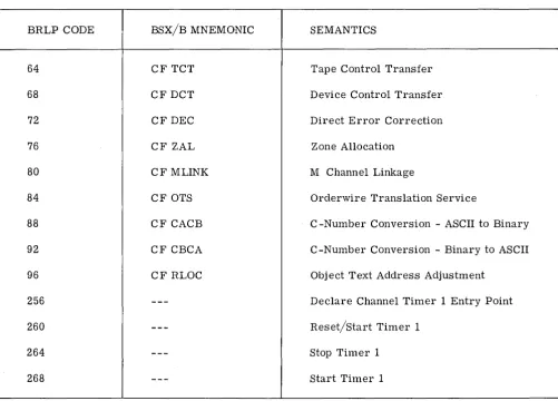
All programs executed in the privileged mode have access to all common functions. Programs executed in the unprivileged mode have direct access only to common functions for which a Branch and Set Return Link Protected (BRLP) code has been defined. The orderwire 1, orderwire 2 and S channels operate in the privileged mode while the A, Band M channels do not except through the BRLP )inkage. The following paragraphs describe the common function shown in figure 2-5.
2.3.8.1 Com"",,, Space Allocation and Release
Common space allocation and release routines allocate common core space to calling programs and release core space from the calling programs cognizance. Space is allocated in bin size of 4, 8, 16, 32, 64, 128, 256, and 512 words in length. Allocation of core space is provided by the common space allocate routine, and release of core space is provided by the common space release routine. These routines are privileged and cannot be called from outside protected memory except indirectly through other common functions.
2.3.8.2 Disc Fil" Storage Space Allocation and Release
Disc file space allocation and release is accomplished by a service function that provides housekeeping of allocated and released space and by common functions that interface with the channel programs. Disc file storage is partitioned into zones and each zone contains only one cell size. Cell lengths may be 128, 256, 512 or 2048 bytes. The number of cells within a given zone is a function of the cell size and the zone boundaries determined at initialization. Allocation of disc file storage zone space is provided by the zone allocation routine for allocating zones while allocation of disc file storage cell space within a zone is provided by the allocate cell routine. Documentation of active user files is provided by the document file routine. Release of a user file that was previously documented is provided by the release file routine which allows a complete file to be purged once it is declared inactive by the user.