Dieser Sonderdruck ist fur eine' b(!schrib;kt~ Verteibu1ig bestimriit. Die Wiedergabe des vorliegenden in ,,ENERGIA NUCLEARE'\ Vol. 9, N° 9, 1962, 529-5~4, erschienenen A't,1,fsatzes erfolgt mit freu.ndlicher
' Genehmigung des Herausgebers. Bestellungen weiterer,. Exemplare sind an ENERGIA NUCLEARE, Casella Postale 3986, Milano-IfJalia, zu richten.
Ce tire-a-part est exclusivement destine
a
I une diffusion restreinte. Ilreprend, avec l' aimable autorisatfon de,
"t
'
editeur, un a~tifle publie dans ,,ENERGIA NUCLEAR,E", Vol. 9, N° 9, 1962, 529-534. Tout I qutre exemplaire de cet article, doit etre d~mandea
ENER,GJ'ANU-CLEARE, Casella Fostale 3986, Milano-Italia.
Questo estratto
e
destinato esclusivamente ad una diffusione lirrtitata. GIA NUCLEARE", Vol. 9, No 9, 1962, 529-534.NERGIA
CLEARE
VOLlJ'IIIE 9
Jr'UIIIEBO 9
SETTEKBBE
1962
Design criteria.,
engineering features
and experimental
program
of the EOO reactor
P. Bonnaure, G. Casini, R. Cenerini, F. Toselli
Euratom OCR - Ispra (Varese)
energia nucleare, vol. 9 / n. 9 / settembre 1962
The critical facility EGO is intended for buckling measurements of the ORGEL lattices by the progressive substitution method, and for the . evaluation of other important neutron parameters of such lattices as tem-perature coefficients, reactivity change as a function of the burn-up, microscopic parameters, neutron spectrum. In this report, the criteria for the choice of the core parameters, some engineering features and the exper-imental program of the EGO reactor are detailed.
INTRODUCTION
The critical facility ECO (Essai Critique Orgel) is a low power assembly, intended for the experimental determination of the lattice parameters of the heavy water-moderated, organic liquid-cooled reactor (Or-gel), under study by the Euratom Common Research Center at Ispra.
The importance of correlating theoretical evalua-tions with experimental results arises from the fol-lowing considerations:
a) high accuracy from the calculations cannot be expected because of the complexity of the Orgel fuel element and the presence of an hydrogenated coolant,
b) in an Orgel type of reactor (as in any natural uranium reactor) uncertainties in the reactivity balance can produce noticeable effects on the de-velopment of the whole project and hence on the economy of such a reactor.
I. CRITERIA FOR THE CHOICE OF ECO CORE
PARAMETERS
To establish the size of the core vessel of ECO, we referred especially to the buckling measurements
N
e
326
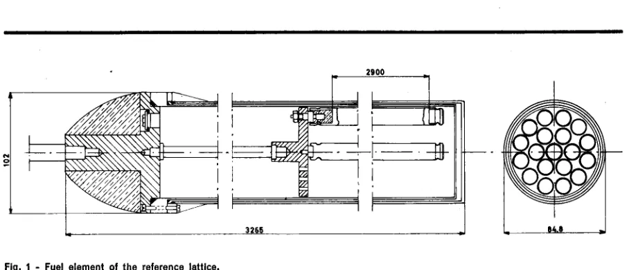
Fig. 1 - Fuel element of the reference lattice.
by the method of progressive substitution worked up at Saclay (France) 1,
This method consists in the progressive substitution of the reference elements located in the central zone of the reactor with the elements to be tested. The buckling of the reference lattice is measured by flux mapping; the difference LJB• between the
bucklings of the two lattices may be determined by measuring the variations of the D20 critical
level corresponding to each substitution.
The errors affecting LJB• are essentially of two types: errors independent to LJB•
They are connected with the uncertainty in the critical level measurements and are usually small (of the order of 0.02 m-2
) ;
errors proportional to LJB•
They come from the uncertainties m the extra-polated height, in the extraextra-polated radius, in the evaluation of the reflector coefficients and from the difficulty of adjusting the coupling coefficient between thermal and fast neutrons of the two regions of the core. This error is of the order of 374% of LJB•.
530
2900
a) Refiector
The first choice to be made was between a bare and a reflected reactor; the reflector produces a distortion of the neutron flux in the core boundary, thus limiting the number of points available for best-fitting radial and axial flux measurements. Furthermore, when interpreting the substitution measurements, the introduction of the so-called reflector coefficients is required in the reflected reactor to account for the variation of the reflector saving with the heavy water level. These reflector coefficients are calculated with a rather poor ap-proximation.
Otherwise, as the Orgel lattices have rather low bucklings (of the order of 2.5 m-2
) and owing to
the fact that the amount of heavy water to be supplied must be contained in reasonable limits, if one chooses a bare reactor one must accept high values of the buckling difference between << refer-ence » and « test » lattices.
As the reflector offers also a convenient housing for neutron flux detectors and control plates, a side and bottom reflected reactor was designed. However, a boral skirt, sliding between the core
[image:4.536.69.523.81.276.2]vessel and the reflector, allows for experiments with the radially bare reactor.
b) Diameter of the core vessel
The choice of the vessel diameter results from evaluating how it affects the following parameters: - heavy water supply,
- number, weight and height of the fuel elements, - reactivity equivalent of 1 mm height of heavy water,
- number of radial points available for best-fitting the JO function,
- thickness of the reference boundary zone when the radius of the test central zone is maximum.
It is easily understandable that there are opposite requirements; for instance, if the vessel diameter has a value in the range of 2.80 to 3.30 m, which is reasonable for the bucklings of interest, a low heavy water supply would require a small diameter.
If, on the other hand, fuel elements of excessive heights (which makes their handling difficult in substitution operations) are to be avoided, large diameter values would then be required. A 3 m diameter was considered to fulfil adequately the above requirements.
c) Fuel element of the reference lattice
The fuel element of the reference lattice was selected in such a way as to satisfy the experimental require-ments in a large range of lattices to be examined (by changing type and geometry of the fuel element, moderating ratio, etc.).
To obtain in the boundary region occupied by the reference lattice a neutron spectrum (and hence a moderating ratio) near to the one in the central region, the element chosen is similar to that of Orgel lattice, that is formed by a rod cluster con-tained in an organic liquid-filled aluminium tube. The main characteristics of the element (fig. 1), determined through a detailed parameter analysis, are the following :
number of rods
diameter of uranium metal rods thickness of aluminium cans
distance between cans of two adjacent rods
energia nucleare, vol. 9 / n. 9 / settembre 1962
19
12 mm
1 mm
1.2mm
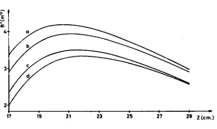
17 19 21 23 25 27 29 Z(cm.)
Fig. 2 - Buckling of the reference lattice vs. lattice pitch. Core temperatures of 20 •c (curves a, c) and 80 •c (curves b, d). Calandrla tube thickness of 1.5 mm (curves a, b) and 3 mm (curves c, d).
distance of the boundary rod cans from the calandria tube
thickness of the calandria tube
height of the active fuel region
2 mm
1.5mm 2900 mm
The organic liquid chosen is Dyphil (diphenyl 26.5%, di phenyl oxide 73.5%); its hydrogen atom concentration is near the one of Gilotherm OM
(the organic coolant probably used in Orgel). Dyphil has the advantage of being liquid at room tem-perature.
At intermediate pitch values, a small decrease of buckling may be useful to avoid too large buckling differences between the two regions. This can be achieved by mounting a second aluminium tube 1.5 mm thick, outside the first one.
Fig. 2 shows the lattice buckling as a function of the pitch, at 20
oc
and 80oc.
2. ENGINEERING FEATURES
a) Core, reflector, shielding
As mentioned above, the core of ECO is contained in a 3 m diameter aluminium tank. The cylindrical
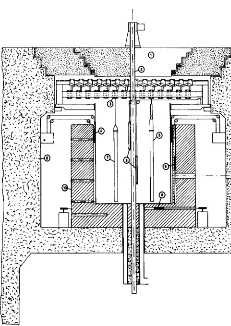
[image:5.535.253.472.115.246.2]wall of the tank is 10 mm thick; the base is 15 mm thick. The tank is surrounded laterally and under-neath by a thermal insulating liner and by a 90 cm thick graphite reflector (fig. 3).
A 6000 X 6000 X 1300 mm parallelepiped-shaped aluminium caisson is connected through a neoprene joint to the top of the tank. It contains the fuel element suspension mechanism formed by 17 lower rails bearing small carriages under which the fuel elements hang, guided by 17 upper rails placed at right angles with the others (fig. 4).
The rails move parallel and symmetrically with respect to the fixed central one by means of an array of articulated lozenges. In this way, it is possible to realize a continuously adjustable lattice pitch, from 180 to 300 mm, using only two driving devices.
In the caisson top there is a circular hole having a diameter greater than that of the tank, closed by a rotating cover of which two types are planned: one, 10 cm thick, to be used at zero reactor power; the other, 110 cm thick, to be used when operating at 1 kW (maximum reactor power). The cover has a radial slot which allows acces to every point of the reactor.
Reactor vessel and caisson are under a slight nitrogen overpressure to prevent from entry of atmosphere moisture which would degrade the
D20 isotopic concentration. Gas tightness is ensured
by means of an inflatable rubber seal adherent to the rotating cover.
The lateral shielding is achieved with a 1.70 m thick ordinary concrete wall. A passage between the reflector and the shield leads to flux detectors and control servomechanisms.
The caisson is provided with a barite concrete shield, representing with the cover the upper protection. This is completed by two 60 cm thick concrete plates, sliding on rails.
Shielding allows work around and over the reactor,
at 1 kW power.
b) Control and safety devices and subsidiaries
During the substitution measurements, control 1s carried out by varying the heavy water level. A
boral skirt, sliding between the tank and the re-flector, follows the heavy water level with its lower
532
•rd.'~ ·• ( ~-·)
}(;{J{ ·.
• • • . • t . ,
•r •· " \ . ' ·
{}\}j
;~~j l~~·>'--
..
\..
f_'.\:
-,..
--Fig. 3 - Reactor vertical cross section. 1) Rotating cover. 2) Cen-tral fuel element oscillating system. 3) Adjustable suspension system. 4) Boron skirt. 5) Heating fuel element. 6) Concrete. 7) Reference fuel element. 8) Safety rods. 9) Regulating plates. 10) Graphite.
edge, thus preventing neutron reflection beyond the free level of water.
Four plates (two vertical and two horizontal), sliding into holes in the reflector, allow automatic control of the reactor power. The horizontal plates are necessary in operations in which the boral skirt, which shields the vertical plates by making the reactor radially bare, is lowered.
The safety apparatus consists of two stainless steel-sheathed boron carbide rods, which may fall by gravity into the centre of the core. In addition, a
[image:6.535.305.531.115.434.2]remote controlled valve opens when either the power is too high or the period too short, permitting rapid (10 m•/min) evacuation of the tank.
Several circuits are contemplated for heavy water: filling and emptying of tank, purification by means of ions exchange resins, heat exchangers and heaters for measurements at several temperatures. Dosed amounts of heavy water may be introduced into or drawn out of the tank by means of calibrated vessels.
A special apparatus measures the level of heavy water in the core with a very good precision (0.2 mm error). A device for measuring and continuously recording the heavy water isotopic concentration is also provided.
The building housing the reactor is furnished with three overhead cranes: one of 50 tons and two of 5 tons. Furthermore, a 300 kg telescopic crane permits easy loading and unloading of fuel elements from the reactor and their location in a special storage beside the reactor. A metallic structure permits an easy assembling or manipulating of the unirradiated fuel elements. A cell, containing suitable pliers and master slave manipulators, is contemplated for the irradiated fuel elements. It is, thus, possible to take away the detectors ar-ranged in the elements and irradiated for a long time, to perform the measurements of the micro-scopic parameters of the lattice.
3. EXPERIMENTAL PROGRAM
Buckling measurements by the substitution method will be performed initially for unirradiated Orgel lattices.
In
this first step, the effect of all geometrical and engineering parameters of the lattice on the neutron balance will be studied, the isotopic com-position of the fuel (natural uranium) being kept constant.These data are certainly inadequate, because they are related to one particular condition of the reactor life, i.e. to his start-up.
A second step will introduce the use of synthetic fuel elements in which slight modifications in the fuel composition will be effected, e.g. substitution of small amounts of U-235 with Pu-239.
Thus, a comparison of several fissile nuclei in a set of very different spectra may be obtained.
energia nucleare, vol. 9 / n. 9 / settembre 1962
Finally, in the last step the measurements will be performed on the irradiated elements of the Orgel reactor. This is necessary because the synthetic fuels and the irradiated ones differ by:
a) the spatial distribution of the nuclei, which modifies, for instance, the shadow effect for the resonances captures of Pu-240 and the hardening of the neutron spectrum from the boundary towards the centre of the fuel rods;
b) the presence and the distribution of the fission products that it is difficult to obtain in a synthetic fuel.
The high cost of synthetic fuel elements and the difficulties in handling a great number of irradiated elements, as is necessary in integral measurements
-
qJ\JI!',!'.., , !', !', ~ !', ~ ~ p.,,,,.
/I--
~li ll :\ \j )j li l I ¥ li \j ~ \j It \j \j 1 'i I\ l
11
f
I
0:: .JO
"'
_;,o"' _;,o
""
a:: ... v I'
....
-"',c: .JO
"' -"'
"" ::,0
"' _;,o .,. ..,, I/ I\ .._
_,..
a:: ::,,
..
.,...
"' ::,0
.
_::,o...
.
.-"'-....
..
-"'"" ::,0
..
..,...-
...
.
--ex:: ::,0
.
..,."" CD
" ::,a
..- ... \ I
-
.;,aoC ell
...
..,. [image:7.540.256.471.369.597.2]re :o " _;,o
...
'
/•
.-"'oC ell
-
-
.
-"',,. ::,0 "- -"'
i
l
II II R R J\J\ /1.P
i
I
II !', J\ J\ IJ\ II II A R
/I "
---=-
,__n11 ll \j )Ill ll \j \j 'd ll li \I ll ~ );
Fig. 4 - Sketch of the pitch changing mechanism.
with the substitution method, have suggested an experiment from which the behaviour of the neutron properties with burn-up may be determined by a single rod analysis. With this aim, the oscillation of the central rod of ECO is being devised through the employment of a toothed wheel mechanism now under study.
The flux modulation method may present diffi-culties in the interpretation of data, but we hope that they will be partly overcome by limiting us only to comparison measurements.
On the other hand, this method allows a very
sen-sitive evaluation of differential effects, if one re-duces the noise error by proper choosing of the du-ration of the oscillation experiment and if the reactor power does not present appreciable drifts. This method permits the analysis to be limited to small samples, which are therefore in neutron spec-trum conditions well-defined by the surrounding lattice.
In ECO, provision is made also for the measurement of the temperature coefficients ( of the organic liquid, of the moderator, etc.). It is possible to heat the whole core up to 80 °C by means of a heavy water circuit; the water is let in through a series of holes in the boundaries of the tank bottom, and let out through an annular tube placed in the middle of the bottom.
As the organic liquid is a rather strong neutron absorber, there is the possibility to have a fast positive coefficient of temperature; to determine this temperature coefficient, substitution experi-ments will be performed with special fuel eleexperi-ments, in which the organic liquid may be heated up to 250 °C by means of heating resistors and circulated by a pump.
The experimental program on the ECO reactor in-cludes the study of the behaviour to a pulsed source. For this purpose, a 1 Me V Van der Graaff accelerator is provided. The pulses may have length from 10 to 3000 µs with a frequency from 1 to 1000 p · s-1•
The accelerated particles are deuterons and the target will be mostly beryllium, but the possibility of using lithium target is also foreseen. Beryllium was preferred to tritium because it has a much longer lifetime and the neutrons from the reaction Be• (d, n) B10 have maximum energies of 5 Me V.
534
The neutrons from the reaction T (d, n) He have energies up to 10 Me V, whilst the experiments will concern mostly thermal neutrons.
The ionic current obtainable depends upon the working conditions of the accelerator: it is of 1 mA for continuous working condition, but it may rise up to 5 mA in pulse conditions. In the first case, a beryllium target would produce 1011 neutrons/s, and a lithium one 2, 1011 neutrons/s.
To develop an exhaustive correlation between the calculation methods and the experimental deter-minations of the buckling, thermal utilization factor, resonance escape probability, fast fission factor, initial conversion factor will be measured systematically.
Owing to the importance of the neutron spectrum problems in an Orgel-type reactor, in which the coolant and the moderator are at different tem-perature, measurements of the spectrum will be performed both by selective detectors and the time-of-flight technique. For the latter purpose, radial aluminium tube will allow the extraction of a neutron beam, to be analyzed by a time-of-flight selector. In this experiment, the reactor power will be kept at 1 kW, in order to obtain flux of about 10• n/cm2 s. •
bibliography
1 Y. GIRARD et al.: Natural Uranium - Heavy Water Lattices.
P/336, Proc. Geneva Conference (1958), vol. 12.
riassunto
CRITERI DI PROGETTAZIONE, CARATTERISTICHE TECNICHE E PROGRAMMA SPERIMENTALE DEL REATTORE ECO
La struttura critica ECO