International Journal of Emerging Technology and Advanced Engineering
Website: www.ijetae.com (ISSN 2250-2459,ISO 9001:2008 Certified Journal, Volume 3, Issue 5, May 2013)
190
Metal Forming Analysis
Prof. N. C. Mehta
1, Viral V. Shiyani
2, Jemish R. Nasit
31
Head of Department, Department of Mechanical Engineering, Noble Engineering College, Junagadh, Gujarat,
2,3
Mechanical Engineering Student, Noble Engineering College, Junagadh , Gujarat,
Abstract—There are a wide range of physical defects which occur during metal forming processes. These defects, which may occur on the surface or be internal, are undesirable not only because of the surface appearance, but because they may adversely affect the strength, formability and other manufacturing characteristics of the material. Some physical defects in metal forming processes such as rolling and forging, Defects in forging reduce its strength. Appreciable residual stresses and warping can occur on the quenching of steel forgings in heat treatment. They occur for a number of reasons including faults in original metal, incorrect die design, improper heating and lubrication. Defects of forged product include exterior cracking, interior cracking, laps, cold shuts, warping of the part, improperly formed sections and dead zones. In this project we will analysis the metal of forging and try to reduce metal defects in forging processes. Finite element analysis is used to predict residual stresses in forgings .The objective of this project is to obtain an optimal billet shape in the consideration of the metal flow deformation in closed die forging process. Finite element method in conjunction with optimization algorithm was used to analyze the effect of billet shape on forging load in axisymmetric closed for die forging process.
ANSYS was used to simulate closed die forging process and then performing a series of optimization iteration in order to obtain the optimal shape of the billet based on forging load minimization. The material used is aluminum metal matrix composite (ALMgSi matrix with 10% SiC particles). The goal of the simulation and optimization process is to minimize the forging load and produce crack-free forgings. The optimal shape of the billet that gives minimum forging load was obtained after several optimization iterations. The approach used in this study could be extended to the optimization of more complicated forging product. Due to the advances in computer technology based finite element software, the forging load can be easily estimated which is iterative process in the old technique of prototype built up and destructive testing. In the present work consideration 3 critical design parameters with critical plastic strain limit as the state variable and keeping the forging load as the objective function and the billet shape is optimized for different diameter to height.
Keywords-- Die Forging, Finite Element Method, Metal Matrix Composites, Optimization , induction forging, finite element analysis, residual stresses in forging.
I. INTRODUCTION
1.1 Forging process [1-3]:
Forging is a manufacturing process that involves applying compressive forces to a work piece to deform it, and create a desired geometric change to the material. Forging, similar to other forming processes, affects the properties of the material of the forged product. Specifically, forging can strengthen the material by eliminating cracks and empty spaces within the metal. Forging a metal will also alter the metal's grain structure with respect to the flow of the material during its deformation. The forging process can be used to create favorable grain structure in a material greatly increasing the strength of forged parts. For these reasons, forging manufacture gives distinct advantages in the mechanical properties of work produced, over that of parts manufactured by other processes such as casting or machining.
Forging processes can be classified by the degree to which the flow of the material is constrained during the process. There are three major classifications in forging manufacture. Open die forging, in which the work is compressed between two die that do not constrain the work during the process. Impression die forging, cavities within the die restrict metal flow during compression of the part, causing the material to deform into a desired geometric shape.
1.2 Description of Problem:
There are a wide range of physical defects which occur during metal forming processes. These defects, which may occur on the surface or be internal, are undesirable not only
because of the surface appearance, but because they may
adversely affect the strength, formability and other manufacturing characteristics of the material.
International Journal of Emerging Technology and Advanced Engineering
Website: www.ijetae.com (ISSN 2250-2459,ISO 9001:2008 Certified Journal, Volume 3, Issue 5, May 2013)
191 Cracking both interior and exterior is caused by excessive stress, or improper stress distribution as the part is being formed. Cracking can be a result of poorly designed forging die or excess material in the work piece. Cracks can also be caused by disproportionate temperature distributions during the operation. High thermal gradients can cause cracks in a forged part.
Laps or folds in the forging are caused by a buckling of the part; laps can be a result of too little material in the work piece. Cold shuts occur when metal flows of different temperatures meet; they do not combine smoothly, a boundary layer, (cold shut), forms at their intersection. Cold shuts indicate that there is a problem with metal flow in the mold as the part is being formed. Warping of a forged part can happen when thinner sections cool faster than the rest of the forging. Improperly formed sections and dead zones can be a result of too little metal in the work piece or flawed forging die design resulting in incorrect material distribution during the process
II. LITERATURE REVIEW
S.L.WANG, K.P.RAO, X.Y. CUI ,G.Y. LI, X. PANG and BALENDRA have done research work on metal forging analysis. In the metal analysis of forming processes, knowledge of friction is important, especially when the
microstructure evolution and criteria for limiting
phenomena are predicted by numerical simulation. The friction wave model has been studied by several researchers. Their analyses are mainly based on the assumption that there is no plastic deformation of the bulk material. However, it is necessary to clarify the influence of bulk material deformation on the surface asperity deformation. This paper deals with the development of a friction wave model by considering the influence of bulk material on the surface asperity deformation. The situation of rough tool smooth work piece contact during forming process has been investigated. Based on this condition, an admissible velocity field is constructed for the upper bound analysis. The relationship between the normal pressure and the sliding resistance is established over a large range of pressure. The role of surface roughness, bulk displacement and bulk strain on metal forming friction is analyzed.
Forming processes play an important role in metal part
manufacturing. Numerical simulation is a cost-effective
technique which can be used to examine new metal forming process and to predict possible manufacturing difficulties and forming defects including localized bifurcation, micro cracks, wrinkles, surface damage and geometrical inaccuracies.
At the tool/die design stage, numerical simulations prior to experimentation minimize the traditional ‘trial and error’ iterations, and enable the engineers to avoid costly prototypes. The usefulness of computer simulation techniques in the design and manufacturing processes of metal forming are becoming widely recognized. The simulation of metal forming problems involves geometric, material, and contact non-linear, and thus requires advanced numerical techniques.
The quality of metal formed parts is affected by factors such as the forming machinery, the tooling, the friction, the temperature and the material properties, a detailed under- standing of these parameters being essential to manufacture- in analysis using currently available FEM software.
The accuracy of an analysis depends on the constitutive model adopted. Currently available FEM software provides general constitutive models that do not replicate the cost - tutivebehaviour of work-material subjected to complicated deformation histories. In metal forming, the work-material experiences finite elastoplastic deformation, complex
hard-ending, plastic strain induced anisotropy, plastic
deformation induced heat, variation in temperature and consequent thermal influences on material properties, and possibly phase-transformation, strain-rate effects or viscoelastic de-formation, variation in microstructure, damage and fracture. Several models have been proposed to define the con- stitutivebehaviour of materials subjected to multi-axially non-proportional loading, but few of them were ex-tended to them. Case of finite elastoplastic deformation for ape-plication to metal forming analysis.
III. PREPROCESSING OF FEAUSING ANSYS
The accurate simulation of cylindrical billet die is done for finding out load distribution and stress distribution by using proper solving conditions. These solving conditions include initial and boundary conditions, material properties and assumptions etc. Finite Element Analysis using ANSYS was performed and The billet is represented with initial radius and the height to calculate load field and
stress field caused by application of the volume of the die
cavity.
3.1 Analysis Model
Based on drawing and dimensions available from
kadvani Forge Limited, a model is developed using Pro E
International Journal of Emerging Technology and Advanced Engineering
Website: www.ijetae.com (ISSN 2250-2459,ISO 9001:2008 Certified Journal, Volume 3, Issue 5, May 2013)
192 We had converted this model in iges format which is universal format for all modeling software then it is imported into ANSYS.
3.2 Mesh size selection
We have done coupled field dynamic analysis using different mesh size and found that with the increase in mesh density stress is decreasing up to an optimum value but then if we go for more mesh density then stress will increase. Contact elements are defined between die and billet interface, billet and container interface. Targe169 and Conta172 elements are used for representation. Contact manager is used to build the contact pairs between the members. Target elements are the rigid elements and contact elements are the flexible members. Separate contact pairs are created with reduced penetration tolerance. A friction model of 0.1 is used for simulating the problem. Maximum vonmises stress of 330Mpa can be observed in the problem. Contact elements are the surface elements which have the algorithm to represent possible sliding and penetration which movement of the members relative to each other. The die nodes are used to apply the displacement loads. Contact elements uses Lagrange approach for better results. The status of contact, contact penetration, sliding etc. can be observed in the contact simulation. So we understand that we are going away from the answer so that we had selected normal mesh density. If we go for very fine meshing or very course meshing we will go away from the accuracy. So that we had selected mesh density which will give be more nearer to the actual value. Thus we had found out mesh density.
3.3 Initial and Boundary conditions, material properties and basic assumptions:
To solve this forging defects problem of cylindrical billet die, the following initial and boundary conditions, material properties and basic assumptions are made:
Refractory Materials for cylindrical billet die meets
the basic assumptions in the science of mechanics.
Environmental Temperature is homogeneous at 25° C.
Ignore the influence of heat convection.
Ignore the effect of gravity field.
The surface of cylindrical billet die is clean.
The initial temperature of the cylindrical billet die is
set 25° C and it is agreement with the ambient temperature during solving the problem.
billet material is considered uniform for our analysis.
Calculation of Force Reduction:
1)
% of volume reduction :=
(
Vexperimentally – Vanalysis)
/ V experimentally= (38910.528 – 34587.89) / 38910.528 = 0.1110
2) Force Reduction :
= F experimentally – F analysis
=
115.758 – 106.250 = 9.580 KNIV. RESULTS AND DISCUSSION
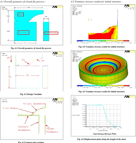
Two dimensional geometry is represented for die, container and billet are shown with dimensions in figure 1. All major initial dimensions are represented in the problem. Ansys mixed approach is used to built the geometries. For die shape, bottom approach and other geometry top down approach is used in the problem. The geometry is built as per the dimensions and connectivity is not maintained to carry nonlinear large deformation contact analysis to simulate closed die forging process.
Analysis results for vonmises stresses are presented above. Maximum vonmises stress of 330Mpa can be observed in the problem. Left picture is represented in 2dimensional domain and right side picture is represented in three dimensional domains.
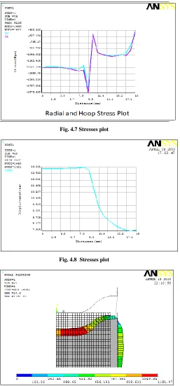
The results are shown in figure for radial, hoop and vonmises stresses. Similar stress pattern can be observed for radial and hoop stresses. But vonmises stress is high in the beginning and later reducing along the path of the top nodes. Maximum stresses can be observed in the higher deformation regions where the members reaches to plastic state and lesser stresses in the lower deformation regions.
Material used in forging process :
Al Mg Si SiC Density(gr/cm3)
International Journal of Emerging Technology and Advanced Engineering
Website: www.ijetae.com (ISSN 2250-2459,ISO 9001:2008 Certified Journal, Volume 3, Issue 5, May 2013)
193
4.1 Overall geometry of closed die process :
Fig. 4.1 Overall geometry of closed die process
Fig. 4.2 Design Variables
Fig. 4.3 Contact pair creation
4.2 Vonmises stresses results for initial structure :
Fig. 4.4 Vonmises stresses results for initial structure
[image:4.612.47.578.123.682.2]Fig. 4.5 Vonmises stresses results for initial structure
International Journal of Emerging Technology and Advanced Engineering
Website: www.ijetae.com (ISSN 2250-2459,ISO 9001:2008 Certified Journal, Volume 3, Issue 5, May 2013)
[image:5.612.48.305.121.672.2]194
[image:5.612.320.570.125.428.2]Fig. 4.7 Stresses plot
Fig. 4.8 Stresses plot
Fig. 4.9 Contact Pressure in the problem
Analysis Table :
V. PREDICTION OF FATIGUE LIFE
5.1 Fatigue Life Methods [19]
The three major fatigue life methods used in design and analysis are the stress-life method, the strain-life method, and the linear-elastic fracture mechanics method. These methods attempt to predict the life in number of cycles to failure, N, for a specific level of loading. Life of 1 ≤ N ≤ 103 cycles is generally classified as low-cycle fatigue, whereas high-cycle fatigue is considered to be N > 103 cycles. The stress-life method, based on stress levels only, is the least accurate approach, especially for low-cycle applications. However, it is the most traditional method, since it is the easiest to implement for a wide range of design applications, has ample supporting data, and represents high cycle applications adequately.
International Journal of Emerging Technology and Advanced Engineering
Website: www.ijetae.com (ISSN 2250-2459,ISO 9001:2008 Certified Journal, Volume 3, Issue 5, May 2013)
195 The fracture mechanics method assumes a crack is already present and detected. It is then employed to predict crack growth with respect to stress intensity. It is most practical when applied to large structures in conjunction with computer codes and a periodic inspection program.
5.2 The Stress-Life Method
To determine life of any component by Stress-Life Method, we need to find out ultimate strength and endurance limit of the component for the required material.
We know the values of ultimate stress for these all materials. Al mass is having ultimate strength of 330 Mpa. We can find out Se’ from the equation given below or we can say dividing value of ultimate strength.
We know value of ultimate stress of the material.
Material Sut (MPa)
Al mass
330
We know the relation between Sut and Se’ so that we can find out Se’.
Se’ = 0.5 * Sut
Endurance Limit Modifying Factors:
We have seen that the rotating-beam specimen used in the laboratory to determine endurance limits is prepared very carefully and tested under closely controlled conditions.
It is unrealistic to expect the endurance limit of a mechanical or structural member to match the values obtained in the laboratory.
Some differences include
Material: composition, basis of failure, variability
Manufacturing: method, heat treatment, fretting
corrosion, surface condition, stress concentration
Environment: corrosion, temperature, stress state,
relaxation times
Design: size, shape, life, stress state, stress
concentration, speed, fretting, galling
Marin identified factors that quantified the effects of surface condition, size, loading, temperature, and miscellaneous items. The question of whether to adjust the endurance limit by subtractive corrections or multiplicative corrections was resolved by an extensive statistical analysis of a 4340 steel, in which a correlation coefficient of 0.85 was found for the multiplicative form and 0.40 for the additive form.
A Marin equation is therefore written as
Se = ka*kb*kc*kd*ke*kf* Se’
Where, ka = surface condition modification factor kb = size modification factor
kc = load modification factor kd = temperature modification factor ke = reliability factor
kf = miscellaneous-effects modification factor Se’= specimen endurance limit
Se = endurance limit at the critical location of a machine part in the geometry and condition of use
We can find out different as per the guideline given in
the Machine Engineering Design by Shigley.[19]
Surface Finish Factor ka 0.86
Size Factor kb 1
Loading Factor kc 1
Temperature Factor kd 0.25
Reliability Factor ke 0.9
Miscellaneous Effects Factor kf 1
Now, we can find out endurance limit for all different materials.
Se = ka*kb*kc*kd*ke*kf*Se'
VI. CONCLUSION
Introduction of metal forming are highly used now- a-days for generate a die and billet shape by forging process of different kinds of materials.
There are a wide range of physical defects which occur during metal forming processes. These defects, which may occur on the surface or be internal, are undesirable not only because of the surface appearance, but because they may adversely affect the strength, formability and other manufacturing characteristics of the material. Some physical defects in metal forming processes such as rolling and forging, Defects in forging reduce its strength.
International Journal of Emerging Technology and Advanced Engineering
Website: www.ijetae.com (ISSN 2250-2459,ISO 9001:2008 Certified Journal, Volume 3, Issue 5, May 2013)
196 Cracking can be a result of poorly designed forging die or excess material in the work piece. Cracks can also be caused by disproportionate temperature distributions during the operation. High thermal gradients can cause cracks in a forged part
Finite element analysis in conjunction with optimization techniques, are used to develop a system for the design of optimal billet height/diameter ratio of closed die forging process. The finite element model was built parametrically
using ANSYS parametric design language. The
optimization billet shape optimization for minimum forging load module used the analysis file to search for minimum objective function (Forging load by changing) billet height/diameter ratio.
REFERENCES
[1 ] Edwards, L. and Endean, M., Manufacturing with materials process,
1999, Arnold, ISBN 0-470-35241-8.
[2 ] Lange, K., Handbook of metal forming. 1919. McGraw-Hill Book
Company, ISBN 0-07-036285-8.
[3 ] Kobayashi, S., Oh, S-I. and Atlan, T., Metal-Forming and the
Finite-Element Method. Oxford University Press, Oxford, 1989.
[4 ] Schey, J. A., Tribology in Metalworking Friction, Lubrication and Wear. American Society of Metals, Metals Park, Ohio 44073, 1983.
[5 ] Ramaekers, J. A. H. and Kals, J. A. G., Mathematical representation
of friction in metal-forming analysis. Ann. CIRP 1986, 35(1), 167 180.
[6 ] Bay, N. and Wanheim, T., Contact phenomena under bulk plastic
deformation. Proceedings of the 3rd International Conference on Technology of Plasticity, Adv. Tech. Plasticity, Kyoto 1990, 4, 1677 1691.
[7 ] Avitzur, B. and Nakamura, Y., Analytical determination of friction resistance as a function of normal load and geometry of surface irregularities. Wear, 1986, 107, 367-383.
[8 ] Avitzur, B., Huang, C. K. and Zhu, Y. D., A friction model based on
the upper-bound approach to the ridge and sub layer deformations. Wear, 1984, 95, 59-77.
[9 ] thelibraryofmanufacturing.com
[10 ]Dieter, G.E., Mechanical metallurgy, 1988, SI metric edition,
McGraw-Hill, ISBN 0-07-100406-8.
[11 ]Edwards, L. and Endean, M., Manufacturing with materials, 1990, Butterworth Heinemann, ISBN 0-7506-2754-9.
[12 ]Beddoes, J. and Bibbly M.J., Principles of metal manufacturing
processes, 1999, Arnold, ISBN 0-470-35241-8.
[13 ]Lange, K., Handbook of metal forming, 1919, McGraw-Hill Book