Using Evaporative Cooling Methods for Improving
Performance of an Air-cooled Condenser
Mohammed H. Alhamdo
*, Maathe A. Theeb , Jaafar J. Abdulhameed
Department of Mechanical Engineering, College of Engineering, Al-Mustansirya University, Iraq
Copyright © 2015 Horizon Research Publishing All rights reserved.
Abstract
In areas with very hot weather conditions (50 to 60℃), the temperature and pressure of the air-conditioning condenser are increased considerably. This causes a decrease in the cooling capacity of the cycle and also causes an increase in the power consumption due to increased pressure ratio. In this work, an experimental and theoretical investigation has been done to improve the evaporator outlet fluid temperature through enhancing condenser performance. For this purpose, several modifications on the refrigeration system have been developed and tested to solve this hot weather problem. The air-side modifications include adding Spray Water above condenser (SW), wet Pad before condenser (Pad), and water Vapor Nozzle in the condenser air flow (VN). The refrigerant-side modification includes adding a pair of Heat Exchangers (HE) for exchanging heat between condenser exit and evaporator exit by using water-antifreeze mixture as a working fluid. A Water-Refrigerant(W-R) evaporator has been designed, manufactured, and compared with original Air-Refrigerant(A-R) evaporator performance. All air and refrigerant-side modifications have been investigated using both types of evaporators. The results indicate that the (SW) modification for enhancing condenser performance is the best method for COP improvement. The COP of (SW) system is found to increase at rate of (44.5 %) and (102.1%) as compared to system without modifications for (A-R) and (W-R) evaporators respectively. The outlet cooling temperature from evaporator has been found to reduce by about (30.3%) for (A-R) evaporator and (23.6%) for (W-R) evaporator. However, (HE+Pad) modification has been found as the best method for improving air side Nusselt number of condenser with an increase of about (4.7) times that of system without modifications. Ten new Nusselt number correlations have been predicted for each type of modifications under investigation by using both Engineering Equation Solver (EES) software and the experimental data. Cost-Benefit analysis in terms of life cycle cost, net present value, cost-benefit ratio, and payback period have been conducted. From the analysis, it can be concluded that using (SW) system will save a significant amount of energy with a payback period of less than five years.Keywords
Condenser, Nusselt Number, Spray Water,Wet Pad, Vapor Nozzle
1. Introduction
Air conditioning systems are considered as an indispensable for life requirements. Most of them are based on vapor compression systems that using R-22 with window type, split units, chillers and heat pumps. Three main types of condensers used in these units are; air cooled, water cooled and evaporative cooling towers. Because the cooling medium (air) is a natural and free source, the air cooled
condensers (fin and tube heat exchangers) mostly used for
low and average refrigeration capacities. In these air cooled condensers, the power consumption is a major issue in vapor compression cycle. The power consumption concern increased much more if the air-cooled condensers work in area with very high ambient temperature (between 50-60 ⁰C), as it happens in many Middle East countries. In this area, the temperature and pressure of the air-cooled condenser will increased considerably. This causes an increase in pressure ratio which increases the power consumption of the air conditioner. Also, when the pressure increases, the pressure limit in control system will shut down the compressor. The increase of the condenser temperature will decrease the cooling capacity of the cycle due to the reduction of liquid content in the evaporator. So, the high pressure and temperature of the air-cooled condenser will decrease the performance of the air conditioner considerably [1].
This field has been thoroughly investigated both experimentally and numerically, and the contributions are available in the literature. Payne and Domanski [2] explored
the influence of increasing environmental temperature on the performance and pressure drop in the split air conditioning systems using R-22 and R-410a with no modifications. Michalis et al. [3] utilized an evaporative condenser working
water circulation ahead of the air condensation unit to develop evaporative condensation. They deduced that the evaporative condenser has higher performance compared to the air cooled condenser and that the higher the environmental temperature the more is the enhancement. Tissot et al. [5] studied sprayed air flow numerically. They
have explored droplet evaporation and air temperature under different loading conditions, solution and spray features. They found that using very fine droplets ranging between 25
and 50 μm results in a significant air cooling. Optimal
conditions have between sought regarding their size, as too small droplets where found to flow in a concentrated manner with a poor dispersion ability resulting in a less effective mixing, despite their better expected capacities when considered as individual particles. The counter flow injection is found to provide a more efficient cooling of the air. A study of heat transfer enhancement using an air flow containing water droplets across a heat exchanger has been carried out by Boulet et al. [6]. They showed that spray
implementation increases the rate of heat exchange, and recommended further investigations to be carried out for predicting the gains. Moreover, recently Wen et al. [7] argued
that evaporative cooling has not been covered properly in spite of the vast developments in split air conditioning systems and the advantages in power saving resulting by using air-cooled condensation.
As far as known, there is no previous work investigating the response of various modifications on the same air-conditioning system (i.e. under identical boundary conditions). Also, there is no previous work investigate the effect of merge several modifications at the same time on the same system. Further, unlike the conventional air cooled condensers, there is a lake for heat correlations that related to air-cooled condensers fitted with various evaporative cooling methods and subjected to high ambient temperature at the same time. Keeping the above in view, the main objectives of this work include;
Investigating the effects of different modifications on the performance of an air-conditioner working at high ambient temperature with an air-cooled condenser. The modifications include adding;
Nozzle for injecting, small water Vapor droplets (VN) in the condenser air stream. Wet Pad before condenser (Pad).
Direct Spray Water (SW) above the condenser. A pair of Heat Exchangers (HE) within the
refrigerant cycle, one before expansion valve and the other after evaporator.
Using (EES) software to develop a computer program for predicting the system thermal performance for each type of modifications.
Design and Manufacture of a Water-Refrigerant (W-R) evaporator for comparing its effects on system performance with that of an air-cooled evaporator. Propose a developed method for evaluation of new
Nusselt number correlations for each type of the modified air-cooled condenser under investigation.
2. Basic Equipment Layout
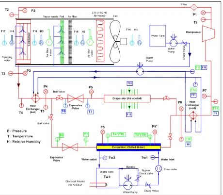
The equipment layout of this work is shown in Figure (1). Four types of modifications have been added to the main system for enhancing the condenser performance at high ambient temperature. The air duct of condenser includes the condenser enhancement methods Nozzle to inject Water vapor in condenser air flow (VN), wet Pad before condenser (Pad) ad Spray Water above condenser (SW). In this work, several computer programs in Engineering Equation Solver (EES) have been written for each type of the modifications. It should be noted that thermo-physical properties of R22 is already built into the software [8].
A water pump is used to raise the water pressure and causes the water vapor to exist from the nozzles. The volume flow rate of the water that used in these three modifications processes is fixed and measured continuously, and the water evaporation for these systems is also estimated. The (VN) modification process makes the condenser air flow to contain an evaporated water droplet for increasing the heat transfer. The (VN) produce very small droplets (below 25μm in size) which injected in a counter flow to the air stream direction for an optimal evaporation result. For (SW) modification, the initial experimental investigations show that the optimum condenser cooling performance would be achieved when the nozzle is located about (4.5 cm) above the top surface of condenser coil.
Figure 1. Basic Equipment Layout
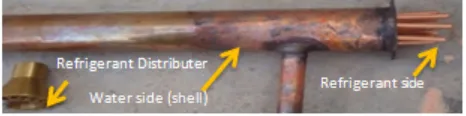
Figure 2. Water-Refrigerant double pipe Heat exchanger
[image:3.595.61.294.643.701.2]The original evaporator of the air-conditioning unit has been replaced by two types of evaporator, the first one is air-cooled, split type, while the second is water cooled, shell and tube type. Both of the evaporators have the same cooling capacity of the original one. In this work, both of the Water-Refrigerant (W-R) evaporator and Air-Refrigerant (A-R) evaporator have been used with all types of modifications. Figure (3) shows the shell and tube, chilled water evaporator that has been designed and manufactured locally to use in this work.
Figure 3. The manufactured water cooled evaporator
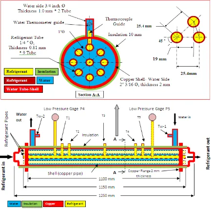
Figure 4. Dimensions of the Shell and tube (W-R) evaporator
In this work, a controlled (2x2x2 m) insulated test room has been built to include the evaporators. The condenser units with all types of modifications are placed in another controlled space for simulating the desired high ambient temperature. An air duct with cross section area of (46x35 cm) and depth of (90 cm) has been used to insert the condenser modifications. Since the air-cooling condensers are most common for residential air-conditioning applications, a (450x340x40 mm) staggered Z-type finned tube condenser has been used. The condenser have (26) horizontal pipe rows of (45 cm) length and diameter of (3/8 in) with vertical and horizontal spacing between pipes centers of (2.7 cm).
The weather conditions during all tests in the present study were the same. Data were recorded after a steady state condition was established in the system and the properties of refrigerant and air remained constant. Four digital humidity sensors have been used to measure the humidity at different
For each modification type, all experiments were performed at least twice (on different days), to check the repeatability of the data, which was proved to be good. Because the data demonstrated repeatability, only results one of the test will be presented here. The uncertainties for important parameters and measurements made during the current
[image:5.595.77.537.160.562.2]research have been carried out on the basis of the method proposed by Moffat [9]. The maximum uncertainties are ±2.73% for refrigerant Reynolds number, ±2.14% for water Reynolds number, ±1.88% for air Reynolds number, ±3.97% for Nusselt number, ±0.78% for fluid temperature, and ±3.81 for rate of heat transfer.
3. Results
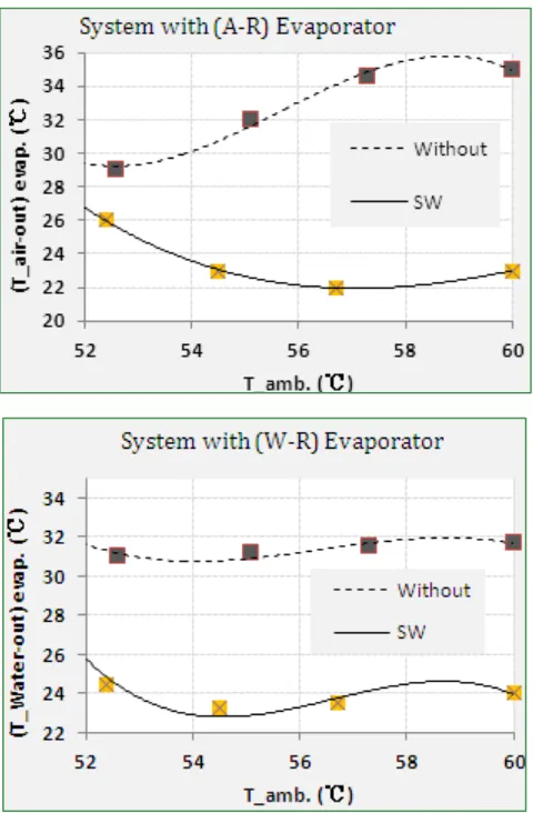
Figure (6) shows the effect of increasing outside ambient temperature on both exit air temperature from (A-R) evaporator and water temperature from (W-R) evaporator. This figure shows comparison between refrigeration system response without modification and system with spray water (SW). It is clear that there is an obvious drop in (Ta o)evap. and
(Tw o)evap. with increasing (Tamb.) as compared to system
without modifications. This behavior is due to the effect of directly spray water on condenser coil that causes drop in both condenser temperature and pressure.
Figure (7) shows comparison between refrigeration system responses using various types of modifications. As compared to other types of modifications under investigation, the (SW) modification is found to be as the best type. As compared to system without modifications, the decrease in (Ta o)evap. with (SW) modification is found about (30.3%) for
system with (A-R) evaporator and decrease (23.6%) in (Tw o)evap. for (W-R) evaporator.
[image:6.595.311.551.85.505.2]
Figure 6. Effect of increasing ambient temperature on the exit fluid temperature from evaporator for system with (SW) modification
Figure 7. Effect of increasing ambient temperature on exit fluid temperature from evaporator
Figure (8) shows comparison between the p-h diagram of system with (SW) and system without modification using (A-R) evaporator. It is clear that the system pressure and temperature for (SW) is better than that without modification. Also it seems that the (Q_H) and (Q_L) with (SW)
modification are greater than that of system without modification. It is found that the consumed power of the compressor has been reduced to about (75.1%) of system without modifications.
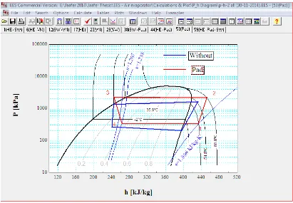
Figure (9) shows the p-h diagram for system using (Pad) modification for (A-R) evaporator. It’s clear that (Q_L) and
(Q_H)of system with (Pad) are more than that of system
[image:6.595.58.298.328.694.2]Figure 8. Comparison between P-h diagram of system with (SW) and system without modifications
[image:7.595.99.510.388.673.2]Figure 10. Comparison between P-h diagram for system with (HE) and system without modification
[image:8.595.115.496.82.346.2]Figure 11. Comparison between P-h diagram of system with (SW+VN) and system without modification
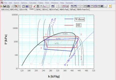
[image:8.595.112.498.370.642.2]Figure (10) shows the p-h diagram for system using (HE) modification with (A-R) evaporator. It is clear that the compressor pressure increased with superheated & sub cooled temperatures. Also, the compressor work has been reduced about (87.5 %) as compared to system without modifications.
Figure 12. comparison between P-h diagram of system with (HE+Pad) and system without modification
Figure (12) shows the p-h diagram for system using (HE+Pad) modification with (A-R) evaporator. It has been seen that the compressor temperature and pressure, (Q_H), (Q_L), sub cooling and superheating temperatures are increased more than system without modification. The compressor work has been reduced about (50.2 %) compared to system without modifications.
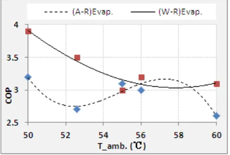
For air-conditioning unit without any modification, Figure (13) shows comparison between COP of (A-R) evaporator system and (W-R) evaporator system. It has been found that COP with using (W-R) evaporator have a higher mean value than (A-R) evaporator by about (14.1%)..
[image:9.595.312.554.355.528.2]Figure 13. Effect of ambient temperature on COP of system without any modifications
Figure (14) shows the effect of increasing outside ambient temperature on system COP with (A-R) evaporator. The figure shows comparison between COP of system without modification and system with spray water (SW). The COP of (W-R) evaporator is found to be more than the COP of (A-R) evaporator by about (102.1%) due to the high heat capacity
of water.
Figure 14. Effect of ambient temperature on COP of system with (SW) and system without modifications
[image:9.595.60.296.495.654.2] [image:9.595.313.550.562.732.2]Figure 16. Effect of ambient temperature on system COP with and without modifications
For (HE) modification, it seems that the COP has been enhanced only for (W-R) evaporator, and it has a very little effect on (A-R) evaporator, as shown in Figure (15).
Figure (16) shows comparison between COP and (Tamb.)
for all type of modifications. Using (SW) has been found as the best type of modifications with an increase in COP of about (44.5%), as a compared to system without any modification. For (Pad) modification, there is an obvious drop in system COP with increase (Tamb.) due to wet pad
secondary effect that reduces air stream. It has been found that this modification produce an increase in COP of about (20.1%) as compared to system without modification. The (VN) modification raises the effect on condenser air stream velocity. This modification has been found to produce an increase in COP of about (32.3%) as compared to system without modification.
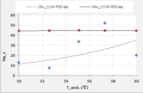
Figure 17. Effect of ambient temperature on evaporator refrigerant Nusselt number for system without modifications
Figure (17) shows effect of ambient temperature on refrigerant Nusselt number of both (A-R) and (W-R) evaporators for system without modification. The Nusselt number of (W-R) evaporator is found to be approximately constant.
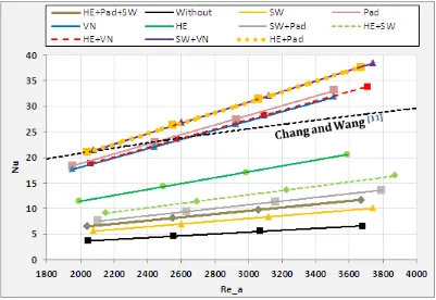
The criteria for predicting the heat transfer coefficient were the best match between the measured experimental data and the one calculated by the (EES) program. The results of the calculation are presented in Fig.(18). A Nusselt number correlation equation has been developed for each modification type by selecting the value of the Nusselt number that causes the result of the (EES) Program to fit best the experimental data at each Reynolds number. All the data necessary to run the computer program are known, except for the expression of the Nusselt number. This method for the calculating the Nusselt number was used by Coutier and Farber[10] to develop a new empirical equation for the
volumetric heat coefficient. Figure (18) shows predicted condenser air-side Nusselt number as a function of air Reynolds number. The results show that using (HE+Pad) and (SW+VN) modifications produce the highest condenser Nusselt number with an increase of about (4.7) times that of system without modifications. The predicted Nusselt number correlations have been compared with the correlation developed by Chang and Wang [11]. To the best of author’s
[image:10.595.58.295.566.720.2]Figure 18. Predicted air side Nusselt number of system with and without modification
[image:11.595.104.505.76.352.2]The predicted correlations for system with and without modifications are shown in Table (1):
Table 1. Predicted Nusselt number correlations of condenser Modification Type Predicted Correlation
Without Nu = 0.0018Re0.9996
SW Nu = 0.0027Re1
Pad Nu = 0.0094Re0.9999
VN Nu = 0.009Re1.0002
HE Nu = 0.0057Re1.001
SW+Pad Nu = 0.0036Re1
SW+VN Nu = 0.0103Re0.9997
HE+SW Nu = 0.0042Re0.9997
HE+Pad Nu = 0.0102Re1.0002
HE+VN Nu = 0.0091Re0.9999
HE+Pad+SW Nu = 0.0032Re0.9999
4. Benefit-Cost Analysis
The cost-benefit analysis has been conducted for split system air-conditioner. This product class represents a majority of equipment sales in Iraq. The Payback Period for the air-conditioning system was calculated based on the following equation;
Payback Period (in years), PP =∆OC−∆(RC+SC)∆PC+∆IC (1) Where,
∆PC = increase in Purchase Cost from base unit to the modified unit.
∆IC = increase in Installation Cost from base unit to the modified unit.
∆OC = decrease in Operating Cost from base unit to the modified unit.
∆RC = increase in Repair Cost from base unit to the modified unit.
RC = [1/2 equipment price] / equipment Life Time.
∆SC = increase in Service Cost from base unit to the modified unit.
The equipment Life Time (LT) is assumed to be (15 year). The annual Operating Cost can be calculated by the following equation;
OC = (ER). (EC). (OH). (ET) (2) Where,
ER = Electricity Rate ( $/kW.h).
The average electricity rate for Iraq was assumed to be (0.1 $/kW.h).
EC = Air-conditioner Energy Consumption ( kW). OH = annual Operating Hours of the air-conditioner. ET = Electricity Tariff (assumed to increase 2% every year). The air-conditioner is assumed to operate (10 h) daily; therefore, the average annual operating hours were determined to be (3650 hours).
[image:11.595.56.298.428.606.2]LCC = PC + ∑ OC𝑡𝑡 (1+DR)𝑡𝑡 LT
𝑡𝑡=1 (3) Where;
t = time (in years), from base case. DR = Discount rate (assumed to be 5%).
Total net benefits are calculated using Net Present value (NPV);
NPV = TS - TC .(4) Where;
TS = Total Saving in operating cost.
TC = Total Cost of equipment’s (with installation). The Benefit-Cost ratio (B/C) =TSTC (5)
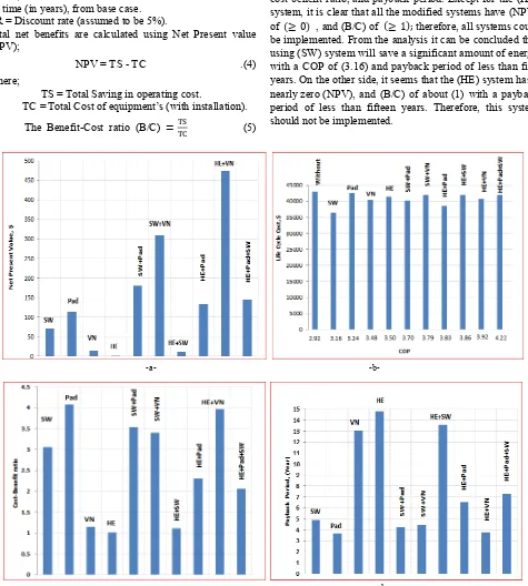
Figure (19) shows the results of the cost-benefit analysis for all systems in terms of life cycle cost, net present value, cost-benefit ratio, and payback period. Except for the (HE) system, it is clear that all the modified systems have (NPV) of (≥ 0) , and (B/C) of (≥ 1); therefore, all systems could be implemented. From the analysis it can be concluded that using (SW) system will save a significant amount of energy with a COP of (3.16) and payback period of less than five years. On the other side, it seems that the (HE) system has a nearly zero (NPV), and (B/C) of about (1) with a payback period of less than fifteen years. Therefore, this system should not be implemented.
-a- -b-
-c- -d-
[image:12.595.68.543.108.636.2]5. Conclusions
Within the limitations of materials and experimental results obtained in this work, the main conclusions may be summarized by as follows;
In general, at high ambient temperature, all types of modifications for enhancing condenser performance have been found to produce an obvious drop in outlet fluid temperature from evaporator. However, as compared to system without modifications, the (SW) modification has been found as the best one with a decrease in outlet air temperature from (A-R) evaporator of (30.3 %), and (23.6%) decrease in outlet water temperature for (W-R) evaporator. Ten new Nusselt number correlations have been predicted for each type of modifications under investigation to provide the best matching between the gathered experimental data with the result of Engineering Equation solver (EES) software. As far as known, no available Nusselt number correlations in the open literatures for air-cooled condenser under various evaporative cooling methods and subjected to high ambient temperature at the same time. The (SW) modification is found to produce an increase in system COP of about (44.5 %) for (A-R) evaporator and (102.1%) for (W-R) evaporator, as compared to system without modifications. For (SW), it is found that the consumed work of the compressor has been reduced about (75.1%) as compared to system without modification. However, (HE+Pad) modification has been found as the best method for improving air side Nusselt number of condenser with an increase of about (4.7) times that of system without modifications.
Cost benefit analysis in terms of life cycle cost, net present value, cost-benefit ratio, and payback period have been conducted. From the analysis, it can be conducted that using (SW) system will save a significant amount of energy with a payback period of less than five years. On the other side, it seems that the (HE) system should not be implemented.
The recommendation use of (SW) modification with air-cooled condensers subjected to high ambient temperature, and the predicted Nusselt number correlation related to it, will add to local knowledge a significant mean for enhancing the cooling capacity and reducing the power consumption at the same time.
Acknowledgements
The authorsgratefully acknowledge the support of Dr. Ali H. Tarrad during the construction of (W-R) evaporator and for sharing his valuable field experience.
Symbols
(A-R)evap. : Air-Refrigerant evaporator
COP : Coefficient Of Performance EES : Engineering Equation Solver HE : Heat Exchanger
Nu : Nusselt number
P : Pressure
QH : Rate of heat transfer from condenser
QL : Rate of heat transfer to evaporator
Re : Reynolds number SW : Spray Water
Tamb. : Ambient temperature
(Ta o)evap. : Outlet air temperature from evaporator
(Tw o)evap. : Outlet water temperature from evaporator
VN : Vapor Nozzle
(W-R)evap. : Water-Refrigerant evaporator
REFERENCES
[1] Dossat, R.J., Principal of Refrigeration, Prentice Hall, New Jersey, (1991).
[2] Payne, W. V. and Domanski, P. A., "A Comparison of an R22 and an R410A Air Conditioner Operating at High Ambient Temperatures", International Refrigeration and Air Conditioning Conference Proceedings, July 16-19, West Lafayette, (2002).
[3] Michalis Gr. Vrachopoulos, Andronikos E. Filios, Georgios T. Kotsiovelos, Eleftherios D. Kravvaritis “Incorporated evaporative condenser “,Applied Thermal Engineering, 27 (2007) 823–828 .
[4] Hajidavalloo E., H. Eghtedari “Performance improvement of air-cooled refrigeration system by using evaporatively cooled air condenser”, International Journal of Refrigeration, 33 (2010) 982–988.
[5] Tissot, J, P. Boulet, F. Trinquet, L. Fournasion, H. Macchi-Tejeda “Air cooling by evaporating droplets in the upward flow of a condenser” International Journal of Thermal Science 50 (2011) 2122-2131.
[6] Boulet P., J. Tissot , F. Trinquet , L. Fournaison , “Enhancement of heat exchanges on a condenser using an air
flow containing water droplets”, Applied Thermal Engineering 50 (2013) 1164-1173.
[7] Wen, M. , Ho, C. , Jang, K. , Yeh, C. , “ Experimental study on the evaporative cooling of an air-cooled condenser with humidifying air”, Heat Mass Transfer, Springer, vol.50, (2014), 225-233.
[8] Klein, S.A., EES – Engineering Equation Solver: user’s manual for Microsoft windows operating system, version 8.609. F-Chart Software, Madison, WI, USA: 2009.
[9] Moffat, R.J. Using uncertainly analysis in the planning of an experiment. J Fluids Eng 107:173-178, (1985).
[10] Coutier, J.P. and E.A. Farber, “Designing Rock Beds as Storage Units for Solar Air Systems Using an Optimized Method Based on Numerical Model”, Proceeding of I.S.E.S. Congress, Brighton, England, 23-28 Aug. 1981.
[11] Chang, Y., and C. Wang, “ A generalized heat transfer correlation for louver fin geometry”, International Journal of Heat Transfer, 40 (3) (1997) 533-544.