International Journal of Emerging Technology and Advanced Engineering
Website: www.ijetae.com (ISSN 2250-2459, Volume 2, Issue 8, August 2012)230
Harmonic Mitigation using Shunt Active Filter at Utility end in
grid connected to Renewable Source of Energy
Chandani. M. Chovatia
1, Prof. Narayan P Gupta
2, Prof. Preeti N Gupta
31,3 Department of Electrical and Electronics, OCT, Bhopal, Madhya Pradesh 2Department of Electrical and Electronics, OIST, Bhopal, Madhya Pradesh
Abstract — This paper describes the methodology of improving power quality at load end in a grid system connected with renewable source of energy for power generation. Photovoltaic cell generates electric power directly from solar energy. Solar energy based Photovoltaic cells are upcoming energy source with higher efficiency. Solar energy being naturally available in abundance and non- polluting is one of the most promising sources. Causes of power quality problems like sag swell distortion in waveform harmonics reactive power generation has affected both grid as well as utility sectors. Active Power filter are powerful tool for mitigation of harmonics. Shunt active filter with VSI topology is a simple and efficient method for harmonic elimination. Current control scheme proposed for SAPF is synchronous reference frame theory which give results within IEEE 519 range.
Keywords— Inverter, PV cells, Power quality, Shunt active Filter, Synchronous Reference Frame Theory.
I. INTRODUCTION
This paper presented here shows unique and effective methodology for planning a grid connected to renewable source of energy as solar energy and Harmonic Mitigation in system using Active Filter on utility side. Solar power is harnessed through PV panels and harmonic distortion is filtered using Shunt Active filter.
Age of fossil fuel as source of energy is constantly getting extinct. Demand of fuel and energy is exponentially rising with time. At the same time energy cost is also continuously increasing. To overcome these critical situations we can use renewable resources at our disposal from which energy can be tapped. Photovolataic cells convert solar energy to direct electric energy. Other virtues of solar energy are:
1. It requires less time to install and start up new unit for generation.
2. It has no rotating parts, hence no noise, no
maintenance and long life with less maintenance. 3. Solar energy is abundantly available on earth.
4. Problem of low efficiency and higher initial cost can be overcome by advance technology solar PV panel.
5. This energy source is non-polluting and available continuously free of cost. [9]
It is anticipated that Photovoltaic system will be major source of energy fulfilling global energy needs. Photovoltaic system has been increasingly used in medium sized grid with domestic utilities. PV panels are connected in series and parallel to generate usable amount of voltage and current. By series connection voltage level can be built up and by parallel connection current density can be increased. In addition to that Converter configuration should be efficient and cost effective.
There are many topologies available for DC/DC step up and DC/AC conversion. For maximum power transfer DC Voltage is stepped up. Boost converter, cuk converter cascading convertor topology. Boost convertor is more preferable due to less no of devices and simple control. Inverters connected to output of dc/dc converter which incorporated a Maximum Power Point Tracker (MPPT) which continuously adjusts the load impedance to provide maximum power from PV panels.
Sinusoidal waveform of AC voltage is highly distorted by current due to non linear load at common point of coupling (PCC). Due to this other load on same grid systems are affected. This creates unbalancing effect on transmission and generation side. Active filters are the solutions to these problems of unbalancing, harmonics and reactive power.
International Journal of Emerging Technology and Advanced Engineering
Website: www.ijetae.com (ISSN 2250-2459, Volume 2, Issue 8, August 2012)231
[image:2.612.52.283.180.326.2]Grid connected to Solar panels with inverter and active power filter for compensating harmonic current of non linear load is shown in fig.1
Fig. 1. PV system connected to grid with non linear load and Active Filter.
II.PVPANELS
Solar cell is basically a photovoltaic cell form of p-n junction. It when exposed to sunlight absorbs some energy greater than band-gap. This creates some hole-electron pairs proportional to incident radiations. These carriers are affected by internal electric fields of p-n junction and forms photo current proportional to solar insolation. PV cells have non linear characteristics which vary with radiation intensity and temperature.
PV cells produces less than 3W at 0.5 to 0.6 Volts, so cells are connected in series to produce enough power.[6] The terminal equation for the current and voltage of the array of PV panels are given as under:[6]
(1)
(2)
(3)
(4)
Ip = Light generated current
Vpv = Terminal voltage of the cell
ID = Diode current
Io = saturation current
Ish = shunt current
q = electron charge k = Boltzmann constant
T = Temperature Rs = Series Resistance
Rsh = shunt Resistance
III. BOOST CONVERTER AND INVERTER
Boost converter increases voltage level for inverter and control MPPT. Output voltage of boost converter is higher than input voltage. Input current is same as inductor current and hence it is not discontinuous as buck convertor and hence input filter requirements are relaxed in boost convertor. If solar panels of high rating are implemented then requirement of boost converter can also be relaxed and switching loss in converter can be saved.
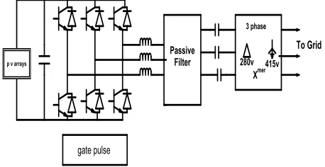
PV Panels generate DC Voltage and to connect panels to grid DC power has to be converted to AC Power. We require inverter to convert DC to sinusoidal AC before connecting to grid. Output voltage and frequency should be same as that of grid voltage and frequency. Many inverter topologies are available. In proposed scheme PWM (pulse width modulated) Voltage Source Inverter is selected d-q theory with phase. Output of the Inverter is near to Sinusoidal. 6 switches are used and its switching is controlled by discrete PWM signals. Electrical diagram for inverter is shown in Fig. 2. [7]
Fig. 2. PWM 3 phase inverter with passive filter
IV. ACTIVE FILTERS
[image:2.612.330.559.427.545.2]International Journal of Emerging Technology and Advanced Engineering
Website: www.ijetae.com (ISSN 2250-2459, Volume 2, Issue 8, August 2012)232
There are several topologies are considered to meet IEEE 519 harmonics standards at plant-utility PCC interface. Shunt active filter, series active filter, hybrid active filter with CSI and VSI inverter topologies are available. These filters are sized based on how much harmonic current is to be filtered. The filter consists of a VSI or CSI with a special electronic controller which injects harmonic current on to the system 1800 out of phase to the system harmonics. This results in a cancelling effect of the harmonics. For example if the non linear load creates 100 amps of 5th harmonic current and the active filter produced 75 Amps of 5th harmonic current, the amount of 5th harmonic current exported to the utility grid would be 25 Amps.
Shunt active filter is cost effective for low to medium industrial load. It does not create power factor displacement problem. Supply side Inductance does not affect harmonics compensation capability of active filter system. It requires simple current control implementation. It provides immunity against ambient harmonic load. In active filter protection and sequencing is relatively easy and does not require expensive isolation and switchgear. Shunt Active filters are scalable for higher KVA loads by paralleling units [2]
A. Shunt Active Filter
Shunt active filter is based on the principle of injection of load harmonic current and is characterized by non sinusoidal current reference tracking. Shunt harmonic filter requires suitable current controller for extraction of load harmonic current. [1] Proposed model of Shunt Active filter includes switching ripple filter of rating which filters current. The shunt Active filter constitutes of IGBT inverter with switching frequency of 20k Hz and rated current 200A. Active filter has output voltage Vp = 380 V and
current rating of Ip = 170 Amp. DC bus voltage of Shunt
Active filter is Vdc = 620 for nominal supply voltage of
415V. The dc bus capacitance is 1.5mF. Inverter output filter inductance is Lf = 350μH.
[image:3.612.326.556.137.332.2]In Proposed model of Shunt Active filter, shown in Fig.3 load harmonic current is injected with 1800 phase shift. Synchronous reference frame theory is implemented for controlling and extraction of load harmonic current and generating pulse for inverter.
Fig. 3. Shunt Active Filter connected to non linear load
B. Synchronous Reference Frame Theory
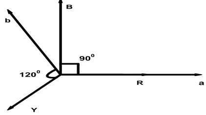
In this paper synchronous Reference frame theory based d-q model for SAPF is discussed. Instantaneous voltage and current in three phase circuit it is mathematically expressed in space vector form. [1] These three vectors R, Y, B are displaced by an angle of 1200 from each other is shown in fig.4.
Fig. 4. Vector representation of synchronous reference frame
[image:3.612.339.550.454.572.2]International Journal of Emerging Technology and Advanced Engineering
Website: www.ijetae.com (ISSN 2250-2459, Volume 2, Issue 8, August 2012)233
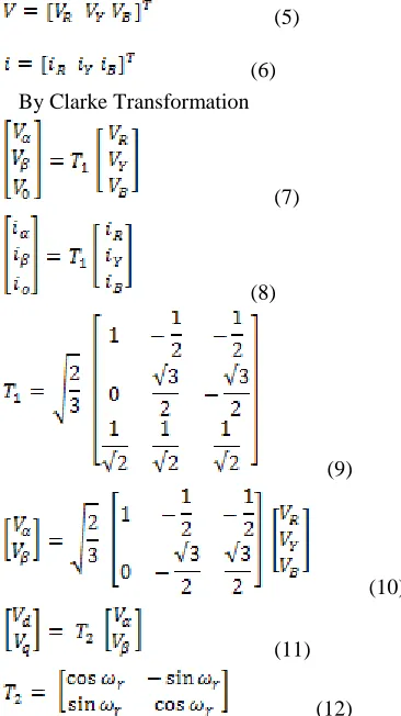
(5)
(6)
By Clarke Transformation
(7)
(8)
(9)
(10)
(11)
(12)
In three phases balanced system neutral current is zero, and zero sequence current does not exist. Voltage and currents in α and β reference frame is express as shown in equation. The Voltage in α and β reference frame is further transform in rotating reference frame with ωr as angular
velocity in d-q reference frame. Transformation from α, β to d-q reference frame can be similarly obtained. Unit vector generation for this transformation is generated by step down grid voltage.
(13)
(14)
[image:4.612.47.230.136.462.2]This control scheme shown in Fig.5 consists of inner current control loop and outer voltage control loop. The PI controller of the voltage control loop gives a current command required to maintain the DC bus voltage to set value. This is added to the AC component of d axis of the load current. This gives the current reference for d axis. The reference for q axis is obtained after the orientation of load current.
Fig. 5. Block diagram of closed loop current control scheme using synchronous reference frame theory
V.MAT LAB SIMULATION AND WAVEFORMS:
Matlab is very powerful tool for the simulation. Here simulation of Shunt Active filter in Matlab is shown in Fig.6. Control circuit for active filter is shown in Fig.7.
[image:4.612.323.565.312.440.2]International Journal of Emerging Technology and Advanced Engineering
Website: www.ijetae.com (ISSN 2250-2459, Volume 2, Issue 8, August 2012)234
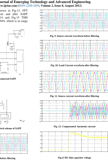
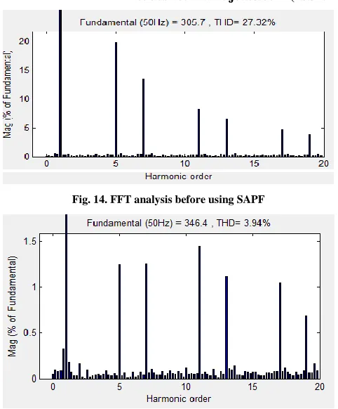
[image:5.612.196.555.106.643.2]DC link capacitor voltage is shown in Fig.13. FFT analysis for THD reduction before and after SAPF implementation is shown in Fig.14 and Fig.15 THD reduction is seen from 27.32% to 3.94% which is in range of IEEE 519 standards
Fig. 6. Simulink model of Grid connected SAPF
Fig. 7. Simulink model of current control scheme of SAPF
[image:5.612.54.280.199.352.2]Fig. 8. Load current waveform before filtering
Fig. 9. Source current waveform before filtering
Fig. 10. Load Current waveform after filtering
Fig. 11. Source current waveform after filtering
Fig. 12. Compensated harmonic current
[image:5.612.53.280.212.494.2]International Journal of Emerging Technology and Advanced Engineering
Website: www.ijetae.com (ISSN 2250-2459, Volume 2, Issue 8, August 2012) [image:6.612.48.289.128.419.2]235
Fig. 14. FFT analysis before using SAPF
Fig. 15. FFT analysis after using SAPF
VI. CONCLUSION
PV panels connected in series and parallel which give higher voltage and current level. This DC power is converted to AC using inverter. Inverter is control to feed active power to the grid using discrete PWM signals. There is harmonic injection in the grid due to non linear load on utility side. To mitigate this harmonics to IEEE 915 standards Shunt active filter is proposed and connected to load end.
Active filters operation rating and control is briefly analyzed. Important terms like switching frequency, ripple suppression dc bus voltage are addressed to meet systems performance objective. Supply current harmonics is 27.32% without active filter, which is improved to 3.94% with active filter operating.
REFERENCES
[1] S.Bhattacharya, D.M. Divan, “Active Filter Solutions For Utility
Interface of Industrial Loads”, IEEE Cont on Power Electronics Drives G- Energy Systems For Indiatial Growth (PEDES), pp 1078-1084, Jan 1996, New Delhi, India.
[2] S Bhattacharya, T. M. frank, D.M. Divan, “Active Filter
Implementation” IEEE Industry Application Magazine, September 1998.
[3] K. Vinoth Kumar, G. Surendar, M.P. Selvan, “Performance
Comparison of Shunt Active Filter and Hybrid Active Filter,” XXXII National Systems Conference, December 2008.
[4] T. Narongrit, K-L. Areerak* and K-N. Areerak,” The Comparison
Study of Current Control Techniques for Active Power Filters”, World Academy of Science, Engineering and Technology, June 2011.
[5] N. P. Gupta, P. N. Gupta, Dr. D. Masand, ”Performance Evaluation
of Hybrid Active Filter” International Conference On
Communication System and Network Technologies, June 2012
[6] R. M. Hudson, M.R. Behnke, R.West, Jerry Ginn, “Design
Considerations for Three Phase Grid connected Photo Voltaic Inverters” IEEE 1998.
[7] Jawad Faiz, Ghazanfar Shahgholian,“Modeling and Simulation of
Three Phase Inverter with rectifier type nonlinear Loads”, Armenian Journal of Physics, September 2009.
[8] Salem Rahmani, Kamal Al-Haddad, Farhat Fnaiech, “A New PWM
Control Technique Applied to Three Phase Shunt Hybrid Power Filter”, IEEE 2002.
[9] S. P. Chowdhury, “Mathematical Modeling and Performance