International Journal of Emerging Technology and Advanced Engineering
Website: www.ijetae.com (ISSN 2250-2459,ISO 9001:2008 Certified Journal, Volume 3, Issue 1, January 2013)
128
Productivity Improvement of Bucket Elevator by Modified
Design
Snehal Patel
1, Sumant Patel
2, Jigar Patel
31,3
Research scholar, 2Assistant professor,U. V. Patel, engineering college, Ganpat University
Abstract—These are powered equipment for conveying bulk materials in a vertical or steep inclined path, consisting of an endless belt, or chain/s to which metallic buckets are fixed. With the flexible belt/chain, the buckets move unidirectionally within a casing and collect bulk materials at bottom end of the equipment and deliver it at the top end.
A range of different research methods have been used to determine the productivity improvement of elevator. The present study shows the productivity improvement of elevator for granular materials by changing in parameter and structure affecting the efficiency of elevator.
Current work deals with the design and analysis of elevator for conveying granular materials at 2 tonnes/hr output and lifting height 12m. Modeling of different components of bucket elevator has been done using 3d Solid Modeling software based upon the dimensions obtained from analytical design. The new modified design of the bucket elevator is proposed and validated using CAE tools which are well within the safe limit.
Keywords— Bucket elevator, Material handling equipment, CAE tools, Bucket
I. INTRODUCTION
A bucket elevator, also called a grain leg, is a mechanism for hauling flow able bulk materials (most often grain or fertilizer) vertically. The bucket elevator is probably the oldest known form of conveyor, Its history can be traced back to the days of Babylon where wicker baskets lined with a natural pitch and fastened to ropes operating over wooden sheaves turned by slaves, were used for the elevating of water into irrigation ditches.
The Concept of the elevator has been around for many years. Variations that have changed to the elevator are its method of manufacture and types of materials used.
As new materials are developed and quality materials become more readily available, then changes in design have been made to adapt to these materials. New technology has improved both design and manufacturing procedures. Computer technology has helped reduce design time, reduce rework and understanding the behaviour of materials under different loadings. New technologies in manufacture have reduced manufacturing time, costs, weight and increased tolerances.
These changes have allowed increase discharge height and greater capacities to be obtained.
An elevator is ideally used where the product needs to be elevated and consume only a small amount of ground area. Conveyed products are mostly granular solids, which range from powders to rocks. Limitations depend on how easily product can be loaded into and discharged from the bucket. Large granular products create difficulty loading and sticky products discharging.[1]
For products that are fragile and easily crushed, slower conveyance speeds are used. It consist of
1. Bucket to contain the material
2. A belt to carry the buckets and transmit the pulley 3. Means to drive the belt
4. Accessories for loading the buckets or picking up the material, for receiving the discharged material, for maintaining the belt tension and for enclosing and protecting the elevator.
International Journal of Emerging Technology and Advanced Engineering
Website: www.ijetae.com (ISSN 2250-2459,ISO 9001:2008 Certified Journal, Volume 3, Issue 1, January 2013)
[image:2.612.108.249.144.428.2]129
Fig 1 Bucket Elevator[2]
A bucket elevator can elevate a variety of bulk materials from light to heavy and from fine to large lumps. A centrifugal discharge elevator may be vertical or inclined. Vertical elevators depend entirely on the action of centrifugal force to get the material into the discharge chute and must be run at speeds relatively high. Inclined elevators with buckets spaced apart or set close together may have the discharge chute set partly under the head pulley. Since they don't depend entirely on the centrifugal force to put the material into the chute, the speed may be relatively lower.
Nearly all centrifugal discharge elevators have spaced buckets with rounded bottoms. They pick their loads from a boot, a pit, or a pile of material at the foot pulley. The buckets can be also triangular in cross section and set close to on the belt with little or no clearance between them. This is a continuous bucket elevator. Its main use is to carry difficult material at slow speed.
Early bucket elevators used a flat chain with small, steel buckets attached every few inches. Current construction uses a rubber belt with plastic buckets. Pulleys several feet in diameter are used at the top and bottom. The top pulley is driven by an electric motor.
The bucket elevator is the enabling technology that permitted the construction of grain elevators. A diverter at the top of the elevator allows the grain to be sent to the chosen bin. A similar device with flat steps is occasionally used as an elevator for humans, e.g., for employees in parking garages. (This sort of elevator is generally considered too dangerous to allow use by the public) [2]
II. DESIGN OF BUCKET ELEVATOR
Power
P = (1.15+K2. K3.V)From designdata bookwe find value of K2, K3 and V for given capacity. After the apply the value of Q and H we find the power is equal to 0.8068 Kw.[3]
D = 2 *
N =
T =
From above three equations we find the torque is 102.724 N.m. For the shaft we choose the C40 or En8 material. Shear stress for C40 or En8 material = 230 N/mm2.[4]
d3 =
International Journal of Emerging Technology and Advanced Engineering
Website: www.ijetae.com (ISSN 2250-2459,ISO 9001:2008 Certified Journal, Volume 3, Issue 1, January 2013)
130
III. ANALYSIS OF BUCKET ELEVATOR
A. FEA Analysis of Head Pulley
[image:3.612.324.565.149.286.2]Applying the Loading Condition:
Fig 2.1 Loading condition of head pulley shaft
Apply the belt load on the shaft and head pulley. Directions of the all load are downward. For the rotation part apply the rotation velocity 76 rpm at direction of the rotation of the shaft. Apply the frictionless support for the bearing.
Von Mises Stress:
Fig 2.2 Von mises stress of head pulley
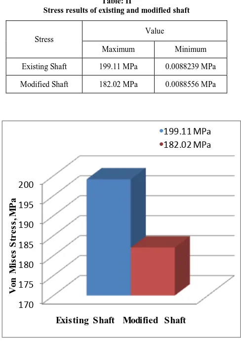
From the analysis we get the maximum stress is 199.11 MPa. Maximum stress occurs at the shaft which is near the head pulley. Minimum stress occurs at end shaft and head pulley.
[image:3.612.49.289.185.354.2]Total Deformation:
Fig 2.3 Total Deformation of head pulley shaft
From the analysis we get the maximum deformation is 2.2381 mm. Maximum deformation occurs at right end of the shaft. From right to left deformation is reduced. Minimum deformation occurs at left end of shaft and head pulley.
B. Modification
There are some reasons for modification
1)If the break occurs at the inner edge of the pulley, you might consider fretting corrosion.
2)If the pulley is not tight enough on the shaft, micro movement of the pulley on the shaft can cause fretting corrosion which creates stress risers and finally a complete failure of the shaft from fatigue. This can happen unbelievable quickly.
3)Bucket elevator tail pulley shaft keeps failing. the shaft is made of mild steel.it is always break closest to the bore of the pulley.
The change of material from EN-8 to EN-24 gives a marginal reduction in stress due to the change of property of the material. [8].EN-24 has more fretting corrosion resistance than EN-8 material. So, we proposed new material En 24[9, 10].
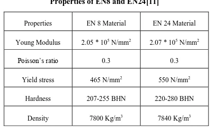
Table I
Properties of EN8 and EN24[11]
Properties EN 8 Material EN 24 Material Young Modulus 2.05 * 105 N/mm2 2.07 * 105 N/mm2
Poisson’s ratio 0.3 0.3 Yield stress 465 N/mm2 550 N/mm2
[image:3.612.48.290.453.623.2] [image:3.612.338.552.590.719.2]International Journal of Emerging Technology and Advanced Engineering
Website: www.ijetae.com (ISSN 2250-2459,ISO 9001:2008 Certified Journal, Volume 3, Issue 1, January 2013)
131
C. FEA Analysis of Head Pulley After Modification
Von Mises Stress:
Fig 2.4 Von mises stress of head pulley
From the analysis we get the maximum stress is 182.02 MPa. Maximum stress occur at the shaft which is near the head pulley. Minimum stress occurs at end shaft and head pulley.
Total Deformation:
Fig 2.5 Total Deformation of head pulley shaft
From the analysis we get the maximum deformation is 1.9412 mm. Maximum deformation occurs at right end of the shaft. From right to left deformation is reduced. Minimum deformation occurs at left end of shaft and head pulley.
IV. RESULT AND DISCUSSION
[image:4.612.48.291.165.321.2]A. Stress (Von Misses stress) comparison
Table: II
Stress results of existing and modified shaft
Stress
Value
Maximum Minimum
Existing Shaft 199.11 MPa 0.0088239 MPa
Modified Shaft 182.02 MPa 0.0088556 MPa
170 175 180 185 190 195 200
V
o
n
M
is
e
s
S
tr
e
s
s
, M
P
a
Existing Shaft Modified Shaft
•
199.11 MPa•
182.02 MPa [image:4.612.326.570.174.524.2] [image:4.612.54.285.406.553.2]B. Displacement of head pulley
Table: III
Displacement results of existing and modified shaft
Displacement
Value
Maximum Minimum
Existing Shaft 2.2381 mm 0.0003841 mm
International Journal of Emerging Technology and Advanced Engineering
Website: www.ijetae.com (ISSN 2250-2459,ISO 9001:2008 Certified Journal, Volume 3, Issue 1, January 2013)
132
C. Factor of Safety comparison
For existing design F.S = design stress / induced stress
= 465 / 199.11
= 2.3
For modified design F.S = design stress / induced stress
= 550 / 182.02
= 3.0
Table: IV
FOS of existing and modified shaft
Shaft Factor of Safety
Existing Shaft 2.3
Modified Shaft 3.0
V. CONCLUSION
A general design of bucket elevator has been proposed. Static structural analysis for different components of bucket elevator has been done with FEA tools under standard operating conditions. Bucket elevator mainly fails due to breaking occurs at the inner edge of the pulley, it consider as fretting corrosion. So new material EN24 has been suggested for the shaft. From the analysis, it can be seen that for modified design has higher FOS than existing design.
The aim of this dissertation is to improve the design of bucket elevator. The obtained modified design serves the purpose of design. The analysis results for existing and modified design both are well within the safe limit under standard operating conditions.
REFERENCES
[1] Material Handling Equipment by Rudenko, MIR Publishers.
[2] Bulk Solids Handling: An Introduction to the Practice and
Technology by C. R.Woodcock, J. S. Mason
[3] PSG Design data book , pages 9.24-9.26
[4] Belt conveyor elevator design by Mike Sondalin, Second Edition,
International Journal of Emerging Technology and Advanced Engineering
Website: www.ijetae.com (ISSN 2250-2459,ISO 9001:2008 Certified Journal, Volume 3, Issue 1, January 2013)
133
[5] IS code 6833-1973, Reaffirmed 2011, ―Specification for buckets for
bucket elevators‖
[6] IS 7054-1973, Reaffirmed 2011, ―Specification for casing for bucket
elevators‖
[7] IS code 6832-1985, Reaffirmed 2010, ―Specification for fixing
screw and fixing washers for buckets for bucket elevators‖
[8] S.N.Vijayan*, M.Makeshkumar (2012). ―Material Specific Product
Design Analysis for Conditional Failures – A Case Study.‖ International Journal of Engineering Science and Technology: Vol-4,pages 976-984
[9] Optimization of burnishing parameters and determination of select
surface characteristics in engineering materials P Ravindra babu, K Ankamma, T Siva Prasad ,Vol. 37, Part 4, August 2012, pp. 503– 520. Indian Academy of Sciences
[10] R Ramesh, R. Gnanamoorthy (2007). ―Artificial Neural Network
Prediction of fretting wear behavior of structural steel,EN 24 against bearing steel EN 31.‖ journal of materials engineering and performance 6, Vol 16,Pages 703-709
![Fig 1 Bucket Elevator[2]](https://thumb-us.123doks.com/thumbv2/123dok_us/8732722.887492/2.612.108.249.144.428/fig-bucket-elevator.webp)