International Journal of Emerging Technology and Advanced Engineering
Website: www.ijetae.com (ISSN 2250-2459, ISO 9001:2008 Certified Journal, Volume 3, Issue 1, January 2013)
236
Analysis of NACA 2412 for Automobile Rear Spoiler Using
Composite Material
A. Sunanda
1,
M. Siva Nayak
2 1Asst. prof, Department of Mechanical Engg., SNIST, Ghatkesar, Hyderabad. 2Asst Prof, Mechanical Engineering Department, Rise Groups Of Institution, Ongole. Abstract-- The NACA 4digit series aerofoil shapes are
universally accepted standard designs generally used for wind turbine blades, helicopter rotor blades and car spoilers. The Design and Simulation of these complex shapes is a challenging task for the manufacturing engineers. These components need to be made of materials having high specific strength and better fatigue properties. The composites with sandwich construction fulfill the above requirements.
The main aim of the present investigation is to select the best fiber orientation for the fabrication of automotive rear spoiler. The Design FOIL software provides different shapes of aerofoil from which NACA 2412 has been selected. The spoiler is modeled using CATIA software and is analyzed for the static deflection as well as harmonic analysis has been done by using ANSYS for various orientations of the fiber. The designed model has been compared with the values obtained from the simulation values. This confirms the design feasibility and software adoptability for the design of sandwich aerofoil shapes.
Keywords-- Automobile Rear Spoiler, CATIA, Composite Material, NACA, air foil
I. INTRODUCTION
A car spoiler is a wing like accessory that is usually attached to the rear end of the cars, or normally mounted on top of a car's trunk or positioned under the front bumper. While the rear spoiler is sometimes called 'wing', the frontal car spoilers are also called 'air dam'. Car spoiler dynamically improves the external beauty of the car making the car stand out in a crowd, making it more trendy and sporty. In automobile parlance, a spoiler is an aerodynamic device that is attached to an automobile. The intended function of this device is to 'spoil' unfavorable air movement across a body of vehicle of some kind in motion.
It is customary for racing and other high performance sports cars to be fitted with spoilers. Nowadays-even passenger vehicles use spoiler very commonly. To put it more succinctly, a car spoiler improves the performance of the car and even sometimes stimulates its resale value of the car.
The next area for development was to manage the airflow underneath the car; firstly this was done by using suction fans in the 1970’s, once again by Chevrolet-Chaparral.
However this car was banned as the cornering speeds reached, up to 1.7g, were thought too dangerous. This was taken on by Lotus when in 1978 the Lotus 79 had a fully shaped underbody to channel the airflow, this car was also banned. Modern day Formula One cars can now reach cornering speeds of up to 5g, even though there are very strict restrictions in the guidelines. This shows how far automotive aerodynamics have been improved.
The introduction of the car spoiler begins in the 1960s, when NASCAR automobiles still looked like what you drove on the street. In 1966, the Dodge Charger had a flatter nose and a long, sloping roofline that seemed to make the car unstable and lift at higher speeds. NASCAR was petitioned and they allowed the Dodge teams to a piece of metal about one-half to two inches high to the rear decklid. This trapped air on the decklid and created down force to stabilize the car. It did not make the Dodge a standout car, but other manufacturers did see the aerodynamic perk of adding something to the back of the car to increase down force.
II. BASIC FUNCTION OF SPOILER
The main function of a spoiler is diffusing the airflow passing over and around a moving vehicle as it passes over the vehicle. This diffusion is accomplished by increasing amounts of turbulence flowing over the shape, “spoiling “the laminar flow and providing a cushion for the laminar boundary layer often spoilers are added solely for
appearance with no thought towards practical purpose.
International Journal of Emerging Technology and Advanced Engineering
Website: www.ijetae.com (ISSN 2250-2459, ISO 9001:2008 Certified Journal, Volume 3, Issue 1, January 2013)
237
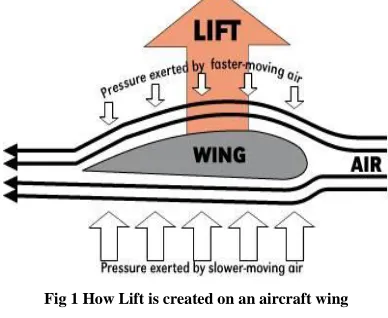
[image:2.612.361.537.145.217.2]However if the wing were turned upside down then the resultant force would be downwards, this is called down force and is useful in car design as it pushes the tires onto the road giving more grip. The diagram below illustrates the Bernoulli principle on an aircraft wing.
[image:2.612.70.264.205.364.2]Fig 1 How Lift is created on an aircraft wing
Fig.2 Air foil
Over the whole of a cars body there are many different areas of lift and down force created. When explaining drag it was said that the air molecules slowed when approaching the front grill and then accelerated over the top and sides of the car. This means that when the air flows over the bonnet of the car it will be accelerating and so at a lower pressure, therefore a lift force is felt over the bonnet. The air then meets the windscreen and this acts like a barrier, similar to the front grill and so a small down force will be created here. The air then once again accelerates to create lift over the roof of the car. For some vehicles the roof has a large surface area and so a large lift force can be created. There may also be down force created as the air flows underneath the vehicle, if there is a narrow gap between the road and the car the air is constricted and so has to accelerate, creating ’suction’ to the road surface. These forces are shown on the diagram below.
[image:2.612.78.260.364.499.2]
Fig.3 Forces created by airflow over a car body
III. BENEFITS OF CAR SPOILERS
A spoiler is a flattish, slightly curved appendage on the rear of the vehicle. Spoilers are found on racing cars and high performance sports cars. They primarily reduce the amounts of lift and drag a vehicle experiences and at higher speed the force of the wind pushes down on the spoiler adding additional traction for the tires. While most stock spoilers usually add no discernable performance, a racing spoiler that is usually larger in size and more aerodynamic can add performance- especially at higher speeds.
Apart from contributing to the external appearance of the car, the spoiler is very useful in making the car more fuel-efficient. This mechanical accessory can make the car stable on roads. Spoiler improves vehicle stability by decreasing lift or decreasing drag that may cause unpredictable handling in a car speed. Spoiler disrupts the airflow going over a moving car thereby reducing the amount of life naturally generated by the shape of the car. Spoiler accomplishes this feat by increasing the turbulence flowing over the shape 'spoiling' the laminar flow and providing a cushion for the laminar boundary layer.
Most of the time, the car spoiler is a styled piece of fiberglass, which enhances the aerodynamics of the car. Due to increase in traction a car in motion brakes, turns and accelerates with more stability. Drag increases as the speed of the car increases. It can be seen that some spoilers are effective at very low speeds often generating excessive drag while some other spoilers can work pretty well at high speeds. Some passenger cars can be seen equipped with both front and rear spoilers. Front spoilers which are found beneath the bumper are used to direct airflow away from the tires to the under body. Rear spoilers help to modify the transition in shape between the roof and the rear and the trunk and the rear. This minimizes the turbulence at the rear of the vehicle. Some rear spoilers come with a warning brake light built into the spoiler.
IV. CAR SPOILER TYPES
International Journal of Emerging Technology and Advanced Engineering
Website: www.ijetae.com (ISSN 2250-2459, ISO 9001:2008 Certified Journal, Volume 3, Issue 1, January 2013)
238
Most of the car spoilers come made of polyurethane. Spoilers are also made of lightweight steel while others of fiberglass. These lightweight spoilers are found to be extremely durable and do not crack, separate or sag.
Sometimes spoilers can be made of a combination of two or three dissimilar substances. Car spoilers made of 'high impact resin' display high density with extreme temperature resistance. They are super impact resistant. Generally, spoilers are purchased unpainted to facilitate the buyer paint it on an accurate color match with the car.
Mention should be made of the fact that most of the time a car spoiler is incorrectly confused with 'wings'. While automotive wings are devices whose intended design is to actually generate down force as air passes around them, the function of a car spoiler is to disrupt existing airflow patterns.
V. COMPOSITE MATERIALS
A composite is a structural material that consists of two or more combined constituents that are combined at a macroscopic level and are not soluble in each other. One constituent is called reinforcing phase and the one in which it is embedded is called the matrix. The reinforcing phase material may be in the form of fibers, particles, or flakes. The matrix phase materials are generally continuous. In this form, both fibers and matrix retain their physical and chemical identities, yet they produce a combination of properties that cannot be achieved with either of the constituents acting alone. In general, fibers are the principal load carrying members, while the surrounding matrix keeps them, and protects them from environmental damages due to elevated temperatures and humidity.
The composite materials have the following properties:
High specific strength
High specific stiffness
More thermal stability
More corrosion and wear resistance
High fatigue life
VI. FORMULATION OF PROBLEM AND ANALYSIS
The main aim of the present work is to investigation the better orientation of the glass fiber in the spoiler manufacturing. As composite material have tailoring properties i.e., based on the users requirement material properties of the component can be obtained by stacking the different or similar oriented fiber together.
Design of Fiber Reinforced polymer composite components require extensive study of material properties before selecting the material to be used to make the product. Design approach used for metallic materials could not be utilized for polymer composite materials, since these materials are orthotropic in nature. Design of composite materials is based on the classical laminate theory. The cumbersome mathematical solutions may be performed to estimate the tailored material properties to be estimated by software tools.
The design of the FRP components requires a definite approach with consensus of discussion depending on the functional requirements. The complex nature of failure behavior of fiber-reinforced composites makes the design approach complex. In view of developing user-friendly approaches for design of commercial FRP products the present work provides a pathway towards establishing simple methods for required class of products.
Typical Aerofoil shapes have been found in a different NACA series from that a NACA 2412 four digit model has been taken for the simulation.
In the present work the Design FOIL workshop is used to export the coordinates for geometric molding and to estimated the lift and drag coefficients. Based on the lift and drag coefficients the lift and drag forces are calculated based on the below mentioned formulae:
Lift force L= ½ ρ*V2*S*Cl
Drag force D = ½ ρ*V2*S*Cd
To avoid the laborious processes laminate design software is developed as a first experimental work.
International Journal of Emerging Technology and Advanced Engineering
Website: www.ijetae.com (ISSN 2250-2459, ISO 9001:2008 Certified Journal, Volume 3, Issue 1, January 2013)
239
Fig.4 Assembled Aerofoil Model
VII. RESULTS
[image:4.612.332.551.131.297.2]The assembled model then is imported into ANSYS. Meshing has been done using mesh option as shown in figure.
Fig.5 Meshed Model
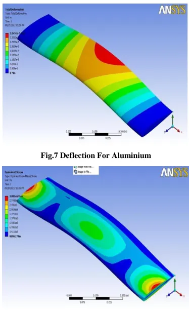
The finite element modeling and analysis is used to study the deflections and stress variation at different locations of the spoiler and also the deflection at various ends. The figure shows all the deflection stresses and harmonic Analysis at different orientations of fibers.
[image:4.612.55.251.135.266.2]Fig.6 Model in Workbench
[image:4.612.349.536.316.622.2]Results for Aluminium material
Fig.7 Deflection For Aluminium
[image:4.612.60.277.339.510.2]International Journal of Emerging Technology and Advanced Engineering
Website: www.ijetae.com (ISSN 2250-2459, ISO 9001:2008 Certified Journal, Volume 3, Issue 1, January 2013)
240
Fig.9 Frequency Vs Amplitude for aluminum Results for 00 orientation
Fig.10 Deflection at 00 orientation
Fig.11 Equivalent stress 00 orientation
Fig.12 Frequency Vs Amplitude (00)
Results for 450 orientation
Fig.13 Deflection at 45o orientation
International Journal of Emerging Technology and Advanced Engineering
Website: www.ijetae.com (ISSN 2250-2459, ISO 9001:2008 Certified Journal, Volume 3, Issue 1, January 2013)
241
Fig.15 Frequency Vs Amplitude (450)
Results for 600 orientation
Fig.16 Deflection at 60o orientation
Fig.17 Equivalent stress 600 orientation
Fig.18 Frequency Vs Amplitude (600)
Results for 900 orientation
Fig.19 Deflection at 90o orientation
International Journal of Emerging Technology and Advanced Engineering
Website: www.ijetae.com (ISSN 2250-2459, ISO 9001:2008 Certified Journal, Volume 3, Issue 1, January 2013)
242
Fig.21 Frequency Vs Amplitude (900)
VIII. CONCLUSION
1.The simulation results are that [±45o]orientation of the fiber is the best orientation for the fabrication of the spoiler.
2.[±45o]orientation of the fiber with foam gives best result when compared the same [±45o]orientation of the fiber without foam
3.The fabrication of the spoiler has been done with
sandwich construction..
4.
The theoretical calculation and the simulation results differ i.e., due to localized buckling effect in the sandwich construction.IX. SCOPE FOR FUTURE WORK
Having successfully proven that the manufacturing concept is feasible in basic engineering terms, work is currently in progress on Spoiler design and analysis. Although flat panel structures are relatively simple to
model for FEA, it is necessary to quantify the mechan
ical
properties of the bonded joints, and to represent these in the model efficiently.
In the current situation of limited resources, the
following aspects are recognized as being of
considerable importance, but must wait further
funding:
• Manufacturing of different composite materials like
Kevlar/epoxy, Boran/epoxy, Carbon/epoxy
• Selection of sandwich panel component materials
(skins and core) for ease and consistency of manufacture, performance and recycling.
• Optimization of adhesive for cure cycle and long term
properties.
• Crashworthiness testing.
• Production plant layout, process monitoring and
quality systems.
• Operational considerations (e.g. thermal, acoustic and
dynamic characteristics).
Funding and in-kind support is actively being sought
from various bodies (e.g. materials suppliers,
manufacturers and potential customers) to carry the project forward.
REFERENCES
[1 ] W.J. Cantwell et al. A comparative study of the mechanical properties of sandwich materials for nautical construction. SAMPE Jnl., 30 (4), 45-51 (1994).
[2 ] K. Lowe. Automotive steels. Engineering, Feb. 1995, 20-21.
[3 ] http://www.fibermaxcomposites.com/index.files/manufacturingtechn
iques.htm
[4 ] http://www.dreesecode.com
[5 ] http://www.en.wikipedia.com
Material Deflection
(mm)
Von-misses Stress N/mm2
Peak frequency (Hz)
foam 9.057 141.49 1400
Without