EUR 4t0S
e
COMMISSION OF THE EUROPEAN COMMUNITIES
HERA-1A, HEAT TRANSFER IN ROD ASSEMBLIES
A computer programme
for steady state thermo-hydraulic analysis of multirod fuel bundles
cooled by liquid metal under non-boiling conditions
by
R. NIJSING and W. EIFLER
1973
.@
Joint Nuclear Research Centre lspra Establishment - Italy
Technology
Joint Nuclear Research Centre Ispra Establishment - Italy
ABSTRACT
The present report provides a description of HERA-IA, a computer programme for steady state thermo-hydraulic analysis of multirod fuel bundles with liquid metal cooling. A description is given of the physical model and mathematical procedures underlying the programme. A complete listing of the programme with sample output is given as appendix.
KEYWORDS
H CODES
FUEL ELEMENT CLUSTERS HEAT TRANSFER
LIQUID METALS
MATHEMATICAL MODELS SODIUM
EQUATIONS
I
~·
3
-CONTENTS
5
1. INTRODUCTION
2. OUTLINE OF PHYSICAL MODELS AND BASIC EQUATIONS
1
7
7
3.
4.
2. 1
Hydrodynamic and thermal subchannel interactions
2.
1. 1 Assemblies of bare rods
2. 1. 2
2. 1. 3
2.2
2.3
2.4
2.4.1
2.4.2
DESCR
3. 1
3.2
3.3
CONG
ACK!'
NOMl
REFE
APPE
APP:E
10
effects
,mblies of rods provided with helical spacers
11channel coolant mass flow distribution
~channel coolant-enthalpy distribution
18,ects related to the spatial variation of fuel heat
~ration
21
i.ation of heat generation in the axial direction
ation of heat generation in the lateral direction
21
24
ON OF THE HERA-IA COMPUTER PROGRAMME
,graphic-
1:.onsiderations
EUR 4905 e
HERA-IA, HEAT TRANSFER IN ROD ASSEMBLIES - A computer programme for steady state thermo-hydraulic analysis of multirod fuel bundles cooled by liquid metal under non-boiling conditions by R. NIJSING and W. EIFLER
Commission of the European Communities
Joint Nuclear Research Centre - Ispra Establishment (Italy) Technology
Luxembourg, February 1973 - 160 Pages - 11 Figures - B.Fr.
210.-Tne present report provides a description of HERA-IA, a computer programme for steady state thermo-hydraulic analysis of multirod fuel bundles with liquid metal cooling. A description is given of the physical model and mathematical procedures underlying the programme. A complete listing of the programme with sample output is given as appendix.
EUR 4905 e
HERA-IA, HEAT TRANSFER IN ROD ASSEMBLIES - A computer programme for steady state thermo-hydraulic analysis of multirod fuel bundles cooled by liquid metal under non-boiling conditions by R. NIJSING and W. EIFLER
Commission of the European Communities
Joint Nuclear Research Centre - Ispra Establishment (Italy) Technology
Luxembourg, February 1973 - 160 Pages - 11 Figures - B.Fr.
210.-The present report provides a description of HERA-IA, a computer programme for steady state thermo-hydraulic analysis of multirod fuel bundles with liquid metal cooling. A description is given of the physical model and mathematical procedures underlying the programme. A complete listing of the programme with sample output is given as appendix.
26
5
-1.
INTRODUCTION
This report presents the HERA computer programme for steady state
ther-mohydraulic analysis of multirod fuel bundles cooled by an incompressible
fluid under non-boiling conditions. The present version 1 A of HERA
consi-ders a hexagonal fuel rod assembly cooled by sodium. It essentially applies
to bundles of bare rods and to bundles with grid type spacers. It may also be
used for bundles with helical spacers, but it is recognized that for these
geo-metries intersubchannel transport phenomena at the edge of the bundle are not
described in an entirely satisfactory way.
The HERA computer programme is based on a "lumped parameter"
ap-proach involving subdivision of the bundle flow area into a number of parallel
subchannels and characterization of the hydrodynamic and thermal conditions
/
of the coolant in each of these subchannels by_ bulk average values.
Hydrody-namic and thermal interactions between adjacent sul;>channels are described
in terms of mixing coefficients. The present version of HERA is chiefly aimed
at evaluating how intersubchannel mixing attenuates differences in subchannel
coolant temperature that arise from a lateral power gradient along the
diago-nal of the hexagonon and/or from differences in the subchannel geometry.
For arrays of bare rods both turbulent diffusion and conduction contribute
to intersubchannel mixing. In the presence of helical spacers the dominating
mechanism (lUlless for small pitch to diameter ratios, say beneath
1.
08) is
the periodic transverse flow induced by the spacer. Grids cause enhanced
tur-bulent mixing and in the edge region of the bundle, where both coolant
veloci-ties and grid flow resistance coefficients are likely to vary among
subchan-nels, they may give rise to lateral pressure gradients causing cross flow.
In the present version of HERA cross flow effects are ignored and for the
case of helical spacers intersubchannel heat transport is described in terms
of a continuous mixing model and not in terms of a doubtless more realistic
periodic mixing model.
6
-flow rates, subchannel coolant enthalpies and various derived parameters of
engineering interest. Axially averaged coolant mass flow rates result from
subchannel momentum balances over the fuel rod bundle length. In these
ba-lances account is taken of pressure drop across the fuel element, friction at
the subchannel walls, pressure drop across the grids and intersubchannel
mixing between adjacent subchannels. The axial distribution of subchannel
coolant enthalpies is found from subchannel heat balances that lead to a
sys-tem of linear first order differential equations, each made up of an axial
en-thalpy gradient term and of terms accounting for transport of heat between
adjacent subchannels and for subchannel heat input. The latter is determined
from the lateral and axial power distributions which can be matched by
analy-tical expressions.
An
outstanding feature of the HERA computer programme is that the
ma-thematical solution of the coolant enthalpy differential equation system is
ob-tained analytically via the solution of an algebraic eigenvalue problem. This
provides the homogeneous part of the solution for the subchannel coolant
en-thalpy distribution, that depends exclusively on the geometrical configuration,
the subchannel mass flow distribution and the mixing characteristics. The
power distribution characteristics have an effect only on the "particular"
so-lution. The chief part of the computation time is bound up with the solution of
the eigenvalue problem, whereas the formulation of the "particular" solution
requires very little time. As a consequence it becomes possible to obtain
results for a number of additional different power distributions, other
condi-tions remaining unvaried, with only a slight increase of computation time.
The HERA computer programme further is characterized by the
simplici-ty of the procedure for specifying input data. E. g. subchannel data
(subchan-nel sections, wetted perimeters, heated perimeters, hydraulic diameters,
characterization of subchannel interactions etc.) are not specified as input
information, but they are evaluated in the programme. This approach makes
it necessary to focus the attention on a specific rod bundle geometry. The
7
-triangular lattice in hexagonal boxes as employed in reactors of the fast
breeder type.
The following chapters present an outline of the physical models and of
the mathematical procedures underlying the programme and furnish a
des-cription of this programme. A somewhat more detailed account of the
phy-sical and mathematical aspects underlying the HERA rod bundle analysis will
be published in a separate paper{!).
2. OUTLINE OF PHYSICAL MODELS AND BASIC EQUATIONS
2. 1 Hydrodynamic and thermal subchannel interactions
2. 1. 1 Assemblies of bare rods
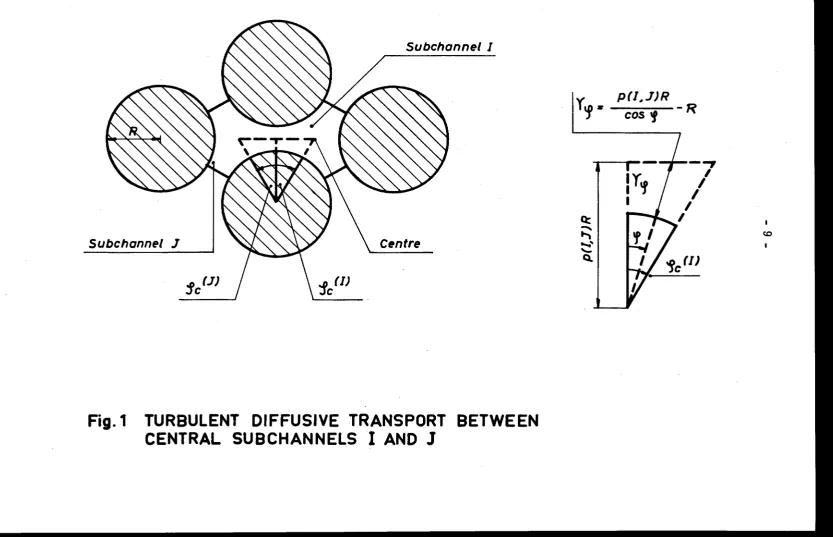
The present considerations regard intersubchannel transport of momentum
and heat in assemblies of bare parallel rods.· It is assumed that molecular
diffusion (i. e. conduction, applying to heat transport only) and turbulent
dif-fusion represent the sole mechanisms contributing to this transport process.
Subchannel mass flow rates are assumed to be invariant with axial position.
Coolant density variations are ignored. Momentum and heat mixing coefficients
a (I, J) and
f3
{I, J) characterizing transport between subchannels I and J (see
Fig. 1) are defined by:
Q
m
a(I, J)
=
dz [ p U{I)- p U{J)]
Q
(3
(I
J) - _ _
h
_ _
_
'
- dz [H(I) - H(J)]
{l)
(2)
Here Qm/dz and Qh/dz represent intersubchannel flows of momentum and
heat per unit of length whereas U(I} and H(I} denote bulk average values of
axial velocity and coolant enthalpy (the latter at a given axial position z) in
a subchannel
I.
Assuming Qm and Qh to be invariant :'ith
cp
in the interval
- cp
(J}
~cp
~cp
(I} at any
cp
value in this interval holds:
8
-Q
du
_ill
= -
2
y
e:
p
1.
m. <p
dz
q> q>
r eff. d
cp
(3)
Qh
dH
Y
l+
a)
p
1.
m.
<P- = -
2
\W
e:
-dz
cp
cp
r eff. d
cp
(4)
Here Yq> is a radial distance parameter given for the example of Fig. 1 by:
ycp
=
p(I,J).R -
R
(5)
cos
cp
where p(I,
J)
is the pitch to diameter ratio of the rods separating
subchan-nels I and
J.
The parameter r eff denotes an effective radial position
approxi-mated by:
r eff~
=
p(I,
J)
R
(6)
An
assumption must be made with regard to the circumferential position
in-side a subchannel I at which the radially averaged velocity u
1
. m.
cp
and
en-thalpy H
1
. m.
equal the subchannel bulk values U(I) ~nd H(I). The
pessimis-tic option made in the HERA programme is that this occurs at the position
cp (I) corresponding to the centroid of
I.
The (radially averaged) turbulent
C
diffusivity
e:
is expressed by:
cp
(I)
1/2
e:cp
=CEF. Y cp[wp
J
(7)
with CEF
=0.154(
2
). The following expression is employed for the ratio of
Cturbulent diffusivities for heat and momentum transfer:
[
-5
1/3 ]
"1
=l.38
l-exp(-12.410
.ANF.YFRe.Pr
)
(8)
which is a modification of the relation due to Bobkov et al. (
3)_Here .ANF
de-notes th.e ratio of turbulent diffusivities in circumferential and radial
direc-tion and YF the ratio of circumferentially averaged profile length Ycp to the
hydraulic diameter. Integrating eqs.
(3)
and (4) circumferentially in the
inter-val - q>
(J)
and
+
cp
(I) yields:
C C
+
cp
(I)
C
1
-1J
[<X
(I,
J)
=
-q,c(J)
p(I, J}R
dq,
2Y
ecp
cp
Subchannel I
Subchannel
J
Centre
'Sc(J)
Fig. 1 TURBULENT DIFFUSIVE TRANSPORT BETWEEN
CENTRAL SUBCHANNELS
I
AND
J
Yi •
p(I.,J)R
'f
cos
f
-
R
Q::
~
...
'-Q.
---,
I
I
I
I
I
I [image:9.919.66.900.52.589.2]10
-cp (I)
C
I
p(I,
J}
R
d
2Ycp(1J,e:q>+a)p
q>
{10)
- q>
(J)
C
It
is worth pointing out that the physical properties underlying the computation
of a (I,
J)
and
13
(I,
J)
are taken at the spatially averaged coolant temperature in
the fuel element.
2. 1. 2 Grid effects
The presence of grids will cause an augmentation of intensity and scale of
turbulence in the downstream region, entailing an increase of turbulent
dif-fusivity compared to that in assemblies of bare rods. In the vicinity of the
channel wall, where coolant velocities and grid flow resistance coefficients
are likely to vary from one subchannel to the other, lateral pressure
differ-ences will develop leading to intersubchannel cross flow at positions both
up-stream and downup-stream of a grid. The model in the present computer
pro-gramme considers the enhancement of turbulent diffusion to be constant over
the axial distance interval between two grids. The effect of cross flow on
in-tersubchannel heat transport is taken into consideration in an approximate
manner by introducing a grid mixing coefficient operative only at the axial
position of the grid. The grid mixing coefficient Y (I,
J)
for macroscopic
inter-actions between a subchannel I and a neighbouring subchannel
Jis defined by
a heat balance across the grid for the subchannel I:
(11)
Here the subscripts d and u denote downstream and upstream positions.
The summation in the second right hand term of eq. (11) is carried out over
11
-Z.
l.
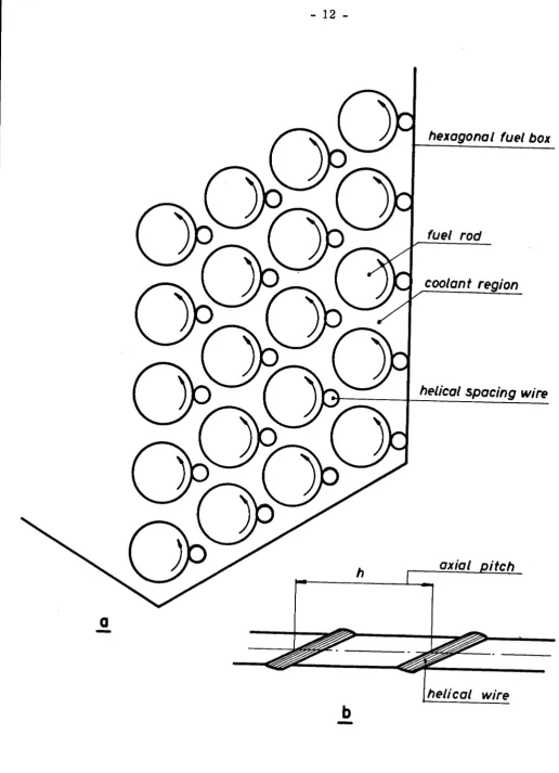
3 Assemblies_ of rods_provided with helical spacers
The configuration considered {see Fig. Z} is one in which the rods are
spaced by helical wires, all turning in the same direction. The dominating
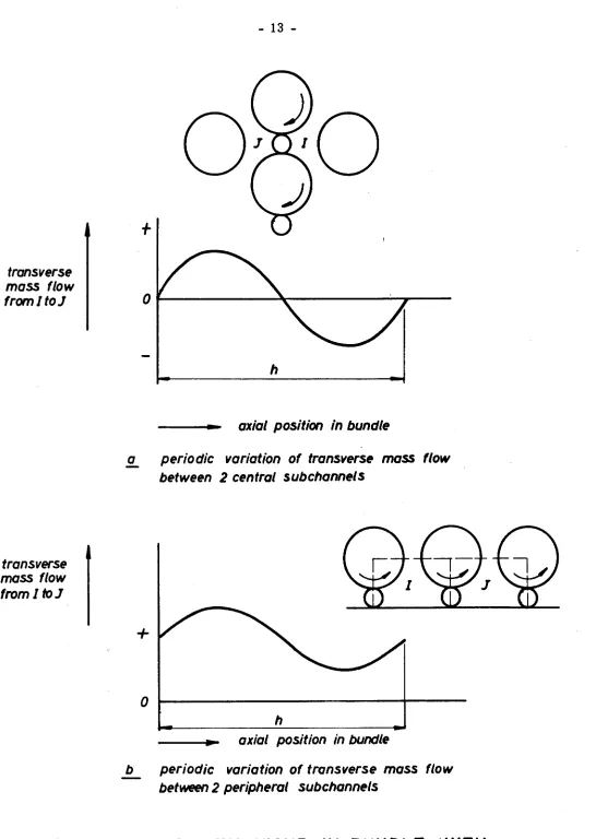
physical mechanism underlying mixing is here a periodic transverse mass
flow between adjacent subchannels, induced by the axially varying
circumfe-rential position of the spacer. The transverse mass flow between two central
subchannels and between a central subchannel and a peripheral subchannel
undergoes a periodic variation over characteristic axial distance intervals
h, changing direction at distance intervals h/Z. Here h
is
the axial spacer
pitch. The transverse mass flow between peripheral subchannels is of the
single direction type, varying only in magnitude over the characteristic axial
length h. The above behaviour is illustrated in Fig.
3.
At axial locations
where the spacer traverses the gap between rods in the direction from
sub-channel I towards subsub-channel
J
the transverse mass flow reaches maximum
values. The fluid, obliged to follow the spacer bodily into J, transports
en-thalpy at a rate given by:
~d ;
(3
{I) H {I,
J}
z
g
{l Z)
where (3(1) is a single direction convective transport coefficient given by:
d+d
s
(3(1) ;
d
?C- h
p
U {I, J)
.
s
g
{13)
In the above equations U {I,
J)
and H {I,
J)
represent the axial coolant velocity
g
g
and the coolant enthalpy respectively in the gap {I,
J).
For a correct
descrip-tion of the mixing behaviour in multirod systems with helical spacers it is
necessary to have information on the axial variation of transverse mass flow
(related to (3 {I)) and on the mixing behaviour within a single subchannel. The
latter providing the possibility to establish the difference H(I) - H (I,
J)
and
g
U{I) - U (I,
J).
g
12
-hexagonal fuel box
fuel rod
coolant region
helical spacing wire
axial
itch
a
-heli ea/ wire
b
-Fig. 2 HEXAGONAL
FUEL ROD BUNDLE WITH HELICAL
[image:12.709.128.645.49.763.2]transverse
mass flow
from/toJ
transverse
mass flow
from/
toJ
Fig. 3
13
-+
h
axial position in bundle
a
periodic variation of transverse mass flow
between
2 central subchannels
+
0 ...__ _ _ _ _ _ _ _ _ _ _ _ _
,.__ _ _
h
- -.... ~-
axial position in bundle
b
periodic variation of transverse mass flow
between 2 peripheral subchannels
[image:13.708.34.580.49.817.2]14
-mixing model, i. e. the intersubchannel transport effects are averaged
axial-ly. For interactions between central subchannelsor between a central
subchan-nel and a peripheral subchansubchan-nel where transport is of the two-direction type,
the following procedure is adopted:
(a) H (I,
J)
and U (I,
J)
are assumed to equal the bulk average values H(I) and
g
g
.
U(I) in the subchannel I from which the flow is being deflected:
{b) intersubchannel heat flows, alternating direction at axial distance
inter-vals h/2, are assumed to be constant in each of these interinter-vals and equal
to the predictions of the maxim.um rate expressions {12) and
(13).
This
results into the following expression for the mixing coefficient f3 (I,
J)
as
defined by eq. (2):
l
dtd
I,
~
f3
(I; J)
=
4
ds
'JtT
pLU{I)
+
U(J)J
(14)
One has to be careful in applying the continuous mixing model to
interac-tions between peripheral subchannels where a single direction transport
me-chanism is operative. It follows from continuity considerations that the
axial-ly averaged lateral mass flow between peripheral subchannels must be the
same for each subchannel. The value of U (I,
J)
in the "axially averaged
ver-g
.
sion" of eq.
(13)
thus ought to be a constant e. g. an averaged peripheral
sub-channel velocity U • Employing a procedure similar to that outlined above,
p
.
leads to the following rate expressions:
Q
_.h._
=
f3
(I) H(I)
dz
dtd
s
f3(I)
=
d
'Jt - -p U
s
h
p
(15)
(16)
Applying the above two equations in the matrix differential equation for the
subchannel coolant enthalpy distribution gives rise to an asymmetric matrix
with complex eigenvalues. This would give rise to additional complexity in
the present computer programme which was not considered justified. For
the peripheral subchannels therefore also a two-directional transport model*)
... 15
-was adopted with
f3
(I, J) given by:
l
dtd
[
~
f3
{I, J)
=
2
ds
?t~
P __
u(I)
+
U(J)J
(17)
Since intersubchannel mixing of momentum and heat are governed here by
the same mechanism, one has in view of eqs. (1) and (2) for the momentum
mixing coefficient
ex
(I, J)?
cx(I,
J)
=
/3
(I, J)/p
(18)
It is worth pointing out that expressions for the mixing coefficients also
may be specified as input data, instead of calculating the latter
wi.
th eqs. (16)
and (17).
2. 2
Subchannel coolant mass flow distribution
The chief aim is to compute the distribution of ~xially averaged
subchan-nel coolant mass flow rates. Axial changes in coolant density, leading to
acceleration pressure drop, are ignored and no consideration is given to axial
variations in subchannel mass flow due to the presence of spacing devices.
The computation procedure is illustrated for the case of a rod bundle with
grid type spacing.
A momentum balance set up for a subchannel I over the entire fuel
ele-ment length Z t yields:
-tw(I)W/I)
+
LN(I)cx(I,J)[pu(I) - pU(J)J
' - . , - - 1
friction
diffusional interchange with
neigh-bouring subchannels
+
-2
1
n c (I)PU(r/s(I)/zt
=
(P.-P
)S(I)/z
(19)
.
g g
l Ot
\ I
grid pre;sure drop
total pressure drop
Here W (I) and S(I) are the wetted perimeter and flow area of subchannel I,
p
whereas n and c (I) denote the total number of grids and the grid flow
re-g
g
16
-coolant pressure distribution at fuel bundle inlet and outlet. The average
subchannel wall shear stress
't(I} is related to the subchannel coolant flow
w
properties by:
't
(I}
=
1/2 f(I} P (I}
u(r)2
w
with the friction factor f(I) expressed by:
-EXF
(
~ (I)
p U{I})
f(I}
=
CFR
µ
(20)
(21)
Here
µ is the dynamic coolant vi~cosity {evaluated at the bulk average
cool-ant temperature in the fuel element}, CFR and EXF a.re constcool-ants (input data} and
~
(I} is the equivalent hydraulic diameter defined by:
d (I}
=
4
S(I)
n
W (I}
p
(22)
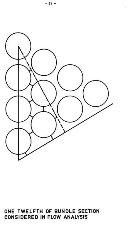
The attention is now focussed on the symmetry section. For the present
configuration this is one twelfth of the fuel bundle section, as is illustrated
in Fig. 4. Application of the mass conservation principle to this section
yields:
NM
with
L
GR(I)
=
1
1
G(I}
=
p
U{I} S{I)
GR(I)
=
G(I)/ Gt
(23}
(24}
(25)
NM
being the total number of subchannels and Gt being the total mass flow
rate.
17
-Fig. 4
ONE TWELFTH OF BUNDLE SECTION
[image:17.712.124.577.53.808.2]18
-(26)
This leads to:
G
[
FUF(I) +
t
S(I)
~
J
~
a(I J)
(P.-P
J
~(I)
ex
(I, J)
GR(I) - Gt ~(I) s(r)'. S(J) GR(J) -
~t
=
0(27)
for I
=
1 - NM.
Eqs. (23) and (27) represent a sy~tem of NM+ 1 linear equations with NM
unknowns GR(I) and the unknown value (P. -P )/Z • This system is solved by
1 0
t
matrix inversion. The computed values of GR(I) are then substituted in
eq. (26) to obtain a more accurate approximation of FUF(I). This computa-.
tion procedure is repeated until GR(I) and (P. -P )/Z differ by less than a
1 0
t
prescribed small amount from values determined in a preceding calculation.
2. 3 Subchannel coolant enthalpy distribution
A heat balance applied to a subchannel I over an axial increment dz yields
the following differential equation:
G(I)
~p)
=
QS(I)Hp(I) -
L
N(I)
(3
(I, J) [ H(I) - H(J)
J
(28)
where QS(I) is the average heat flux associated with subchannel I and Hp(I)
is the heated perimeter of subchannel
I.
The summation in the second right
hand term is again carried out over N(I) bounding subchannels. The above
equation may be made dimensionless as follows:
GR(r> dHR(r)
=
coscr). Hp(r)
cz _
\'L
N(r>
.1:.
~
er J)
r
HR(1)-HR(J>]
c29)
' dZR
QFRAT. PERS
.. /
Gt
JI
Here G is the total mass flow rate in the fuel bundle section consideredz),
t
L is the total heated length, whereas ZR and 'ttR(I) are dimensionless
va-riables defined by:
z
Z R =
-zTOT
H(I) - H.
HR(I)
=
in
6H
19
-(30)
(31)
H. being the inlet enthalpy and
ti
H being the axial bulk coolant enthalpy rise
lll
over the fuel rod bundle. In the first right hand term of eq. (29) only CZ
de-pends on axial position, it is given by:
CZ
=
QFZ
QFO
(32)
where QFZ and QFO are cross sectionally averaged heat fluxes at position
ZR and at the channel centre respectively. PERS is the heated perimeter of
the section considered and QFRAT is given by:
QFRAT
=
QFAV
QFO
(33)
where QFAV is the spatially averaged fuel l;>Undle heat flux. The parameter
CQS(I) is defined by:
CQS(I)
=
QS(I}
QFZ
(34)
The fact that CQS(I) is invariant with axial position implies the assumption
that the axial power distribution is the same for all fuel rods.
Eq. (29) can be brought in the slightly modified form:
GR(I) d~:g)
=
D(I,
.I)
HR(I)
+
l}(I) D(I, J) HR(J)
+
GR(!) QRz(I)
(35)
where
D(I, J)
=
Z TOT
'3(!,
J)
C\
D(I, I)
= -
fN(I) D(I, J)
1-.J
_ CQS(I). Hp{I) C
Z
QRz(I) - QFRAT. PERS GR(I)
(36)
(3 7)
{38)
20
-(39)
Here_[GR
J is a diagonal matrix of dime.nsionless subchannel mass flow rates
and
l
A]
is a symmetric matrix of dimensionless intersubchannel mixing
co--. :.t
efficients D{I,
J) ),
whereas
[ :~J ,
[HR
J
and [ QR z
J
represent column vectors of dimensionless
enthalpy gradients, dimensionless enthalpies and dimensionless heat input
terms respectively.
The linear first order matrix differential equation {39) is solved by
apply-ing an eigenvector expansion. The linear transformation carried out for this
purpose is:
[HR
J
=
jVEJ [ HT
J
(40)
where [vE
J
is the eigenvector matrix of [E ] , the latter being given by:
Substituting eq. {40) into eq. {39) and premultiplying by [vE
J-l yields:
(42.)
where lrVE J - l [ E ] r E ] represents a diagonal matrix with the eigenvalues
y(I) o/[EJ on the diagonal. Hence
[:~ J
=
['v<1)
.J [
HT
J
+ [
R z
J
(43)
In the above expression
r
R z
J
is the column vector of transformed
subchan-nel heat input terms resu)ting by carrying out the indicated matrix
multipli-cations on the second right hand term of eq. (42.). Eq. (43) represents an
21
-uncoupled system of first order differential equations in terms of the
trans-\
formed enthalpies HT(I) which can be written in an alternate way as:
dHT(I)
dZR
=
Y
(I). HT(I)
+
R/1), I
=
1, 2, ••• NM
(44)
The problem now has been reduced to the solution of the algebraic
eigen-value problem;
(45)
where [
V]
is the eigenvecto.rcorresponding to a given eigenvalue
y .
For obtaining the solution of eq.
(45)
advantage is taken of the fact that [ GR]
and [ A J
represent real symme_tric matrice~, the former being in addition
positive-definite and diagonal. Once the full set of eigenvalues Y (I) for
I
=
1, NM
and the matrix
VE
of associated eig.envectors
I
V
1
, V
2
, V
3
, ••• V NM
J
has been evaluated, the differential equation system
(44)
can be solved in a
straightforward manner. One directly obtains:
HT(I)
=
B(I) exp[
y
(I) ZRJ
+
P
z(I)
{46)
where
P
(I) is the particular solution due to the heat input term R (I).
z
z
Account now still has to be taken of the initial conditions for HR(I) at Z
=
O,
which can be specified as an initial condition for HT(I) using the
transforma-tion:
{47)
The solution in terms of HR(I) is obtained by carrying out the back
transfor-mation indicated by eq. {40).
2. 4 Aspects related to the spatial variation of fuel heat generation
gene 22 gene
-ration is the same. Axial variation of heat gene-ration is arbitrary and is
ex-pressed in terms of the following Fourier series expression:
QFZ
CZ
=
QFO
=
NAT
[
AFL{N) sin(~;~)+ CONS
1
{48)
Fig. 5 provides explanations with regard to the parameters used in the above
expression. The heat generation region extends from Z
=
0 to Z
=
ZTOT.
Beyond this region the heat generation curve may be extrapolated. At Y
=
0
the normalized heat generation te~m CZ has a prescribed value CONS, where
0
~CONS
~CZ . , CZ .
representing the minimum value of CZ at either
m1n
m1n
Z
=
0 or at Z
=
ZTOT. From Fig. 5 it now appears that the extrapolated
length ZEX is given by
ZEX
=
YOl + Y02 + ZTOT
{49)
The coefficients AFL{N) in eq. {48) are determined by matching eq. {48) with
a specified axial distribution of heat generation at a prescribed number NAT
axial positions.
The spatially averaged value of C Z is
cz
=
QFAV
=
1
av
QFO
ZTl)T
In view of eq. {48) we have
NAT
ZTOT
I
CZ dZ
0
given by:
cz
=
av
ZEX
7CZTOT
~
AFL(N). DIFCO(N)+ CONS
where
DIFCO(N)
=
.!. '..
~zYOl) _
(N7t(ZTOT+Y01))]
N
I
cos \. ZEX
cos
ZEX
{50)
{51)
(52)
It is worth pointing out that when the axial heat generation distribution is
not the same for each rod, the computer programme has to be modified in
[image:22.592.46.531.468.723.2]distribu-- distribu-- distribu-- distribu--
extrapolated curve beyond heating region
CZ=1
CZ=CZmin
total heated length
z
TOT
CZ= CONS
extrapolated le,ngth ZEX
/ / I
/
I
YOf
Z• ZTOT/2
y
- - - z
f
START OF HEATING
Fig. 5
AXIAL VARIATION OF HEAT GENERATION
'
'
\
\
\
QFZ
CZ= QFO
,,,
Y02
normalized
heat
generation
~
[image:23.874.19.850.65.586.2]24
-tions.
2. 4. 2 Variation of heat generation in the lateral direction
---The following assumptions are made: (a) the value of fuel heat generation
in a rod bundle cross section depends on the radial distance from the core
centre only, {b) the radial distribution of fuel heat generation has the same
shape for all axial positions. The position of the hexagonal fuel box with
re-\
gard to the reactor core centre is that shown in Fig.
6.
For this
configura-tion the lateral variaconfigura-tion of heat generaconfigura-tion attains a maximum along the
dia-gonal of the hexagonon.
The radial variation of fuel heat generation is represented by the polynome
expression:
QLR =
B
O -
B
1
•
RD -
B
2
RD
2
(53)
where QLR is the linear power at a radial distance RR normalized with
res-pect to that of the fuel rod with maximum rating in the fuel box. RD is a
di-mensionless distance parameter given by:
RR
RD= RO+ ZL
(54)
where RO is the radial distance from the core centre of the rod {centre) with
highest rating and ZL is the distance betwee,n the centres of the most distant
rods in the hexagonon. Defining VX as the variation of heat generation along
the hexagonon diagonal {between the centres of the most distant rods),
nor-malized with respect to the heat generation of the rod with maximum rating
and introducing
(55)
we have, since by definition QLR = 1 at RR = RO,
vx
(56)
Reactor core
centre
Fig. 6
"
"
/
/
I
I
/
/
power decrease in RR direction
fuel rod with minimun rating
fuel rod with maximun rating
POSITION OF HEXAGONAL FUEL BOX WITH RESPECT
TO REACTOR CORE CENTRE
26
-(57)
(58)
where ZLD
=
RO
t
ZL
ZL
(59)
RO
RDO
=
RO+ ZL
(60)
The parameters VX and RATA are specified as input information.
3. DESCRIPTION OF THE HERA-lA COMPUTER PROGRAMME
3. 1 Topographical considerations
As outlined previously the specific rod bundle geometry considered in
HERA-lA is the hexagonal fuel rod bundle of which a cross section is shown
in Fig. 7. A regular array with equal rod spacing is considered. The
geome-try therefore is fully defined when the following data are specified:
- the number of rod rows NROMA
- the outer cladding radius RC
- the pitch to diameter ratio P
- the dimensionless rod-wall distance PW
According to their position in the bundle one may distinguish central
channels and peripheral subchannels and according to shape triangular
sub-channels (NTYP
=
1 ), rectangular subchannels (NTYP
=
2) and angular
sub-channels (NTYP
=
3).
For the calculation of the subchannel coolant mass flow distribution it is
sufficient to consider the symmetry section presented in Fig. 8 a%) i. e. one
twelfth of the bundle section. The heat transfer analysis is aimed at
evalua-z)
Strictly this is not true for the case of a bundle with helical spacers, where
RC
NROMA ( here 2) rows
of outer rods
27
-peripheral subchannel
central subchannel
angular subchannel
(NTYP=3)
rectangular subchannel
(NTYP= 2)
triangular subchamel
(NTYP=1)
central rod
a
Symmetry section for
flow analysis
28
-considered
for NGE=1
b
Symmetry section for
heat transfer analysis
[image:28.705.139.646.65.828.2]29
-ting the effect of a lateral power gradient along the hexagonon diagonal. For
this case it is sufficient to consider half a hexagonon:t) as indicated in Fig. 8 b.
To establish in a straightforward manner which subchannels interact with
each other it is important to number the subchannels in a suitable manner.
Two methods have been adopted simultaneously here. In the first method two
indices are assigned to a given subchannel, one denoting the subchannel row
NRO and one denoting the number NUM in a given row. In the other method
subchannels receive each a single identification number ranging from 1 till
NM. Fig.
9
illustrates this for the half hexagonon. The ·two ways of indexing
are connected by the expressions:
I= NOT {NRO, NUM)
NRO = NROW (I)
NUM = NUMS(I)
(61)
(62)
(63)
For the heat transfer situation considered i. e. power variation along the
diagonal usually intersubchannel heat transport in the direction normally to
the diagonal is of negligible importance. For this situation it mostly is
suf-ficiently accurate to consider one or two rows of subchannels along the
dia-gonal. Fig. 10a and b illustrate these .. alternatives. Another possibility
pro-vided by HERA-lA is to consider NRY rows of outer subchannels in half a
hexagonon, as is illustrated in Fig. 10 c. Selection of the above rod bundle
sections has the obvious advantage of reducing the number of subchannels and
hence the computation time involved in the solution of the eigenvalue problem.
3. 2 Specification of input data
This paragraph deals with a description of the input data.
~~!.?-~~1::.:.} _
specifies selection numbers affecting the type of
NUM=9
NUM=3
NR0=1
NR0=2
NR0=3
3·1
a
subchonnels with
indices NRO~ NUM
30
-13
[image:30.700.134.688.51.790.2]b
subchannels with
a single index I
a
11
single row of
subchannels
along diagonal
(NGE•2)
c
NRY (here 2) rows of
outer subchannels
(NGE• 4)
31
-37
22
,
.b
two rows of
subchannels
along diagonal
(NGE:JJ
[image:31.701.64.569.32.850.2]32
-tions to be carried out. NGE determines the geometry for which calcula-tions
are carried out. NGE
=
1 corresponds tohalf a hexagonon; NGE
=
2 to a single
row of subchannels along the diagonal and NGE
=
4 to NRY rows of outer
sub-channels in half a hexagonon. NSP determines the type of spacer, NSP
=
1
cor-responding to grid spacers and NSP
=
2 corresponding to helical spacers.
NFLOW denotes the type of input related to the rod bwidle mass flow rate.
For NFLOW = 1 the mass flow rate is computed from a prescribed axial
cool-ant temperature rise DELTC, for NFLOW = 2 the mass flow rate is specified.
NMIMO regards intersubchannel momentum transport, for NMIMO = 1 it is
dis-regarded. for NMIMO = 2 it is taken into consideration. NMill has a
similar
ef-fect on intersubchannel heat transport. NCON determines whether conduction
con-tributes to intersubchannel heat transport {ohly for grid type spacers). For NCON=l
there is no contribution, for NCON = 2 conduction is taken into accowit.
NKG {only for grid type spacers) regards intersubchannel mixing by grids.
For NKG = 1, no mixing at grids, for NKG = 2, accowit is taken of mixing
at grids. NMDC regards intersubchannel mixing for helical spacers. For
NMDC = 1 mixing input data are employed, for NMIX = 2 the maximum
mixing rate expressions {14) and (17) are used.
Card number 2 specifies options. For NOP having values above 1 control
data are printed. NGA is the number of additional computation cases with
different spatial heat generation distributions {for the same fuel element
power as the first case).
Card number 3 specifies the total number of rod rows NROMA in the bundle
and the number of outer subchannel rows NRY (to be taken into
considera-tion for NGE = 4).
Card number 4 specifies the pitch to diameter ratio P, the dimensionless
rod-wall distance PW, the fuel radius RF and the outer cladding radius RC.
33
-length (unheated part included) ZUN, the heated rod bundle -length ZTOT,
the axial length increments YO! and Y02 related to the axial heat
genera-tion distribugenera-tion (see Fig. 5), the axial distance ZIC of the first grid from
the fuel bundle inlet, the axial distance between grids ZC.
Card number 5 specifies for helical spacers (NSP
=
2) ZTOT, YO!, Y02
and the axial spacer pitch ZG.
Card numbe.r 6_ specifies for NFLOW
=
2 the total fuel bundle mass flow
rate.
Card number 6 specifies for NFLOW
=
1 the
axial
coolant temperature
rise DELTC in the fuel element.
Card number 7 specifies for grid type spacers {NSP
=
1) the coefficient
CFR and the exponent EXF in friction factor expression (21), grid flow
resistance coefficients CGI, CG2 and CG3 for a triangular subchannel, rec
-tangular subchannel and angular subchannel (see Fig. 7), the coefficient
CEF in the turbulent diffusivity expression (7) and the grid mixing
coeffi-cient GAMMA ( y{I, J} in eq. {11}} •
Card number 7_ specifies for helical spacers {NSP
=
2) CFR, EXF and
intersubchannel mixing coefficient parameters CMIXl and CMIX2 which
correspond to j3(I, J)/[p U{I)
+
pU(J}J in eqs. (17) and {14) respectively.
Card number 8 specifies fuel conductivity VLF, the cladding conductivity
VLCL and the fuel-cladding contact resistance BETA.
Card number 9 specifies the coolant temperature TIN and the coolant
pres-sure PIN at the inlet of the fuel region.
Card number
10_
specifies the maximum linear power QLMAX{W /m} of the
rod with the highest rating.
34
-along the diagonal (see 2. 4. 2), the radial distance RO of the rod with the
highest rating from the reactor core centre and the coefficient ratio RATA
defined by eq. (55).
Card number 12 specifies the number of axial positions NAX
(i.
e. for
grid spacers between two grids, for helical spacers along the entire fuel
rod bundle), at which computation results are furnished, and the number
of axial positions NAT at which eq. (48) is matched to the prescribed axial
power distribution.
Card number 13_ specifies the axial positions ZI(NA) at which the heat
ge-neration is specified.
Card number 14 specifies the parameter CONS (see eq. (48) and Fig. 4)
the heat generation term QFRO at Z
=
ZTOT/2, the maximum heat
genera-tion QFRMA and the heat generagenera-tion terms QFRZ(NA) corresponding to
ZI(NA). Note that the latter three parameters can be specified in arbitrary
(but the same) units.
It
is worth pointing out that, unless otherwise specified, all data figuring
in the input are in kg/m/sec units.
3. 3 Outline of programme structure
An approximate idea of the HERA programme structure can be obtained
from the simplified flow diagramme shown in Fig. 11.
After reading of the input data, the geometry parameters of the hexagonal
rod bundle are computed (channel dimensions and sections, wetted perimeters,
heated pe,rimeters, hydraulic diameters, thermal diameters of subchannels).
It
is worth pointing out that for the case of helical spacers {wires) axially
averaged values of geometry parameters are determined.
Subsequently consideration is given to the spatial heat generation
deter-no
READING OF
INPUT DATA
COMPUTATION OF
GEOMETRY
PARA-METERS
COMPUTATION OF AXIAL
FLUX PARAMETERS AND
· BUNDLE POWER
EVALUATION OF
INTERSUB-CHANNEL MOMENTUM
MIX-ING COEFFICIENTS
COMPUTATION OF COOLANT
MASS FLOW DISTRIBUTION IN
SYMMETRY SECTION
INDEXING OF
SUBCHANNEL-GEOMETRY AND -FLOW
PA-RAMETERS FOR HEAT
TRANS-FER GEOMETRY
35
-continued
EVALUATION OF
INTER-SUBCHANNEL HEAT MIXING
COEFFICIENTS
SOLUTION OF EIGENVALUE
PROBLEM OF TRANSPORT
COEFFiaENT MATRIX
SOLUTION OF MATRIX
DIFFER-ENTIAL EQUATION FOR
SUB-CHANNEL COOLANT ENTHALPY
EVALUATION OF SUBCHANNEL
COOLANT ENTHALPY
EVALUATION OF SUBCHANNEL
COOLANT TEMPERATURES AND
OTHER DERIVED THERMAL
PARAMETERS
PRINTING OF DATA
Fig. 11 - Simplified Flow Diagramme of HERA-lA
[image:35.717.17.570.34.757.2]36
-mined using a matrix inversion technique (subroutine INMAT). The
subrou-tine RODFLU is employed to calculate QFRAT2, the ratio of cross
section-ally averaged heat flux to that of the rod with highest rating, and the linear
powers associated with each rod in half the hexagonon. Finally the fuel bundle
power POW is calculated.
In treating the coolant flow aspects attention is first given to physical
pro-perties and bulk flow characteristics. Depending on whether NFLOW has the
value 1 or 2, the total coolant mass flow rate FMTOT is determined from
the axial coolant temperature rise DELTC, or DELTC is determined from
FMTOT. The enthalpy-temperature relationships for the coolant (sodium),
employed in this calculation are given by the functions FUNH(T) and FUNT(H).
Physical properties VRHO, VMUF and VA are taken at the bulk average
cool-ant temperature TCAV. The bulk coolcool-ant velocity UB and the fuel element
Reynolds numbe_r REFU now are calculated. For determining the subchannel
mass flow rates the attention is focussed on the smallest symmetry section
(see Fig. 7 a). The subroutines INDEX and SECDIA are employed to number
subchannels and to furnish indices to subchannel geome,try parameters in this
section. First the subchannel coolant mass flow rates (FMR(I), normalized
with respect to the section coolant mass flow rate FMCS, are determined for
"zero" intersubchannel mixing. Provided NMIMO h.ts a value exceeding 1,
account is taken of intersubchannel mixing. The subroutine INAC establishes
'-which subchannels interact with each other. For the case of turbulent
diffu-sion (for NSP
=
1 only) the subroutine FIFU establishes turbulent interaction
terms FSFl, FSF2, FSF3, FSF4, corresponding to integrated values· of the
geometry dependent part of eq.
(9).
For grid spacers {NSP
=
1) the
intersub-channel momentum mixing coefficients VM(I,
J)
are evaluated by the
subrou-tine MI~U, for helical spacers {NSP
=
2) this is done by the subroutine HELMIX.
The values of FMR(I) {equivalent to GR(I) in eq. (25)) are now determined by
solving eq. (27) iteratively.
37
-bundle section under consideration. This is done
by
calling the subroutines
INDEX and SECDIA. The subchannel coolant mass flow rates evaluated for
one twelfth of the bundle section, are associated with the subchannels in half
a hexagonon making use of the subroutine TRANS. The subroutine RODSUB
is used for evaluating the average subchannel heat fluxes CQS(I) normalized
with respect to the cross section averaged heat flux QFZ (see eq. (34)). The
essential input information for RODSUB regards the fuel rod ratings already
established by the subroutine RODFLU. Provided NMilI is larger than one,
account is taken of intersubchannel interactions. Depending on the rod bundle
section considered, it is established which subchannels interact with each
other
by
calling the subroutines INAC (NGE
=
1, NGE
=
4) or INAC2 (NGE
=
2,
NGE
=
3). lntersubchannel .heat mixing coefficients VM(I,
J)
are established
by subroutines FIFU and MIFU for grid spacers (NSP
=
1) and by subroutine
HELMIX for helical spacers (NSP
=
Z).
The attep.tion is now turned to the
solution of the eigenvalue problem. The coefficient matrix [ A] in eq. (39)
is constituted by the elements VM(I,
J)
as computed by loops 210 and 211 of
the main programme. The eigenvalues EIVR(I) (Y(I) in eq. (44)) and the
eigen-vector elements VM(l,
J)z)
of the matrix [E
J
as defined by eq. (41) ·are
de-termined by the subroutine EIVA. The basic information underlying the
solu-tion of the matrix differential equasolu-tion for the subchannel coolant enthalpy is
now available. In the loop 225 the normalized subchannel coolant enthalpies
HR(I), defined by eq. (31), are computed at specified axial positions. In
ad-dition a number of derived thermal parameters are evaluated. Among others
the subchannei coolant temperature TCO(I) and the average subchannel
clad-ding temperature TCL(I). In evaluating the latter,· use is made of a
conven-tional heat transfer coefficient expression. In the presence of grid spacers
and for values of NKG exceeding 1 account is taken of subchannel coolant
mixing at grids according to eq. (11). In addition to the above parameters,
\
the fuel centre temperature of the rod with the highest rating is also
deter-mined at the various axial positions.
38
-It is worth pointing out that for NGA larger than 1 additional heat
genera-tion patterns can be examined without repeating the solugenera-tion of the eigenvalue
problem! After having computed the first case, additional sets of cards (from
card number 11 onwards} are read. Aftef having newly calculated the heat
generation parameters, it is immediately proceeded with the computation of
subchannel coolant enthalpies and derived thermal parameters.
4. CONCLUDING REMARKS
The computation procedures underlying the HERA computer programme
provide the possibility of a rapid and efficient thermal analysis based on
ap-1
plication of the subchannel concept, of fuel rod bundles with single phase
cooling. The present version of HERA considers a liquid metal coolant
(so-dium} and a hexagonal bundle geometry. The same programme can be easily
modified for application to other coolants and other bundle configurations.
For a different coolant one only has to change the 5 "physical property
func-tions" at the beginning of the main programme. Other bundle configurations
require a number of minor modifications in the "geometry chapter" of the
main programme and changes in a few subroutines (essentially, INDEX,
INAC and RODSUB},
39
-Although the HERA programme can be used for thermal analysis of very
large rod bundles, it has been used by the authors only for bundles with a
maximum of 100 subchannels. This in order to avoid waste of computation
time, which on the IBM370/165 computer for the 100 subchannel case is about
%
1.
5 min.
). Much larger fuel rod bundles can be considered by focussing on
certain characteristic regions in the bundle (e. g. in the present HERA
ver-sion for NGE
=
2, 3 and 4) where most important temperature variations may
be expected. Work will however still be undertaken by us to develop methods,
resting on the same basic principles for analysis of systems with a very large
number of subchannels (say 500) without necessitating significantly more
com-putertime and -storage than presently required.
ACKNOWLEDGEMENT
Stimulating discussions with Messrs. I. GALLIGAN! and G. DI COLA on
problems related to solution of algebraic eigenvalue problems, are gratefully
acknowledge d.
Symbol
a
[A
J
BETA
CEF
CFR
C
g<r)
J
CG{I)
CGl, CG2, CG3
C MIXl, C MIX2
CONS
CQS{I)
cz
d
d
s
DELTC
NOMENCLATURE
(Symbols of text and most important symbols of listing)
Definition
thermal diffusivity (m
2
/ sec}
matrix of dimensionless intersubchannel mixing
coefficients
fuel-cladding contact resistance (m
2
0c/w)
coefficient in turbulent diffusivity expression
coefficient in friction factor expression
flow resistance coefficients of grid in subchannel (I)
flow resistance coefficients of grid in triangular,
rectan-gular, and angular subchannel
Observations
text
text, eq. (39)
input
input, eq. (7)
input, eq. (21}
eq. (19}
input
parameters related to mixing in bundles with helical spacers
I
input
prescribed value of heat generation parameter CZ at
Y=O
input
average subchannel heat flux normalized with respect to the
eq. (34)
cross section averaged heat flux
normalized heat generation term
I
eq. (48)
outer diameter of rod (m)
I
text
diameter of spacing wire (m)
r
text
axial bulk coolant temperature rise (°C)
I
input
(if
NFLOW
=
1)
Symbol
~(I)
J
DH(I)
EXF
EIVR(I)
A'
f(l)
FMCS
FMTOT
FMR(I)
G(I)
G
t
GR{!)
GAMMA
h
H
1.
m.
q>H{I)
HIN"
HOUT
HR(I)
fiH
Definition
hydraulic diameter of subchannel (m)
exponent in friction factor expression
eigenvalue
subchannel friction factor
mass flow rate in symmetry section (kg/sec)
bundle mass flow rate (kg/ sec)
normalized subchannel mass flow rate
subchannel mass flow rate
mass flow rate in symmetry section (kg/sec)
normalized subchannel mass flow rate
grid mixing coefficient
axial pitch of helical spacer
radially averaged coolant enthalpy {J/kg)
subchannel coolant enthalpy {J /kg)
inlet coolant enthalpy (J /kg)
outlet
II II IInormalized subchannel coolant enthalpy
axial bulk coolant enthalpy rise (J/kg)
Observations
input, eq.
(21)
( =
Y(I))
text, eq. {21)
text, {=FMCS)
text, {= FMR{I))
input, ( =
y{I,
J))
text, {=
ZG)
text, eq. (
4)
eq. {31)
i,i:,.
Symbol
Hp(I)
J
HPER(I)
HT(I)
n
g
N(I)
NAT
NAX
NCON
NFLOW
NGE
NKG
NM
NMIH
NMIMO
NMIX
NOP
NSP
NROMA
NRY
Definition
subchannel heated perimeter (m)
transformed normalized subchannel coolant enthalpy
total number of grids in bundle
number of bounding subchannels of a subchannel I
number of axial positions used in matching of heat
gene-ration' distribution
number of axial positions at which output is specified
selection numbe_r related to heat conduction in mixing
selection number related to bundle mass flow rate
'
selection number related to geometry
selection number related to grid mixing
total number of subchannels
selection number related to inte_rsubchannel heat mixing
selection number related to intersubchannel momentum
mixing
selection number related to mixing with helical spacers
selection number related to printing of control data
selection number related to type of spacer
number of rod rows (around central rod)
number of outer subchannel rows
eq.
(47)
text
text
input
Observations
input (see 3. 2)
input
input
input
input
input
input
input
input
input
input
input (for NGE
=
4)
•
~