Throughput Maximization Based on Optimal Access
Probabilities in Cognitive Radio System
Mohamed Elalem, Lian Zhao
Electrical and Computer Engineering Department Ryerson University, Toronto, Canada Email: [email protected], [email protected]
Received February 11, 2013; revised March 15, 2013; accepted April 15, 2013
Copyright © 2013 Mohamed Elalem, Lian Zhao. This is an open access article distributed under the Creative Commons Attribution License, which permits unrestricted use, distribution, and reproduction in any medium, provided the original work is properly cited.
ABSTRACT
Well-established fact shows that the fixed spectrum allocation policy conveys to the low spectrum utilization. The cog-nitive radio technique promises to improve the low efficiency. This paper proposes an optimized access strategy com-bining overlay scheme and underlay scheme for the cognitive radio. We model the service state of the system as a con-tinuous-time Markov model. Based on the service state, the overlay manner or/and the underlay manner is/are used by the secondary users. When the primary user is not transmitting and only one secondary user has the requirement to transmit, the secondary system adopts the overlay scheme. When the primary user is transmitting and the secondary users want to transmit simultaneously, an underlay scheme with an access probability is adopted. We obtain the optimal access probability in a closed form which maximizes the overall system throughput.
Keywords: Cognitive Radio; Access Probability; Underlay/Overlay Schemes; Marckov Model
1. Introduction
The wireless spectrum resource has become the major bottleneck for the development of the future wireless communications. Recent researches in spectrum-sharing techniques have enabled different wireless communica-tion technologies to coexist and cooperate towards achie- ving a better gain from the limited spectrum resources. This started when spectrum utilization measurements showed that most of the allocated spectrum experiences low utilization [1]. Certain authorities, as Federal Com-munications Commission (FCC) for radio spectrum regulation, divide the radio spectrum into many fre-quency bands, and licenses for the often exclusive usage of these bands are provided to operators, typically for a long time. Depending on the type of radio service that is then provided by the licensees, frequency bands are often idle in many areas, and inefficiently used. The concept of spectrum sharing (the coexisting of different radio sys-tems in the same spectrum) then occurred [2], as one device may transmit, while others in the area are idle. Moreover, radio systems can dynamically use and release spectrum wherever and whenever they are available. This dynamic spectrum access helps to minimize unused spe- ctral bands.
In spectrum sharing systems, the secondary user can adopt two types of access schemes: overlay scheme and
underlay scheme. In underlay scheme, the licensed spec-trum band can be accessed without considering the pri-mary user’s activities, but with strict power constraint. In overlay scheme, the secondary user senses the spectrum bands and accesses the unused spectrum spots. The sec-ondary users must be ceased when the primary user ap-pears in the band and resumed when the primary user finishes its service.
The different features of these two schemes enable them to make up with each other. In [3,4], the papers give a mixed access strategy: When the channel is being used by the primary user, the secondary users access the channel with a probability in underlay manner. When the channel is idle, they choose to access in overlay manner.
There have been several previous efforts addressing these two schemes from different points of view. In [3], the authors study the capacity of the secondary users and the impact of the primary user’s activities for both schemes. The authors in [5] conclude that the overlay spectrum sharing strategy offers higher network capacity and the interference threshold limits the capacity in the overlay strategy more than its underlay capacity.
dary users cannot operate simultaneously on the same spectrum band, then a Continuous Time Markov Chain (CTMC) is proposed to model the interactions between these different users. They derive a tradeoff between spectrum efficiency and fairness. However, the optimal access probability is not a precise value. An optimal ac-cess probability with different criteria is given in [8] for pure underlay scheme.
Based on [8], this paper proposes a mixed overlay and underlay access scheme. The secondary users access the channel with an optimal probability in an underlay scheme when the spectrum is occupied by the primary user. Meanwhile, when the spectrum is idle, the secon-dary users access the channel in an overlay manner. This approach can maximize the total average throughput for the secondary users and limit the interference on the pri-mary user.
The optimized access strategy proposed in this paper is similar in spirit to the work done in [8]. We further in- troduce a new optimized parameter () to determine the best access probability to achieve the highest throughput. Closed forms for the achieved capacity are provided as well as the optimized access parameters.
The rest of this paper is organized as follows. Section 2 introduces the system model and assumptions. In Sec-tion 3, the maximal throughput expressions for the two schemes are given. The optimal access strategy for equi- probability case is introduced in Section 4. While Section 5 introduces the case of unlike access probability. Per-formance analysis and simulation results are given in Section 6. Finally, the paper is summarized in Section 7.
2. System Model and Assumptions
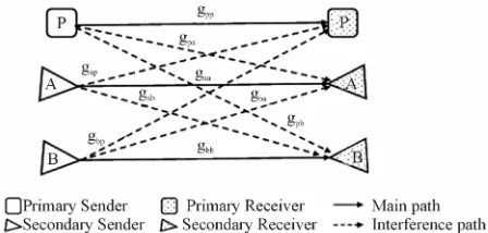
Figure1 illustrates the system model which consists of a primary user (P) and two cognitive users
A B,
shar-ing a W Hz wireless channel. It is assumed that both nitive users can sense the primary user perfectly. A cog-nitive base station is assumed to make the cogcog-nitive users exchange their information among them. An example of these information is the real-time service state. The ser-
Figure 1. The additive interference channel for a pair of primary and cognitive links with channel gain coefficients:
pp ss ps sp g ,g ,g ,g
.
vice state indicates a user’s requirement for transmitting at specific time. The primary user can employ the chan-nel without considering secondary users’ service state.
The traffic pattern of the primary and the two secon-dary users is modeled as independent Poisson processes with arrival rates P, A and B, respectively.
The service times are assumed to be exponentially dis- tributed with rates P, A and B, respectively. We
define service state of the system as the sum service state of all the users in the system at a moment. Based on the individual’s service state, we get the service state set for the system as
0, , , ,P A B AB PA PB PAB, , ,
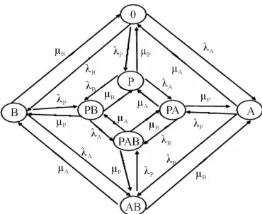
. State “0” represents there is no user tends to transmit on the channel; State “P” represents only the primary user is transmitting on the channel; State “A” represents only user A wants to transmit on the channel; State “B” repre-sents only user B wants to transmit on the channel; State “AB” represents both cognitive users want to transmit on the channel at the same time; State “PA” represents user A wants to transmit on the channel while the primary is transmitting; State “PB” represents user B wants to transmit on the channel while the primary user is trans-mitting; State “PAB” represents both A and B want to transmit on the channel while the primary user is trans-mitting. These states in the cognitive radio system can be modeled as an eight-state continuous time Markov model, as shown in Figure 2 [8].The rate at which transitions take place out of state si
equals to the rate at which transitions take place into state sj. The normalization equations governing this flow
bal-ance can be written as
0
0 0
π π π
π π π π
π π π π
π π π π
π π π π
π π π
π π π
P A B P P A A B B
P A B P P PA A PB B
A P B A A AB B PA P
AB P A B A B B A PAB P
PA B P A A P P A PAB B PB A P B B P P B πPAB A
π
PAB P A B PA B PB A AB P
(1)
where πsi represents the steady-state probability of be-ing in state si and siΦ. Also we have
0
π π π π π
π π π π 1.
si si P A B
AB PA PB PAB
(2) The steady state probabilities for all the states can be found by solving the set of the linear Equations (1) and (2).
3. Secondary User’s Maximal Throughput
[image:2.595.60.284.588.695.2]Figure 2. The continuous time Markov model of the service state and the flow balance.
cess the spectrum hole which is currently not used by the primary user. They can not co-exist on the same spectrum band. If one secondary user is transmitting, the only in-terference is the background noise. The user A or B ac- cesses the channel with power o
s
S . Since in the overlay
manner, only one user can transmit, the maximal data rate for each of them individually is
2 2
log 1
o
o aa s
A s g S R W
(3)
2 2
log 1
o
o bb s
B s g S R W
(4)
where 2 s
is noise power. These rates can be achievable with the following corresponding probabilities:
, ,
π and π ,
o A o B
A B
P P
respectively.
3.2. Maximal Throughput for Underlay Scheme Unlike the overlay scheme, in the underlay system, sec-ondary users are allowed to share the channel simultane-ously with the primary user pledging not to violate the limit of interference which is assumed as th.
I
Since the secondary users A and B can get the service state of the system with the help of their base station, A and B make access decision based on the service state of the system. Here, there are two possible service state sets. When the service state is siΦ1
A B,
, which indicates the primary user P is not transmitting and only one secondary user has the requirement to transmit. The other case is when the service state
2
Φ , , ,
i
s PA PB PAB AB , which indicates that the
primary user is transmitting or both secondary users want to transmit at the same time. User A and B have to adopt their powers u
s
S to access the channel with probabilities
, A
and B, respectively in the underlay scheme. In order to protect the primary user and decrease the mutual interference between secondary users, we assume that
u s
S satisfies the minimum SINR requirement.
These probabilities A and B determine the sum throughput of the secondary users and the interference on the primary user. When A and/or B are large, the sum throughput may be large and the chance to coexist with primary user is large, too. Our goal is to obtain op-timal access probabilities to maximize the total secon-dary throughput, while limit the interference on the pri-mary user. The service state set of the system in the un- derlay manner is Φ2. Hence the actual access state set is
, ,
3
Φ A B P, , ,
A PB PAB AB
. The users’ maximal data rates under each state in the underlay manner is given in as , , , , , , , u PA A u PB A u A A u B B u AB A u AB B u A 2 2 2 2 2 2 2 2 2 2 2 2 log 1 log 1 log 1 log 1 log 1 log 1 u aa
p pa s
u bb
p pb s u aa s u bb s u aa u ba s u bb ab s p g S R W S g g S R W S g g S R W g S R W g S R W S g g S R W S g R 2 2 2 2 log 1 log 1 u aa u
p pa ba s
u bb
u
p pb ab s
g S W
S g S g
g S
R W
S g S g
, PAB u PAB B , u s i R i (5)
where ,
A B,
,sΦ3 denotes the i’s maximal data rate for the underlay case. The term
,
, ,ij ,
g i j p ab is the channel power gain between the
transmitter of the user i and the receiver j as shown in Figure 1. Sp is the transmit power of the primary user.
The corresponding probabilities of these rates are:
, π 1 π
u PA
PA PAB
P (6.a)
, π 1 π
u PA
PA PAB
P (6.b)
, π 1 π
u PB
PB PAB
(6.c)
is a probability value (i.e.,
, 1 π
u A
AB
P
(6.d)
, 2π
u AB
AB
P (6.e)
, 2π
u PAB
PAB (6.f)
P
4. Equiprobability Optimal A
ccess Strategy
In this section we introduce an optimal access strategy which makes the cognitive network to operate in both schemes. During primary user’s idle periods, the network employs the overlay scheme; while in primary user’s busy periods, the network permits the secondary users to use the channel with probability subject to satisfying the interference threshold constraint. The parameter is a secondary service parameter w ich has to be adjusted based on the spectrum status to achieve maximu throughput.
Based on Equations (3) to (5), we can get the average throughput fo
h
m
r the secondary users as
, , , , ,
o A u PA u PA u A u A o
A A A
R R P R P R P
, , , ,
A u AB u AB u PAB u PAB
A A
R P R P
(7)
, , , , ,
, , , ,
o B u PB u PB u B u B o
B B B B
u AB u AB u PAB u PAB
B B
R R P R P R P
R P R P
(8)
The total throughput of the cognitive network is
s A B
Using Equaions (6)-(8),
R R R (9)
s
R can be written in the qua-
drat
3
ure form as
21 2 ,
s
R (10)
where 1, 2 and 3 are given as follows
, , , ,
1
u AB u AB u A u B
A B A B
R R R R
, , , , π π ABu PAB u PAB u PA u PB PAB RA RB RA RB
π (11)To maximize the secondary throughput, we take the first derivative of
, , 2 , , , , π π π ,u A u B
AB A B
u PA u PB u PA
PAB A B PA A
u PB PB B
R R
R R R
R
3 π π
o o
ARA BRB
s
R with respect to and equate it
to
Solving for zero.
l ds to the optimal access probability. ea
21 2 2 0 2 s opt R 1
(12)
is always
positive. Since
We can note from Equation (12) that 2
0,1opt
), the value of 1 is always negativ
th or
av a unique
u v
e. The roughput function of the secondary netw k in Equa-tion (9) is conc e down. Thus it must have
maxim m alue, it can be expressed as 2 2 3 1 , 4 opt s R
(13)
where denotes the absolute value.
5. Diverse Access Probabilit
be followed as in the previous section expect that it is assumed that each
ies Strategy
In this section, a similar approach will
user A and B has its own access probability (A and B
) respectively. The goal here is to optimize these pa- rameters. So the best access probability for each
secon-est ble dary user is found to achieve the high possi throughput.
u
User A and B have to adopt their powers Ss to access
the channel with probabilities A and B, respectively in the underlay scheme. In order to protect the primary
us be
th
er and decrease the mutual interference tween sec- ondary users, we assume again at u
s
S tisfies the mi- sa
nimum SINR requirement.
These probabilities A and B determine the sum throughput of the secondary users and he interference on t the primary user. When A and/or B are large, the sum throughput may be arge an the chance to coexist l d with primary user is large, too. Our goal is to obtain op-timal access probabilities to maximize the total secon-dary throughput, while limit the interference on the pri-mary user.
Same service state set Φ3
A B PA PB PAB AB, , , , ,
exists. The users’ maximal date rate under each state in the underlay manner is given in Equation (5).bilities of these rates given in
(14.a) The corresponding proba
Equation (6) can be written now as
, π 1 π
u PA
A PA A B PAB
P
, π 1
u PB π
B PB A B
P PAB (14.b)
,
1 π
u A
A B
P AB
Using Equations (7), (8) an
(14.c)
, 1 π
u B
A B AB
P (14.d)
, π
u AB
A B AB
P (14.e)
, π
u PAB
A B PAB
,
1 2s B A B A
R 3 B4, (15)
here i, i1, , 4 is given as follows w
,( ) ,( ) ,( )π
,( ) 1
,( ) ,( ) ,( ) ,( )
, ,
2
, ,
3 4
p ,
π π π ,
π π π ,
π π
u AB
AB A B A B
u PA u PB u PAB u PAB
P A
u PA u A PA PAB A AB A
u PB u B PB PAB B AB B
o o
A A B B
R
R R
R R
R R
u A u B u AB
R R R R
AB RB RA RB
(16)
To find an optimization solution for Equation (15) bring up the following theorem:
Theorem 1 Let f be a function with two variables with continuous second order partial derivatives
, we
xx
f , fyy and fxy at a critical point
a b, . Let D is the determi-nant of the Hessian matrix of the function f, i.e.,
2
, ,
,xx yy xy
D f a b f a b f a b , thus
0 & , 0 , relative min; If 0 & , 0, , relative max;
, sa
xx xx
D f a b a b
D f a b f a b
a b
If ,
If 0, ddle value;
If 0, no conclusion.
f
D f
D
Using Theorem 1, it is forward to conclude that the possible maximum of the utility function Rs (i.e., Equa- tion (15) occurs at the saddle point of this function which appears at
,
3, 2A B
1 1
. Then the maximum
secondary throughput can be found by substituting this point into Equation (15), this yields
2 3, 4
opt s
R
1
(17)
In this section, a simulation example
illustrate the proposed algorithm. The following powers . The arrival
6. Simulation Results
will be carried to
are set: o 5 mw s
S and S rates are set as
10 mw
u pSs
80 pack
P ets ms, 110 packets ms
A
and 100B 120 with equal average times 1 10 s,
A B P, ,
.0 KHz . It is as
The wireless channel bandwi
loss of power in w
dth sumed that the pr on follo s th
propagation law with nt loss 3.5. T r’s transm r and receive
10 W
opagati e exponential expone he position of the primary use itte r are
300, 0
and
0, 0 respectively. The user A’s transmitter and receiver location are at
600, 0
and
700, 0
, and for User B’s transmitter and receiver are located at
450, 0
and
500, 0
respectively. The interference constraint is assumed double the background noise; th 2 2s
I
In Figure 3, the normalized throughput (normalizes to W) for user A, B are shown. Clearly, user B’s throughput is larger than that of A.
Th ause B’s transmitter and receiver are located .
is is bec
closer than those of A. As the arrival rate of B in eases, cr th
es more interference to it.
t than th
e throughput of B gets better, which can be understood intuitively. The throughput of A decreases because the user B transmitting creat
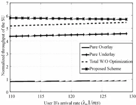
In Figure 4, the performance of the optimized access strategy, the pure overlay strategy, the pure underlay strategy and the overall throughput of the secondary network with and without optimization are compared. The underlay strategy can obtain more throughpu
e overlay strategy because we have assigned more po- wer for u
s
S . It should be remembered that the overlay
strategy avoids the coexisting time with the primary user, which has the least influence on the primary user. The proposed optimized access strategy maximizes the total throughput and has limited interference on the primary
Figur ed throughput of the secondary system
users
e 3. Normaliz , A and B.
Figur ed throughput of the secondary system
h with different access schemes. e 4. Normaliz
[image:5.595.60.289.82.228.2] [image:5.595.310.536.533.708.2]th
A ap B bp u s
I
g g
S
user, since the condition is always
guaranteed.
In Figure 5, the normalized throughput for the pure underlay and the proposed underlay strategies versus the access probability is shown. The value of the arrival rate of the user B, B is fixed at 115 ms. As mentioned in
Section 4, there is an unique optimal access probability that maximize the throughput.
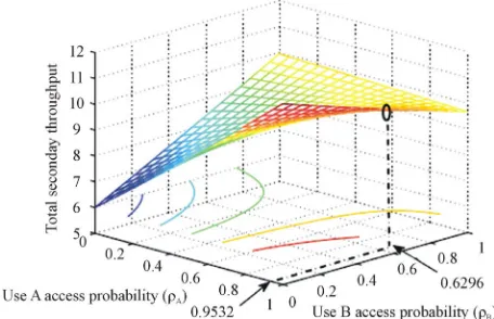
In Figure 6, the throughput is plotted versus the two access probabilities. When the throughput is at the worst case which equivalent to the overlay throughput. Accessibility of user A enhances the throu- ghput more than that of user B. This is because user A
of
0
A B
creats less interference on the primary user. The small circle on the graph shows the optimized value
9.78 s
R , note that
A B .To study the effect of changing the arrival rate of the far user A, B is fixed at 110 ms, while A is varied in Figure 7. Because of the nearness of user B where the probability to introduce interference on the primary is hight, B is always less than A. As A increases, both access pro bilities decrease to mitigate the inter-ba
bining these two It is assum that secondary users ference on the primary user. This degradation is more for the near user B.
7. Conclusion
The two dominant access schemes in the cognitive radio architecture, underlay and overlay, are studied. It is found by some literatures that these two schemes can make up with each other to enhance the system’s performance. This paper proposes a mixed access strategy com
[image:6.595.308.536.86.233.2]schemes. ed
Figure 6. Normalized throughput of the secondary system versus the access probabilities A, B.
Figure 7. The influence of far u er’s arrival rate on the access probabilities.
s
access the spectrum with certain access probabilities. It is focused on the service state and model the service state of the system as a continuous-time Markov chain. Finally, optimal access probabilities and optimal throughput for this mixed strategy are introduced in closed forms to maximize the overall capacity of the cognitive network. The simulation results show that the proposed access strategy can achieve much better performance for the secondary uses, compared with the single scheme strate-gies.
REFERENCES
[1] C. Cordeiro, K. Challapali, D. Birru and N. Shankar, “IEEE 802.22: The First Worldwide Wireless Standard
ore, 8-11 November 2005, pp. 328- Based on Cognitive Radio,” The First IEEE International Symposium on New Frontiers in Dynamic Spectrum Ac-cess Networks, Baltim
337.doi:10.1109/DYSPAN.2005.1542649
[image:6.595.310.537.277.453.2][2] M. Marcus, “Unlicensed Cognitive Sharing of TV Spec-trum: The Controversy at the Federal Communications Figure 5. Normalized throughput of the secondary system
[image:6.595.60.287.525.707.2]Commission,” IEEE Communication Magazine, Vol. 43,
No. 5, 2005, pp. 24-25.
doi:10.1109/MCOM.2005.1453413
[3] M. Khoshkholgh, K. Navaie and H. Yanikomeroglu, “Access Strategies for Spectrum Sharing in Fading Envi-ronment: Overlay, Underlay, and Mixed,” IEEE Journal on Mobile Computing, Vol. 9, No. 12, 2010, pp. 1780-
1793.doi:10.1109/TMC.2010.57
[4] X. Kang, Y. Liang, H. Garg and L. Zhang, “Sensing-Based Spectrum Sharing in Cognitive Radio Networks,”
IEEE Transac ology, Vol. 58, No.
8, 2009, pp. 46 VT.2009.2018258
tions on Vehicular Techn
49-4654.doi:10.1109/T
[5] D. Zhang, Z. Tian and G. Wei, “Spatial Capacity of Nar-rowband vs. Ultra-Wideband Cognitive Radio Systems,”
IEEE Transactions onWireless Communications, Vol. 7,
No. 11, 2008, pp. 4670-4680. doi:10.1109/T-WC.2008.070746
[6] D. Wong, A. Hoang and F. Chin, “Dynamic Spectrum Access with Imperfect Sensing in Open Spectrum Wire-less Networks,” Proceedings of IEEE Wireless Commu-nications and Networking Conference (WCNC), Las
Ve-gas, 31 March 2008-3 April 2008, pp. 2765-2770. [7] B. Wang, Z. Ji, K. Liu and T. Clancy,
“Primary-Prio-ritized Markov Approach for Dynamic Spectrum Alloca- tion,” IEEE Transactions on Wireless Communications,
Vol. 8, No. 4, 2009, pp. 1854-1865. doi:10.1109/T-WC.2008.080031
[8] H. Hu and Q. Zhu, “Dynamic Spectrum Access in Un-derlay Cognitive Radio System with SINR Constraints,”
Proceedings of the 5th International Conference on Wire-less Communications, Networking and Mobile Computing