© 2017, IRJET | Impact Factor value: 5.181 | ISO 9001:2008 Certified Journal
| Page 30
A STUDY OF BEHAVIOR OF RCC BOX CULVERT UNDER THE INFLUENCE
OF STATIC AND DYNAMIC LOADS IN ACCORDANCE WITH IRC
Mahesh D. Kakade
1, Rajkuwar A. Dubal
21
PG student, Department of civil (structural) engineering, JSPM’s RSCOE, Tathawade, Pune, Maharashtra, India
2Associate professor, Department of civil (structural) engineering, JSPM’s RSCOE, Tathawade, Pune,
Maharashtra, India
---***---Abstract -
Box culvert problem is a complicated example ofsoil structure interaction where the relative stiffness between the backfill soil and the culvert materials is critical factor in the load carrying capacity of culverts. Culvert is provided under earth embankment for crossing of water course like streams. across the embankment, as road embankment cannot be allowed to obstruct the natural water way This project deals with study of some of the design parameters of box culverts like effect of earth pressure and depth of cushion provided on top slab of box culverts and the relative study of box full and box empty conditions is done using finite element analysis tool ANSYS. The finite element model of ANSYS can be compared with numerical models as a plain strain problem. Furthermore box culvert with cushion or without cushion is
also compared for different cases.
Key Words: Box culvert, FEA, Ansys, IRC.
1. INTRODUCTION
Box Culverts consists of two Horizontal and two vertical slabs built monolithically which are ideally suited for a road or railway bridge crossing with high embankments crossing a stream with a limited flow. If the discharge in a drain or channel crossing a road is small, and if the bearing capacity of the soil is low, then the box culvert is an ideal bridge structure. The height of the vent generally doesn’t exceed 3 meters. Box culverts are economical due to their rigidity and monolithic action and separate foundation are not required because the bottom slab is resting directly on the soil, serves as raft. For a box culvert, the top slab requires to withstand the dead loads, live loads from moving traffic, earth pressure on sidewalls, water pressure from inside, and pressure on the bottom slab besides self weight of the slab. The structure is designed like a rigid frame using moment distribution method to obtain final distributed moments on the basis of the relative stiffness of the slab and vertical walls. A few things like depth of cushion, coefficient of earth pressure for lateral pressure on walls, width or angle of dispersion for live loads on box without cushion and with cushion for structural deformation are important items where opinion of the designers vary and therefore need to be studied in much detail. These affect the design significantly and therefore, required to be assessed correctly for designing a safe structure. Therefore an attempt is made to study with
cushion and without cushion for static and moving live load in box full and box empty conditions.
What is a Culvert?
Culvert is a tunnel structure constructed under roadways or railways to provide cross drainage or to take electrical or other cables from one side to other. The culvert system is totally enclosed by soil or ground.
Materials for Culvert Construction
Culverts are like pipes but very large in size. They are made of many materials like
I. Concrete
II. Steel III. Plastic IV. Aluminum
V. high density polyethylene
In most cases concrete culverts are preferred. Concrete culverts may be reinforced or non-reinforced. In some cases culverts are constructed in site called cast in situ culverts. Precast culverts are also available. By the combination above materials we can also get composite culvert types.
Types of Culverts
Following are the types of culverts generally used in construction:
Pipe culvert (single or multiple) Pipe Arch (single or multiple) Box culvert (single or multiple) Arch culvert
Bridge culvert
Pipe Culvert (Single or Multiple)
© 2017, IRJET | Impact Factor value: 5.181 | ISO 9001:2008 Certified Journal
| Page 31
flows very well. The diameter of pipe culverts ranges from 1meter to 6m. These are made of concrete or steel etc.
Pipe Arch Culvert (Single or Multiple)
Pipe arch culverts means nothing but they looks like half circle shaped culverts. Pipe arch culverts are suitable for larger water flows but the flow should be stable. Because of this arch shape fishes or sewage in the channel is easily carried to the outlet without stucking at the inlet or at the bottom of channel. This type of culverts can also be provided in multiple numbers based on the requirement. They also enhance beautiful appearance.
Box Culvert (Single or Multiple)
Box culverts are in rectangular shape and generally constructed by concrete. Reinforcement is also provided in the construction of box culvert. These are used to dispose rain water. So, these are not useful in the dry period. They can also be used as passages to cross the rail or roadway during dry periods for animals etc. Because of sharp corners these are not suitable for larger velocity. Box culverts can also be provided in multiple numbers if the width of channel is large.
Arch Culvert
Arch culvert is similar to pipe arch culvert but in this case an artificial floor is provided below the arch. For narrow passages it is widely used. The artificial floor is comprised of concrete and arch is also of concrete. Steel arch culverts are also available but very expensive so less used.
Bridge Culvert
Bridge culverts are generally provided on canals or
rivers and also used as road bridges for vehicles. For
this culvert a foundation has to be laid under the
ground surface. A series of culverts is laid and
pavement surface is then laid on top this series of
culverts. Mostly these are rectangular shaped culverts
and can replace the box culverts if artificial floor is not
necessary.
2. METHODOLOGY
2.1 Introduction
The finite element method (FEM) is the most popular simulation method to predict the physical behavior of systems and structures. Since analytical solutions are in general not available for most daily problems in engineering sciences numerical methods like FEM have been evolved to find a solution for the governing equations of the individual problem. Much research work has been done in field of
numerical modelling during last thirty years which has enabled engineers today to perform simulations close to reality. Nonlinear phenomena in structural mechanics like nonlinear material behavior, large deformations or contact problems have become standard modelling tasks. Due to a rapid development in the hardware sector resulting in more powerful processors together with decreasing costs of memory it is nowadays possible and easy to perform simulations even for models with millions of degrees of freedom. In a mathematical sense the finite element solution always just gives us an approximate numerical solution of the considered problem. Sometimes it’s not always an easy task for an engineer to decide whether the obtained solution is a good or bad one. If experimental or analytical results are available it is very easily possible to verify any finite element result. However, to predict any structural behaviour in a reliable way without experiments every user of a finite element package must have a certain background about the finite element method in general. In addition, he should also have fundamental knowledge of the applied software to be able to judge the appropriateness of the chosen elements and algorithms. This paper is has tried to show a summary of ANSYS capabilities to obtain results of finite element analyses as accurate as possible.
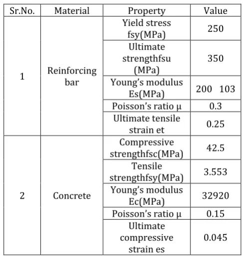
2.2 Materials properties
[image:2.595.311.555.487.745.2]The characteristics of the real properties of materials
are presented in Table 3.1 Materials properties of box
culvert were as follows.
Table -1 Material properties
Sr.No. Material Property Value
1 Reinforcing bar
Yield stress
fsy(MPa) 250
Ultimate strengthfsu
(MPa) 350
Young’s modulus
Es(MPa) 200 103
Poisson’s ratio µ 0.3
Ultimate tensile
strain et 0.25
2 Concrete
Compressive
strengthfsc(MPa) 42.5
Tensile
strengthfsy(MPa) 3.553
Young’s modulus
Ec(MPa) 32920
Poisson’s ratio µ 0.15
Ultimate compressive
© 2017, IRJET | Impact Factor value: 5.181 | ISO 9001:2008 Certified Journal
| Page 32
2.3 Material modeling
The definition of the proposed numerical model was made by using finite elements available in the ANSYS code default library. SOLID186 is a higher order 3-D 20-node solid element which represents quadratic displacement behavior. This element is defined by 20 nodes which have three degrees of freedom per node: translations in the nodal x, y, and z directions. The element supports plasticity, hyper elasticity, creep, stress stiffening, large deflection, and also large strain capabilities. It also has mixed formulation capability to simulate deformations of nearly incompressible elastoplastic materials, and fully incompressible hyper elastic materials. The geometrical representation of has been shown in SOLID186 fig 2.5.
This SOLID186 3-D 20-node homogenous/layered structural solid were adopted to discretize the concrete slab, which are also able to simulate cracking behavior of the concrete under tension (in three orthogonal directions) and crushing in compression, to evaluate the material non-linearity and also to enable the inclusion of reinforcement (reinforcement bars scattered in the concrete region).The element SHELL43 is defined by four nodes which have six degrees of freedom at each node. The deformation shapes are linear in both in-plane directions. The element allows for plasticity, creep, stress stiffening, large deflections, and large strain capabilities. The representation of the steel section has been made by the SHELL 43 elements, which allow the consideration of non-linearity of the material and show linear deformation on the plane in which it is present. CONTA174 is used to exhibit contact and sliding between 3-D "target" surfaces (TARGE170) and a deformable surface which is defined by this element. The element is applicable to 3-D structural and coupled field contact analyses. The geometrical representation of CONTA174 is show in fig 2.2. Contact pairs couple general axisymmetric elements with standard 3-D elements. A node-to-surface contact element represents contact between two surfaces by specifying one surface as a group of nodes. The geometrical representation of is show in TARGET 170 fig 2.3.
The TARGET 170 and C0NTA 174 elements were used
to represent the contact slab-beam interface. These
elements are able to simulate the existence of pressure
between them when there is contact, and separation
between them when there is not. The two material
contacts also take into account friction and cohesion
between the parties.
Fig.no.2.2
CONTA 174
Fig.no.2.3TARGET 170
Fig.no.2.4
Shell 43
© 2017, IRJET | Impact Factor value: 5.181 | ISO 9001:2008 Certified Journal
| Page 33
Fig. 2.6
Solid 186
2.4. Failure criterion
Two limits are established to define the ultimate load for each finite element investigation: a lower and an upper bound, corresponding to concrete compressive strains of 0.2%, and 0.35%, respectively. These two limits define an interval in which the composite beam collapse load is located. A third limit condition, hereinafter referred to as the stud failure point, can also be reached when the composite beam’s most heavily loaded stud reaches its ultimate load, as defined from the appropriate push-out tests. If the stud failure point is located before the lower bound of concrete (i.e., the corresponding load of the stud failure point is smaller than the lower bound load) then the mode of failure of the composite beam is considered as stud failure. Conversely, if the stud failure point is located after the upper bound of concrete, the mode of failure should be assumed as being concrete crushing. For the intermediate case, where the stud failure point lies between the lower and upper bounds of concrete, than the mode of failure could be either of the two. Therefore, the proposed finite element model is able to predict the failure modes associated with either slab crushing or stud failure.
Fig. no. 2.7
Constitutive relation for the steel of the
reinforcement
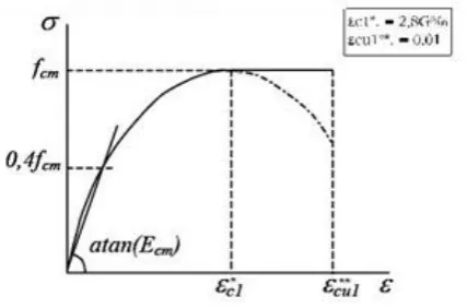
Fig. no. 2.8
Constitutive relation for the concrete
3. PROBLEM STATEMENT
Clear span: 3 m Clear height: 3 m
Top slab thickness: 0.42 m Bottom slab thickness: 0.42 m Side wall thickness: 0.42 m Unit weight of concrete: 24 kN/m3 Unit weight of earth: 18 kN/m3 Unit weight of water: 10 kN/m3
Co-efficient of earth pressure at rest: 0.5 Total cushion on top: 0.0 m
Thickness of wearing coat: 0.065 m Carriageway 2 lane divided
Concrete grade M25 = 25 Mpa Steel grade Fe 415 = 415 Mpa Modular ratio: 10
n (for depth of neutral axis): 0.294 j (for effective depth): 0.902
k (for moment of resistance): 1.105 Mpa
© 2017, IRJET | Impact Factor value: 5.181 | ISO 9001:2008 Certified Journal
| Page 34
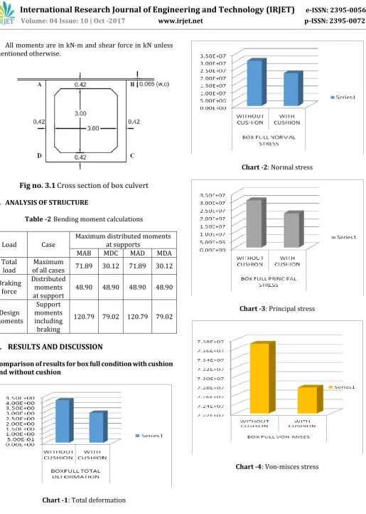
All moments are in kN-m and shear force in kN unless [image:5.595.43.559.42.765.2]mentioned otherwise.
Fig no. 3.1
Cross section of box culvert
4. ANALYSIS OF STRUCTURE
Table -2 Bending moment calculations
Load Case Maximum distributed moments at supports
MAB MDC MAD MDA
Total
load of all cases Maximum 71.89 30.12 71.89 30.12
Braking force
Distributed moments
at support 48.90 48.90 48.90 48.90
Design moments
Support moments including braking
120.79 79.02 120.79 79.02
5.
RESULTS AND DISCUSSION
Comparison of results for box full condition with cushion and without cushion
Chart -1: Total deformation
Chart -2: Normal stress
Chart -3: Principal stress
[image:5.595.70.286.139.279.2]© 2017, IRJET | Impact Factor value: 5.181 | ISO 9001:2008 Certified Journal
| Page 35
Chart -5: Shear stress6.
CONCLUSION
The total deformation for box full without cushion condition is more than box full with cushion condition.
The normal stress for box full without cushion condition is more than box full with cushion condition.
The maximum principle stress for box full without cushion condition is more than box full with cushion condition.
The equivalent stress for box full without cushion condition is more than box full with cushion condition.
The shear stress for box full without cushion condition is less than box full with cushion condition.
7.
ACKNOWLEDGEMENT
I express my sincere gratitude and respect to my project guide Prof. R. A. Dubal and Prof. G. R. Patil, Professor department of structure (Civil), Rajarshi Shahu college of Engineering, Pune for their valuable suggestions, timely support and encouragement. I thank them for numerous useful suggestions apart from valuable guidance to me.
I would like to convey my sincere gratitude to my friends, colleagues and all the staff members of department of structure (Civil) for their support and encouragement. The meaning of work is incomplete without paying regards to my respected parents and family whose blessings and continuous encouragement have shown me the path to achieve my goals.
REFERENCES
Sarah L. Orton, J. Erik Loehr, Andrew Boeckmann,;
and Garrett Havens, “Live-Load Effect in Reinforced Concrete Box Culverts under Soil Fill”, American Society of Civil Engineers, published in 2015
Neha Kolate, Molly Mathew, Snehal Mali, “Analysis
and Design of RCC Box Culvert”, International Journal of Scientific & Engineering Research, ISSN 2229-5518, Volume 5, Issue 12, December-2014
A. C. Lande, S. K. Kamane, S. A. Mahadik, “Finite Element Analysis of Box Culvert”, 3rd World Conference on Applied Sciences, Engineering & Technology 27-29 September 2014
Komal S. Kattimani, R. Shreedhar, “Parametric
Studies of Box Culverts”, International Journal of Research in Engineering and Science (IJRES) ISSN (Online): 2320-9364, ISSN (Print): 2320-9356, Volume 1 Issue 1, May. 2013
Anil K. Garg and Ali Abolmaali, “Finite-Element
Modeling and Analysis of Reinforced Concrete Box Culverts”, Journal of Transportation Engineering, Vol. 135, No. 3, March 1, 2009
B.N. Sinha & R.P. Sharma, “Rcc Box Culvert - Methodology and Designs Including Computer Method”, Journal of the Indian Roads Congress, October-December 2009
E. Awwad, M. Mabsout , S. Sadek , and K. Tarhini,
“Finite Element Analysis of Concrete Box Culverts”, American Society of Civil Engineers, published in 2000
Shad M. Sargand, Glenn A. Hazen, “Structural
Evaluation of Box Culverts”, Journal of Structural Engineering, Vol. 118, No. 12, December, 1992. ASCE, ISSN 0733-9445/92/0012-3297
IRC: 5 – 1998
IRC: 6 – 2000