GRID INTERFACED RENEWABLE ENERGY SOURCE TO IMPROVE
POWER QUALITY USING SAPF
V. Manimegalai
1, N. Senthilnathan
2,M. Sabarimuthu
31PG Scholar, Dept of EEE, Kongu Engineering College, Tamilnadu, India 2Professor, Dept of EEE, Kongu Engineering College, Tamilnadu, India 3Assistant Professor, Dept of EEE, Kongu Engineering College, Tamilnadu, India
---***---
Abstract –
The living standard demands excessive power from utility due to increasing population and depletion of fossil fuel resources. These issues leads to develop a new sources of energy ie, Renewable energy sources (RES). RES connected to the distributed system is termed as distributed generation (DG), which leads to power quality (PQ) issues such as distortion, irregularity unbalance etc. More usage of power electronics devices with renewable energy sources may reduce quality of power by injecting harmonics in the line. The power quality problem can be overcome by grid interfaced inverter control which compensates the PQ issues while integrating REU. The grid connected with renewable energy source has the capability of injecting active power to the grid, reduces source current distortion and reactive power compensation.Key Words: Renewable Energy, Distributed Generation, Power quality, shunt Active filter
1. INTRODUCTION
The living standard of energy demand increases day by day due to overgrowth of population. The fossil fuels is burned and supplied in order to cope up with this energy demand. But the usage of fossil fuels leads to air pollution, global warming etc. The extensive use of fuels increases the cost, as well demands in future. This makes to look over the alternate source ie., Renewable energy sources as the future energy solution for distributed generation. This paper represents the effective solution of shunt active power filter for eliminating the harmonics to maintain the quality of utility power supply. Passive filters are traditionally used but it has the major drawback which leads to resonance problem and poor dynamic performance. Active power filters gives best solution compared to conventional passive filters for the mitigation of harmonic and reactive power disturbance . Active power filters is the device which
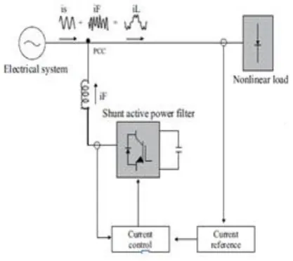
[image:1.595.312.521.419.605.2]generate the same amount of harmonic as generated by the load but 180° phase shifted. The harmonics inserted into the line are eliminated and utility supply become sinusoidal. RES is not connected directly to the grid instead it is connected to the grid interfaced inverter. DC link voltage capacitor is connected to grid interfaced inverter which play important role transferring the active power from RES to grid. Based on the control techniques, the inverter act and inject the compensating harmonics current.
Fig -1: Basic shunt active power filter
current, extraction methodology using adaptive detection algorithm that is able to extract the harmonic content from the load current. In [4], Iiango et al. proposed modified IcosΦ controller primarily based shunt active filter as an interface between renewable energy sources and grid. In [5],Weimin Chinese et al .proposed LLCL-filter-based grid-tied inverter that effectively will suppress the attainable resonances though the grid inductance varies during a wide selection. In [6], Joao Afonso et al. present a APF as a reliable and cost- effecient solution to power quality problems. In [7], Mukhtiar Singh et al. mentioned most advantages obtained from a unique control strategy for grid-interfacing inverters in distribution system. In [8], Jiang Zeng et al. proposed optimal voltage primarily vector based hysteresis current control methodology with constant switching frequency for Active power filter is used. In [9], Zubair Ahmed Memon et al. proposed a design of hybrid active filter to reduce current disturbance produced by power electronics based devices. . In [10], Sudheer Kasa et al. presents I cos ANFIS control primarily based Dynamic Active Power Filter (DAPF) to enhance the power quality of the grid at supply side. In [11], Roshan Haste et al. presents a control techniques of Grid interfaced inverter is done either individually or combined to overcome the unbalanced effects of all types of loads at distribution level. In [12], Vishnu Prasad et al. proposed grid connected PV system is implemented with adaptive HCC for inverter control. In [13], Sreya grace mathew, fossy mary chacko proposed a Hysteresis current control method to generate gate pulses which is used to compensate reactive power and current harmonics. In [14], Akshay S. Shirbhate, Prof.Suhas D. Jawal presents that shunt active filter is one the best configuration which can be used to compensate harmonic current, reactive power, neutral current unbalance current. In [15], Jain Sun proposed a impedance analysis based approach for multi-inverter system which mitigating resonance and other stability and power quality problems. In [16], Pichai Jintakosonwit, Hideaki Fujita et al. proposes cooperative control of multiple active filters based on voltage detection for harmonic damping throughout a distribution system level.
2. PROPOSED WORK
[image:2.595.310.543.381.553.2]In this paper, the proposed work consists of renewable energy source connected to the dc link of the grid interfacing inverter as shown in Figure 1. The connected load is non-linear characteristics which generates harmonics in the line. In this system, grid interfaced inverter acted as a shunt active power filter. Solar (PV) is not connected directly to grid common coupling point (CCL) instead it is connected through the shunt active power filter. The quality of power is maintained by shunt active power filter which is controlled by PI controller. Shunt active power filter inject the current based on the control algorithm. Shunt active filter compensate load current harmonics by injecting equal-but opposite harmonic compensating current and compensate the reactive power at common coupling point (CCL). By compensating reactive power, it brings unity power factor and also supply more active power from the solar energy source to the grid.
Fig -2: Block diagram
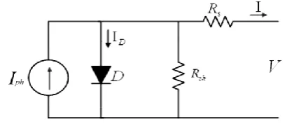
2.1 Modeling of PV model
The chosen model is the single diode model with series and parallel resistors for greater accuracy is shown in figure 2.
[image:2.595.315.517.663.753.2]Using the below equation the PV are modeled.
Photocurrent IPh:-
Iph=(Iscr+ki*(TK-Tref))*(λ/1000) (1)
Module Saturation Current I0:-
Irs=Irr*(T/Tr)3*exp(q*Eg/(k*A)*((1/Tr)-(1/T)))) (2)
Module Output Current IPV:-
ID=np*Iph-np*I0*(exp(q*(Vpv+IpvRs/(k*T*A*ns))-1) (3)
2.2 Control Algorithm of Grid Interfaced Inverter From the source voltage (Vabcs),the maximum voltage Vm is calculated. The actual voltage is compared with reference voltage and it is passed through a first PI controller. The current from the PI controller is multiplied with unit vector component, which generates inphase reference current (Isad, Isbd, Iscd).The maximum voltage (Vm) is compared with reference voltage (Vmref) and it is passed through a second PI controller, which results as a current. This current from PI controller is multiplied by unit vectors to generate the quadrature reference current (Isaq, Isbq, Iscq). The addition of inphase reference current & quadrature reference current, it generates the reference currents (Iabcref).
The reference current, is compared with the actual source current and it is given to hysteresis current controller (HCC). HCC generates switching pulses for grid interfacing inverter. Based on the control technique, the shunt active filter inject the current. This current cancels the harmonic of source current and compensates the reactive power.
Fig -4: Flow chart for unit template algorithm
3. RESULT &DISCUSSION 3.1 System without Filter
[image:3.595.329.554.566.735.2]In proposed method, a system is carried out without Filter. It is observed that the current waveform is non sinusoidal due to harmonics in the line. This is mainly due to non linear load and power electronics components connected across it.
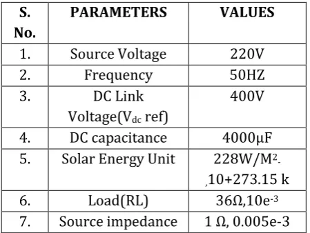
Table -1: System Parameters for Simulation
S. No.
PARAMETERS VALUES
1. Source Voltage 220V
2. Frequency 50HZ
3. DC Link
Voltage(Vdc ref)
400V
4. DC capacitance 4000μF
5. Solar Energy Unit 228W/M
2-,10+273.15 k
6. Load(RL) 36Ω,10e-3
Fig -5: Source Voltage (without filter)
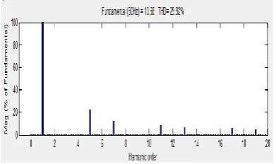
[image:4.595.64.260.427.543.2]Fig -6: Source & load Current (without filter) In FFT analysis, Total Harmonics Distortion of source and load current without filter is 29.92% is shown in figure 5.
Fig -7: FFT Analysis (source & load current)
3.2 System with Filter
RES is connected to the inverter through dc link capacitor.The inverter will act based on control Algorithm.From Algorithm, the reference current is generated which is sinosoidal waveform is shown in figure 12. The reference current generated is compared with source current. and the compensating current are shown in figure 6.
Fig -8: Reference Current (Iasref, Ibsref, Icsref)
Fig -9: Compensating current (Ia, Ib, Ic )
3.2 DC link voltage
[image:4.595.311.534.462.723.2]The DC link voltage across the capacitor (Vdc) is around 400V is shown in figure 7.
Fig -10: DC Link Voltage
Fig -12: Source Current
Fig -13: DC Link Voltage
The distorted source current waveform is turned into a sinusoidal current with amplitude of 10 A is shown in figure 9. The THD of source current is reduced from 29.87% to 2.02%. The THD value of system with and without filter is shown in table 2.
Fig -14: Load Current
Fig -15: Active and Reactive Power from Grid
Fig -16: Active and Reactive Power to Load
[image:5.595.35.551.43.449.2]Fig -17: Active and Reactive Power Injected to Grid
Fig -18: Power factor
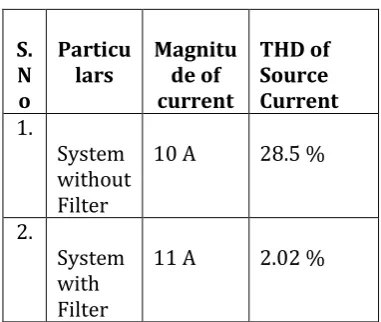
Table -2: THD Values of System (with and Without Filter)
T he THD value of current is reduced to 2% The active power from the load is nearly 3900 W and reactive power to the load is 1900 W is shown in the figure 13. Active and Reactive Power Injected to Grid is almost 0 W (active) &1900 W (reactive)is shown in figure 14. The Active & reactive power from the load is subtracted with the active & reactive power injected to the grid. Therefore Active & reactive power from grid is around 3900W and 0W is shown in the figure 12.
S. N o
Particu
lars Magnitude of
current
THD of Source Current 1.
System without Filter
10 A 28.5 %
2.
System with Filter
[image:5.595.331.522.503.664.2]Since the reactive power is compensated it leads to unity power factor is shown in figure 15.
4. CONCLUSION
This Paper has proposed an efficient unit template algorithm of grid interfacing inverter to eliminate the current harmonics, and to compensate the reactive power demand at common coupling point. It has been found that total harmonic distortion of grid current reduced from 29.92% to 2.02% and it results in unity power factor.
REFERENCES
[1] Abhayrajsinh J. Rana, Mahesh H. Pandya, et al,
“Application of Unit Template Algorithm for Voltage Sag Mitigation in Distribution Line Using D-STATCOM,” Energy Efficient Technologies for Sustainability ICEETS, pp: 756-761, 2016
[2] Uffe Borup,“Sharing of Nonlinear Load in
Parallel-Connected Three- Phase Converters,” IEEE Transactions On Industry Applications, Vol. 37, No.6, pp:1-7, 2001.
[3] Utkal Ranjan Muduli and Ragavan. K, “Dynamic
Modeling and Control of Shunt Active Power Filter,” vol. 11, pp: 5720-5727,2014
[4] Ilango K, et al, “Modified ICosФ Controller for Shunt
ActiveFilter Interfacing Renewable Energy Source and Grid,”AASRI Conference on Power and Energy Systems, Vol. 17 pp: 62-68,2012.
[5] Weimin Wu, et al, “A robust passive damping
method forLLCL-filter-based grid-tied inverters to minimize the effect of grid harmonic voltages,” IEEE transactions on power electronics, Vol. 29, No. 7, pp: 3279-3289, 2014.
[6] Joao Afonso, et al, “Shunt Active Filter for Power
Quality Improvement,” International Conference UIE, pp: 683-691,2001.
[7] Singh Mukhtiar, Chandra Ambrish, Varma Rajiv K,
“Grid interconnection of renewable energy sources at the distribution level with power-quality improvement features,” IEEE Transactions Power Delivery’,vol 20, No.3, pp:307-315, 2011.
[8] Zeng J, Yu C, Qi Q, Yan Z, “A novel hysteresis current
control for active power filter with constant frequency,” Elsevier, Electric Power System research, Vol.68, No:1, pp:75–82, 2004
[9] Zubair Ahmed Memon et al, “Design of Three-Phase
Hybrid Active Power Filter for Compensating the Harmonic Currents of Three-Phase System ,” Mehran University Research Journal of Engineering & Technology, Volume 31, No. 2, pp:347-354, ,2012.
[10] Sudheer Kasa, Prabhu Ramanathan, Sudha
Ramasamy, D.P.Kothari, “Effective grid interfaced
renewable sources with power quality
improvement using dynamic active power filter,”Elsevier, Vol 2 , pp: 150-160,2016.
[11] Roshan Haste, Avinash Matre, “Power Quality
Improvement in Grid Connected Renewable Energy Sources at Distribution Level,” International Conference on Circuit, Power and Computing, Vol:4, No:1, pp: 27-34, 2014.
[12] Vishnu Prasad, Jayasree P R, Sruthy V, “Active
Power Sharing and Reactive Power Compensation in a Grid-tied Photovoltaic System,” Elsevier, Vol.3, No.5, pp: 1-7, 2016.
[13] Sreya grace mathew, fossy mary chacko, “ power
quality improvement in a grid connected renewable energy system” International Journal of Electrical, Electronics and Data Communication, ISSN: 2320-2084 Volume-2, Issue-10, Oct.-2014.
[14] Akshay S. Shirbhate, Prof.Suhas D. Jawal “Power
Quality Improvement in PV Grid Connected System by Using Active Filter”, International Journal of Advanced Research in Electrical, Electronics and Instrumentation Engineering. Vol. 5, Issue 2, February 2016.
[15] Jain Sun , “Power Quality in Renewable Energy
Systems – Challenges and Opportunities”, European Association for the Development of Renewable Energies, Environment and Power Quality ,International Conference on Renewable Energies and Power Quality,March2012.
[16] Pichai Jintakosonwit, Hideaki Fujita, Hirofumi
Akagi , et al “Implementation and Performance of Cooperative Control of Shunt Active Filters for Harmonic Damping Throughout a Power Distribution System”IEEE Transactions on industry applications, vol. 39, No. 2 ,pp:556-564,march/april 2003.
[17] Vishnu Prasad, Jayasree P R, Sruthy V , “Active
Power Sharing and Reactive Power Compensation in a Grid-tied Photovoltaic System”, Elsevier,Vol 3 No 5, pp: 1-7, march 2016.
[18] S.Syed Ahmed, N. Sreekanth, ‘Power Quality