© 2017, IRJET | Impact Factor value: 5.181 | ISO 9001:2008 Certified Journal | Page 644
Adaptive Sliding Mode-MRAS Strategy for Sensorless Speed
Control of SPIM Drives
L. Sunil
11
PG Scholar, Dept. Of Electrical & Electronics Engineering, JNTUACEA, Ananthapuramu, A.P., India
---***---Abstract –
The objective of this paper is to providesensorless control of Single Phase Induction Motor (SPIM) drives to improve the rotor speed and the stator currents. In order to achieve this high performance, adaptive Super Twisting Algorithm (STA) is used. The proposed method for the estimation of speed is based on Sliding Mode Model Reference Adaptive System (SM-MRAS) observer. An adaptive time varying switching gain is designed and adopted in order to cancel disturbance and uncertainties. To improve the estimator generated signal a discrete low pass filter is used. It represents a very simple design process compared to other chattering reduction methods as adding an observer. By using the Lyapunov approach the stability of the SM-MRAS speed estimation algorithm is proved. Simulation results prove the effectiveness of the proposed sensorless speed control algorithm.
Key Words
:
Adaptive Sliding Mode-MRAS, Chattering, Super twisting algorithm, Single Phase Induction Motor (SPIM), Sensor-less sliding mode control.1. INTRODUCTION
Variable Speed Drives (VSDs) applications are vastly used in the industry to control a wide range of speed and torque for machines, manufacturing process, pumps etc. VSDs have been integrated in several applications to accomplish one or more of the following objectives: energy saving, mechanical vibrati on
reduction, power factor improvement, better
coordination of motion on various shafts and production gains. In particular, the use of VSDs becomes recommended in many applications employing the Single Phase Induction Motors (SPIMs), such as blowers, washing machines, air conditioner, fans, compressors and pumps. Therefore, diverse control approaches have been proposed along the last years to drive the SPIM speed. Nowadays, Field-Oriented Controlled (FOC) induction motors are widely adopted to obtain high-dynamic performance in drive systems. Advanced controls such as Indirect Rotor Field- Oriented Control (IRFOC) need specific knowledge of the rotational speed information for feedback control. This information can be obtained via a mechanical sensor. Nowadays, many efforts are made to implement the sensorless control strategy to simplify the control structure and cut down the cost. In several applications different methods are applied to sensorless speed control of Induction
© 2017, IRJET | Impact Factor value: 5.181 | ISO 9001:2008 Certified Journal | Page 645 parameter variations can degrade speed control
performances. Thus, some kind of parameter adaptation is required in order to obtain high-performance sensorless vector control drive. In paper [15], an observer based on two independent linear control systems provides the estimations of the rotor flux from the measurements of the stator currents and voltages is proposed. Consequently, this approach uses machine model equations that depend on some motor parameters; as a result an ordinary parameter variation can affect the estimator performances. However, in contrast to the above works; this paper adopts for the first time a Sliding Mode Model Reference Adaptive System (SM-MRAS) rotor speed observer. The proposed approach does not suffer from the problem of pure integration and low sensitivity to the system parameter variations. Consequently, the proposed SM-MRAS observer is capable of delivering high performances for a wide speed range, including very low speeds.
Conjointly, the SMC has been recognized as an appropriate technique for controlling nonlinear systems with uncertain dynamics, parameter variations and disturbances, thanks to its invariance and order reduction properties and simplicity design [17]-[18]. The main drawback of this technique is the well known chattering phenomenon caused by the excitation of un-modeled dynamics and sensor noise. Chattering may appear for on/off switches controlled systems if switching frequency is limited or the switching gain is inadequate. Particularly, in any SMC implementation, the chattering phenomenon causes harmful effects such as torque pulsation, current harmonics and acoustic noise [19], [20]. Mathematical analysis and numerical simulation have been performed to demonstrate the efficiency on chattering reduction of switching gain adaptation methods [19]-[22]. As well, it was noted that the gain adaptation techniques were not enough satisfactory when singly used in classical SMC algorithms. Hence, their experimental implementation associated with the use of a smoothing continuous function or LPF has been recommended in many advanced recent works [22], [23].
Therefore, this paper investigates the design and the DSP full implantation of an efficient robust sensorless speed vector control strategy devoted to drive a SPIM based SM technique and free of chattering. The synthesis of SOSM controllers based on an adaptive super twisting algorithm to control the speed and the stator currents, and a MRAS rotor speed estimation algorithm based sliding mode adaptation mechanism. Concerning the SM-MRAS rotor speed estimation, the adaptation mechanism is made by the association of an equivalent and discontinuous estimation laws. The equivalent law is synthesized from the desired sliding mode surface constraints; whereas a special care is given to the construction of switching gain of the discontinue term. Thus, a time varying switching
gain followed by a discrete Low Pass Filter (LPF) is considered for practical implementation. The proposed switching gain is defined to guaranties accurate rotor speed estimation and a good disturbances rejection. As it will be illustrated, this combination represents an excellent solution for chattering suppression. Finally, the SM-MRAS stability is verified via the Lyapunov approach.
2. SPIM State space model
The input–output SPIM state space model in a stationary reference frame (denoted by the superscript in term of the stator current and rotor flux can be given by
[
] *
+ [
] *
+ [
]
(1)
Where
= [
]
T
,
=
[
]
T
,
=
[
]
In addition, the matrix
and
B
are
© 2017, IRJET | Impact Factor value: 5.181 | ISO 9001:2008 Certified Journal | Page 646
(
)
(
)
It is seen that there is an asymmetry in the model. Such an appropriate variable transformation of the stator variables is adopted in order to carry out a symmetric model for the FOC strategy use
{
{
With
:
K
=
.
While the mechanical and the electromagnetic torque expressions are, respectively, given by
(
(2)
(
)
(3)
Where, , , , , and are the
axes voltages, currents, and fluxes of the stator and rotor in the stationary reference frame; , , , ,
and denote the stator and rotor self and mutual inductances; , , and denote axes stator and
rotor resistances; , , , and are the rotor angular frequency, the slip angular frequency, the electromagnetic
torque, and the load torque; , , and are the friction
coefficient, the total inertia, and the pole pairs number.
2a. IRFOC strategy of SPIM
The block diagram of the proposed IRFOC control strategy associated to the SPIM is illustrated in Fig.2.1 The relationship between rotor-flux components and the stator currents in the synchronous reference frame (denoted by the superscript d, q) is expressed as follows:
*
+
=
[
] *
+ [
] [
]
where
*
+
**
++
[
]
[
]
=
[
]
And
The
matrix performs the coordinate
transformation from the reference frame aligned along with the stator-flux vector to the stationary reference frame. We choose a reference frame linked to the rotor flux, so that the d-axis coincides with the desired direction of the rotor flux
(
=
and
= o
)
.
The expression (2.10) can be decomposed into two equations= -
+
(4)
=
(5)
The expression for the torque can be calculated be
(6)
© 2017, IRJET | Impact Factor value: 5.181 | ISO 9001:2008 Certified Journal | Page 647
3. Second order sliding mode speed and current
controllers design
The proposed SOSMCs speed and current controllers design is based on the so-called STA. This algorithm ensures that the states can slide on the chosen sliding surface S. The control law is composed of two terms formulated around the sliding variables. The first one is the integral of a discontinue function, whereas the second term represents a continuous function to alleviate the chattering effect.
Let us consider the following sliding surfaces:
[
] [
] [
] [
] [
]
(7)
Taking in consideration that the electromagnetic torque reference represents the speed controller output in the IRFOC strategy, the first derivative forms of the errors are , as shown at the top of the next page. Adopting the following partial feedback linearization equation:
[
] [
]
with
(8)
Therefore, the second errors derivative forms can be expressed as
[
̈
̈
̈
]
=
[
] [
]
(9)
With
[
]
[
(
)
(
)
]
_
[
]
[
]
(
[
]
[
]
[
]
)
[
]
(10)
We suppose that the terms
,
G
1,
G
2
,
and
G
3 are
bounded by known positive constants as
{
Adopting the following proposed control law:
{
|
|
(
(
|
|
(
)
(
|
|
(
(
Where , and are the tuning controller parameters, which are positives constants respecting the following equations:
{
((
© 2017, IRJET | Impact Factor value: 5.181 | ISO 9001:2008 Certified Journal | Page 648 used method for chattering reduction would be efficient if
it may conduct the switching gain amplitude to converge to a small value and this without affecting the subsistence of sliding mode. To take care of probably parameter or load variations and the chattering reduction accentuation, a way can be considered resulting in the adjustment of the control gains according to the instantly sliding surface value and to its variation in time
{
(
(
The adopted adaptive switching gains expressions are
{
{
√
(
Where
,
,
, and
are arbitrary positive constants. Then, the adaptive STA will enforce the considered sliding surface and its first derivative to tend to zero in finite time, even at the presence of unknown disturbances and uncertainties with unknown boundary. To realize this time varying control gain, an integrator operator with external rest signal is performed. This procedure allows us keeping a small gain value when the state trajectory is at immediate proximity of the desired values. The designed structure has the advantage to derive the time varying gain to the fixed minimal value after disturbances cancellation. Otherwise, the incessant switching gain increasing may lead for chattering occurrence or estimator divergence.4. SM-MRAS ROTOR SPEED ESTIMATOR DESIGN
The MRAS algorithm for speed estimation is based on the fact that there are two ways to estimate the rotor fluxes from the basic equations of the SPIM in the stationary reference frame.
From the stator equations
[
(
]
(11)
[
(
)
]
(12)
From the rotor equations
(13)
(14)
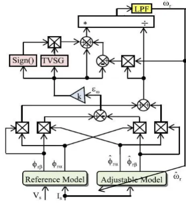
[image:5.595.320.508.188.394.2]Notice that the stator equations are independent of the rotor speed and are used as the reference model. The rotor equations are dependent on the rotor speed and thus can be used as the adjustable model.
Fig 4 Speed estimator block diagram
The main idea of the MRAS is to compare the outputs of the two models and to adjust the value of rotor speed in order to minimize the resultant error. The adjusted value is the speed generated from the error between rotor fluxes observed. Fig. 4 gives the structure of the proposed
SM-MRAS speed estimation. Where, the tuning signal is the
input of the designed sliding mode adaptation mechanism. This will delivers the value of the estimated rotor speed used to actualize the adjustable mode.
4.1 Design of SM-MRAS Algorithm
A classical speed tuning signal is adopted and
is expressed by the following equation:
(15)
Defining a sliding surface S proportional to the previous speed tuning signal as
with k>0 (16)
When the desired state spaces reach the switching surface and stay there, this gives
© 2017, IRJET | Impact Factor value: 5.181 | ISO 9001:2008 Certified Journal | Page 649 Therefore, the error dynamic can be described by the
following equation, meaning that it will be forced to exponentially tend to zero:
(18)
Differentiating (18) yields
̂
⏞
̂
⏞
Substituting the derivative estimated terms by their expressions, this equation can be arranged as
̂
(19)
With
̂
̂
[(
̂
)
(
̂
)
]
(20)
(21)
The rotor speed can be estimated using the following proposed adaptation control law made up equivalent term and nonlinear term:
̂
(22)
Equalizing (18) and (19), the equivalent term can be carried out and expressing the rotor estimated speed value when the state variable holds on the sliding surface
(23)
(
(24)
4.2 Stability proof
Defining the following candidate Lyapunov function V as:
(25)
The stability of the proposed sliding mode control law describing the adaptation mechanism can be easily established. Then, the first time derivative expression of the candidate Lyapunov function is:
(
̇
̇
) (26)
Taking into account expressions (19) and substituting the equivalent and nonlinear law terms by their expressions, we get:
̇
-k
2S
2-k
𝛥
1| |
(27)
Since k and G1 are positives then, the derivative form is always negative, therefore the proposed control law is stable and the switching function S is for all time attractive and is reached in finite time.4.3 Estimator Chattering Reduction
The overall rotor speed estimator block diagram with a TVSG as designed is given by Fig. 4. The adaptive switching gain principle used in the above paragraph is the same used in the design of the speed estimator adaptive switching gain. For proper rotor speed estimation, the generated signal is followed by a discrete LPF. The use of an LPF is a recognized practical method to get a continuous signal from the generated signal.
The designed LPF recurrent expression is
( ( ( (
(28)
Where
ζ
is a tuning positive constant filter parameter satisfying the following condition:ζ=
(29)
Where is the sampling time and
is the considered
time constant of the LPF. The speed is estimated very accurately by making as small as possible, but larger than the sampling time. Then, the suppression chattering objective can be completely accomplished.
[image:6.595.313.561.626.748.2]5. Simulation model and Results
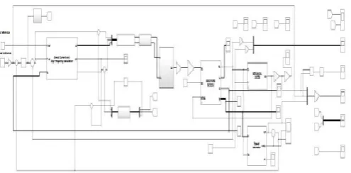
© 2017, IRJET | Impact Factor value: 5.181 | ISO 9001:2008 Certified Journal | Page 650 The simulation block diagram consists of mainly
induction motor modeling block, voltage source inverter block and sliding mode model reference adaptive system block. The output of the inverter is given to the motor and when it receives below the rate speed then inverter currents and motor voltages are applied to
sm-mras scheme. From this speed is estimated and it is compared with step reference speed and error is calculated. From that control signal is obtained which is given to the voltage source inverter. Based on control signal voltage source inverter adjust the firing pulses to obtained the reference speed.
Fig. 5.2 rotor speed (rpm)
Fig. 5.3 Electromagnetic torque (Nm)
[image:7.595.75.540.88.755.2]Fig. 5.4 Speed sliding surface (Sw)
[image:7.595.327.540.99.508.2]Fig. 5.5 Sliding gain
Fig. 5.6 Direct and quadratic flux (wb)
Fig. 5.7 Stator currents (A)
© 2017, IRJET | Impact Factor value: 5.181 | ISO 9001:2008 Certified Journal | Page 651 coupled to the SPIM and piloted with a control unit. An
isolation amplifier block is calibrated and then used to measure the main and auxiliary windings currents and the SPIM speed.
The simulation is achieved using
MATLAB/SIMULINK software. It operates at a frequency of 250 MHz. To generate the PWM signals, we adopted a sinusoidal PWM technique with a switching frequency of 3 kHz and a dead time of 2 μs for the three-leg inverter. The sampling time of the control algorithm is fixed to 60 μs.
The SPIM started without load torque, and then a nominal load torque is applied at 6 s and removed at 16 s. In the proposed sysytem SPIM is operating at nominal speed. The proposed SOSM speed controller and the speed SM-MRAS estimator exhibit good tracking performances and fast response without steady error and with neglected overshoot (<3%).
6. CONCLUSIONS
An adaptive sliding-mode observer for speed sensorless FOC of SPIM drive has been presented. A robust SOSM speed controller, two SOSM controllers to drive the stator currents, and a SM-MRAS adaptation mechanism for SPIM speed estimation has been designed. In addition to its chattering elimination capability, the use of an adaptive STA in control law design guaranties fast responses and a short time convergence. Owing to a very simple online self adaptive switching gain, the proposed SOSM control law does not require the knowledge of uncertainties bounders, to guarantee the desired performances. The main advantage of the proposed SM-MRAS speed estimator is that it does not necessitate a sublimate algorithm for parameter estimation to have accurate speed estimation even at very low speed range. The SM-MRAS algorithm stability was proved by Lyapunov approach. Finally, and by means of simulation results, it has been shown that the designed sensorless speed SPIM drive, exhibits a very good tracking trajectory error and high performance speed estimation.
REFERENCES
[1] R. Saidura, S. Mekhilef, M. B. Ali, A. Safari, and H. A. Mohammed, “Applications of variable speed drive (VSD) in electrical motors energy savings,” Renew. Sustain. Energy Rev., vol. 16, no. 1, pp. 543–
550, 2012.
[2] R. Rocha, L. de Siqueira Martins, and J C. D. de Melo, “A speed control for variable-speed single phase induction motor drives,” in Proc. IEEEISIE, Jun. 2005, pp. 43–48.
[3] M. Jemli, H. Ben Azza, M. Boussak, and M. Gossa, “Sensorless indirect stator field orientation speed control for single-phase induction motor drive,” IEEE Trans. Power Electron., vol. 24, no. 6, pp. 1618–
1627, Jun. 2009.
[4] M. B. R. Corrêa, C. B. Jacobina, A. M. N. Lima, and E. R. C. da Silva, “Rotor flux oriented control of a single phase induction motor
drive,” IEEE Trans. Ind. Electron., vol. 47, no. 4, pp. 832–841, Aug.
2000.
[5] M. B. de Rossiter Corrêa, C. B. Jacobina, E. R. C. da Silva, and A. M. N. Lima, “Vector control strategies for single-phase induction motor drive systems,” IEEE Trans. Ind. Electron., vol. 51, no. 5, pp. 1073–
1080, Oct. 2004.
[6] G. J. Rubio, J. M. Cañedo, A. G. Loukianov, and J. M. Reyes, “Second order sliding mode block control of single-phase induction motors,”
in Proc. 18th IFAC World Congr., Sep. 2011, pp. 1–6.
[7] B. Akin, U. Orguner, A. Erask, and M. Ehsani, “A comparative study on non-linear state estimators applied to sensorless AC drives: MRAS and Kalman filter,” in Proc. 30th Annu. Conf. IEEE Ind.
Electron. Soc., vol. 3. Nov. 2004, pp. 2148–2153.
[8] M. Boussak, “Implementation and experimental investigation of sensorless speed control with initial rotor position estimation for interior permanent magnet synchronous motor drive,” IEEE Trans. Power Electron., vol. 20, no. 6, pp. 1413–1421, Nov. 2005.
[9] G. H. B. Foo and M. F. Rahman, “Direct torque control of an IPMsynchronous motor drive at very low speed using a sliding-mode stator flux observer,” IEEE Trans. Power Electron., vol. 25, no.
4, pp. 933–942, Apr. 2010.
[10] H. Kim, J. Son, and J. Lee, “A high-speed sliding-mode observer for the sensor-less speed control of a PMSM,” IEEE Trans. Ind. Electron.,
vol. 58, no. 9, pp. 4069–4077, Sep. 2011.
[11] M. Cirrincione, M. Pucci, G. Cirrincione, and G. A. Capolino, “A new TLS based MRAS speed estimation with adaptive integration for high performance induction motor drives,” IEEE Trans. Ind. Appl.,
vol. 40, no. 4, pp. 1116–1137, Jul./Aug. 2004.
[12] R. Cardenas, R. Pena, J. Clare, G. Asher, and J. Proboste, “MRAS observers for sensorless control of doubly-fed induction generators,” IEEE Trans. Power. Electron., vol. 23, no. 3, pp. 1075–
1084, May 2008.
[13] S. Vaez-Zadeh and H. S. Reicy, “Sensorless vector control of singlephase induction motor drives,” in Proc. 8th ICEMS, vol. 3. Sep.
2005, pp. 1838–1442.
[14] H. Ben Azza, M. Jemli, M. Boussak, and M. Gossa, “High performance sensorless speed vector control of SPIM Drives with on-line stator resistance estimation,” Simul. Model. Pract. Theory, vol. 19, no. 1, pp.
271–282, Jan. 2011.
[15] M. Caruso, V. Cecconi, A. O. Di Tommaso, and R. Rochat, “Sensorless variable speed single-phase induction motor drive system,” in Proc.
IEEE ICIT, Mar. 2012, pp. 731–736.
[16] M. Comanescu and L. Xu, “Sliding-mode MRAS speed estimators for sensorless vector control of induction machine,” IEEE Trans. Ind.
Electron., vol. 53, no. 1, pp. 146–153, Feb. 2006.
[17] J. Yan, H. Lin, Y. Feng, X. Guo, Y. Huang, and Z. Q. Zhu, “Improved sliding mode model reference adaptive system speed observer for fuzzy control of direct-drive permanent magnet synchronous generator wind power generation system,” IET Renew. Power Generat., vol. 7, no. 1, pp. 28–35, Feb. 2013.
[18] C. Y. Chen, “Sliding mode controller design of induction motor based on space-vector pulse width modulation method,” Int. J. Innovative
Comput., Inf. Control, vol. 5, no. 10, pp. 3603–3614, Oct. 2009.
[19] A. Levant, “Chattering analysis,” IEEE Trans. Autom. Control, vol. 55,
no. 6, pp. 1380–1389, Jun. 2010.
[20] M. L. Tseng and M. S. Chen, “ Chattering reduction of sliding mode control by low pass filtering the control signal,” Asian J. control, vol.
12, no. 3, pp. 392–398, May 2010.
[21] A. Levant, “Higher-order sliding modes, differentiation and output feedback control,” Int. J. Control, vol. 76, no. 9–10, pp. 924–941,
© 2017, IRJET | Impact Factor value: 5.181 | ISO 9001:2008 Certified Journal | Page 652
[22] I. Boiko and L. Fridman, “Analysis of chattering in continuous sliding-mode controllers,” IEEE Trans. Autom. Control, vol. 50, no. 9,
pp. 1442–1446, Sep. 2005.
[23] Y. Shtessel, F. Plestan, and M. Taleb, “Lyapunov design of adaptive super-twisting controller applied to a pneumatic actuator,” in Proc.
18thIFAC World Congr., Sep. 2011, pp. 3051–3056.
[24] Y. B. Shtessel, J. A. Moreno, F. Plestan, L. M. Fridman, and A. S. Poznyak, “Super-twisting adaptive sliding mode control: A Lyapunov design,” in Proc. 49th IEEE Conf. Decision Control, Atlanta,