© 2018, IRJET | Impact Factor value: 6.171 | ISO 9001:2008 Certified Journal | Page 1669
AN AUTOMATIC TECHNIQUE OF INBUILT HYDRAULIC JACK SYSTEM IN
FOUR WHEELER:- ARISING APPROACH
RAVINDRA KUMAR SINGH
1, PRATHU SINGH
2, AJEET SINGH GAUTAM
31
Assistant Lecturer, Department of Mechanical Engineering, Dayalbagh Educational institute, Agra, India
23
students, Department of Mechanical Engineering, Dayalbagh educational institute, Agra, India
---***---Abstract –
This paper is about the new automatic techniqueof inbuilt hydraulic jack system. Whenever the tyre failure is occurred in the vehicle then to lifting the vehicle from ground surface is the very difficult think for human being. And also huge human effort required and more time taking process. There, this inbuilt hydraulic jack system helps to lift the vehicle from the ground instead of conventional mechanical jack, and saves the time and excess effort. It is fitted on the vehicle chases. This inbuilt hydraulic technique can be quickly operated by automatic function buttons on the board panel of the vehicle. Main parts of this project is hydraulic jack, master cylinder, valves, manifold, oil reservoir. the arrangement of this technique are as follows, the hydraulic jack will be mounted on the near of the suspension system(springs) of the each wheel of the vehicle with the help of fasteners, then the inside valve of the hydraulic jack to be jointed with manifold through the small hydraulics tubes and outlet valve remain closed. and this manifold is attached with manifold and manifold is attached with oil reservoir. the all tubes are joint with ball valve and all valves good sealed manifold or master cylinder are joint with non return valve. The using importance of non return valve, it allows medium to flow in only one direction of hydraulic oil. That’s why here pressure conditions may otherwise cause reversed flow.
Key Words
:
1.hydraulic jack 2.Master cylinder 3.incompressible hydraulic oil 4.pascal’s law 5.Ball valve & non-return valve.
1. INTRODUCTION
Inbuilt hydraulic jack system is based on the principle of Pascal’s law. Hydraulics is mechanical function that operates through the force of liquid pressure. In hydraulics based systems mechanical movement is produced by contained, pumped liquid typically through cylinders moving pistons. Several upstarts relates to hydraulic system and more especially, to an inbuilt hydraulic jack system. Most of the vehicles are lifted by using screw jack. This needs high man power and consumes a lot of time. Various types of jack or lift devices has been installed on for lifting the vehicle. Conventionally we have always used a separate jack for each of 4 wheels; in steed here we have the jacks permanently installed on the vehicle. It is an object of innovation to provide ideal jack system that can be operated by driver from inside the car. It is also an object of innovation to provide an ideal hydraulic system which is operated by cam mechanism which actuates hydraulic jack which will lift the
vehicle. It is a device which will be used in future to tire changes purposes. When tire gets punctured we need to change the tire and with the help of this system, vehicle lift by a side automatically with little chores.
1.1 Features of Inbuilt hydraulic jack system
Hydraulic jack used on engine uplift has similar parts to other hydraulic jacks, major disparity is that these jacks are lengthy in height, so that the ram can lift the boom of a hoist in a greater height. The hydraulic jack consists of a cylinder, where the hydraulic fluid is held, around the cylinder is an oil chamber. Oil is used as a hydraulic fluid, because it also lubricates other parts of the jack. Inside the cylinder is a ram which is moved up or down by increasing or decreasing the oil pressure inside the cylinder. On the bottom of the ram inside the cylinder is a piston, which is properly sealed, to not let the pressure to bypass on the other side. On top of the ram a boom of the hoist is attached, so pumping the jack will raise the boom. There are multiple smaller copper washers, o-rings and sealing gaskets inside the jack to properly seal the oil, so the jack does not start to leak oil while lifting heavy loads. On the side of the jack is a pumping system that moves oil from one cylinder to other. The pumping system consists of a pump cylinder, a handle socket, a handle, which is inserted into the handle socket and hand powered to apply pressure inside the cylinder, and other small rings, pins, links and steel balls to cover the pump cylinder and washers. All in all, hydraulic jacks are pretty simple devices when looking at their construction, but they are capable to lifting very large amounts of weight, applying relatively small amount of force to them.
1.2 Pascal’s law for hydraulic jack
© 2018, IRJET | Impact Factor value: 6.171 | ISO 9001:2008 Certified Journal | Page 1670 pressure is the same as that on the first piston. This effect is
exemplified by the hydraulic jack, based on Pascal’s principle.
1.3 Uses of hydraulic jack/ cylinder in this
prototype
A jack is a instrument that uses pressure to raise up the heavy loads. In the seminal state procedure with which pressure is applied varies, depending on the specific type of jack, but is typically a screw thread or a hydraulic cylinder. Jacks can be classifying based on the type of force they employ: mechanical or hydraulic. Mechanical jacks, such as car jacks and house jacks, lift heavy equipment and are rated based on lifting capacity (for example, the number of tons they can lift). Hydraulic jacks tend to be stronger and can lift heavier loads higher, and include bottle jacks and floor jacks. The hydraulic fluid is incompressible and using a pump plunger is forced into the cylinder of the jack. Oil is used because of its stable and self lubricating nature. When the plunger pulls back, oil is drawn out of the reservoir and it goes inside the pump chamber. When the plunger moves forward, the oil is pushed back into the cylinder. This oil movement builds up pressure in the cylinder. And it is this pressure which leads to the working of the hydraulic jack. It also finds usage in workshops and also lifts elevators in low and medium rise buildings.
2. Literature background behind the inbuilt
hydraulic jack system:-
The literature background behind the inbuilt hydraulic jack system is that the most case study has done on the automatic hydraulic jack to making easily operated repaired the damaged and punctured and dissolution conditions of the wheel of the car for to change .if we consider a problem which is mostly happens in our daily life, while a disabled person ,women and old person is driving a car, immediately car's tyre gets punctured and it also gets breakdown conditions then these all are unable to change the tyre of the care with the help of mechanically jacks and conventionally jacks, in this condition the inbuilt hydraulic jack system helps them, pressing the button on the control board of the car then respectively the wheel will lift up from the earth ground which one pressed by them. Now we can change the punctured and solve the breakdown conditions. Now a day if we will see that every person wants to very high comforts for their body. it show that either increasing levels of technology efforts being put to increase the comfort and safety. Dr. Ramachandra C G, Krishna Pavana In his project said that main intention is to reduce the manual work and save time during the replacement of the failed tyre. To validate our point to overcome the difficulties of the above said problems, an inbuilt jacks have been designed and fabricated which is assembled on the vehicle. With the help of the existing brake pad and fluid arrangement of the braking system we incorporate the jack into to chassis of the vehicle with a set of unions, ball valves, master cylinder,
five-way directional control valve, separated by a piping arrangements lifts the incorporated jack to action desired without raising any sweat of the driver.
2.2 General requirement of inbuilt hydraulic jack
system:-
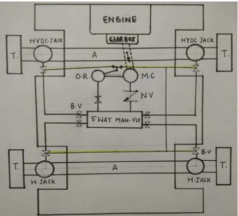
[image:2.595.316.554.386.602.2]We know that mechanical and screw jacks required more effort than in built hydraulic jack, and hydraulic jack required less human effort and less power consumption. It inbuilt hydraulic jack system can be operated by control board of the car to seat inside it. This technique is very useful for women and old people’s .Because these all are unable to operate mechanical jack by manually. Inbuilt Hydraulic jack has less number of moving parts in comparison of mechanical jack .That is why it has low maintenance. It is capable to lift up many tons of loads. Inbuilt hydraulic jack system has existing good properties to suitable for uneven surface. Inbuilt hydraulic is automatic system it gives the highly comfort, this is very high usable, convenient and valuable devices for women and old persons. Because here all mechanical jacking operations done automatically without manually effort. In other words it can be operated from within the vehicle by means of a control panel of the vehicle. It has low failure chance.
Fig -1: line diagram of inbuilt hydraulic jack system.
Main parts of this prototype:-
1. Hydraulic jack-Hyd. Jack 2. 5-way valve manifold 3. Ball valve- B.V 4. Non- return valve-N.V 5. Compressible oil tubes-C.O.T 6. Master cylinder-M.C
7. Oil reservoir- O.R 8. Engine
© 2018, IRJET | Impact Factor value: 6.171 | ISO 9001:2008 Certified Journal | Page 1671
1. MASTER CYLINDER:-
The master cylinder can be rigidly named as heart of the hydraulic braking system, because the pressure necessary for operating the graces as well as well as the hydraulic jacks is developed in this cylinder. There are two main chambers viz. the fluid reservoir and compression chamber in which the piston operates. The fluid in the reservoir compensates for any change in the fluid volume in the pipelines due to temperature variations and to some extent due to leakage. To prevent leakage there are rubber seals on both ends of the piston in the compression chamber. The reduced diameter region of the piston is always surrounded by the fluid. A rubber boot covers the push rod end of the cylinder to prevent the dirt from entering inside. Towards the brake lines side of the compression chamber, there is a fluid check valve with a rubber cup inside. It serves to retain the residual pressure in the brake lines even when the brakes are released.
2. HYDRAULIC JACK:-
Hydraulic cylinders get their power from pressurized hydraulic fluid , which is typically oil. The hydraulic cylinder consists of a cylinder barrel, in which a piston connected to a piston rod moves back and forth. The barrel is closed on each end by the cylinder bottom (also called the cap end) and by the cylinder head where the piston rod comes out of the cylinder. The piston has sliding rings and seals. The piston divides the inside of the cylinder in two chambers, the bottom chamber (cap end) and the piston rod side chamber (rod end). The hydraulic pressure acts on the piston to do linear work and motion. Flanges, trunnions, and/or clevises are mounted to the cylinder body. The piston rod also has mounting attachments to connect the cylinder to the object or machine component that it is pushing.
3. FIVE WAY MANIFOLD VALVE:-
The body of the valve is made of carbon steel of cast iron . The exterior and interior are cylindrical in shape. The interior is well ground for good seating of the plug. A hole is body cover or plate, which is placed below it and is fastened by screw after the plug is placed in the body. It has an inlet port on its port on its circumference at the top. The body plate has markings indicating the direction of the part lead i.e., right front jack, left front jack, fight rear jack, left jack and brakes. The operating handle is fixed to the plug by threads and a check nut so as to fix the handle in the direction of outlet part of the plug. This means that when the handle is in the directions of the left front jack marking of the cover plate. It will operate the left front jack, when the brake pedal is operated.
4. Ball valve:-
A ball valve is a form of quarter-turn valve which uses a hollow, perforated and pivoting ball (called a "floating ball")
to control flow through it. It is open when the ball's hole is in line with the flow and closed when it is pivoted 90-degrees by the valve handle. The handle lies flat in alignment with the flow when open, and is perpendicular to it when closed, making for easy visual confirmation of the valve's status.
3. Design of prototype:-
1. Hydraulic cylinder or jack, Cylinder barrel, Cylinder base or Cap, Cylinder head, Piston,
2. five-way directional control valve 3. Master cylinder
4. Non return valve 5. Ball valve
6. Hydraulic fitting and pipes 7. Chassis.
4.Working procedure of inbuilt hydraulic jack
system:-
© 2018, IRJET | Impact Factor value: 6.171 | ISO 9001:2008 Certified Journal | Page 1672 not the on the ball valve, the oil cannot be going into the
hydraulic jack. Then pressurized oil goes into the hydraulic jack through the inlet valve, the plunger of hydraulic jack is come out in the outside direction and plunger reaches the ground surface and the car’s chassis lift up on which side hydraulic jack is fitted This is the whole process is used to lift up the vehicle’s chassis. When all breakdown conditions have solved, then we on the ball valve to release the hydraulic jack pressure. Which is fitted on the respectively hydraulic jack, then the plunger reaches initial state and vehicle gets their neutral position. This is the whole working procedure of the inbuilt hydraulic jack system.
5. ADVANTAGES:-
The maintenance of the vehicle will be very easy. The servicing of the vehicle will be easy and cheap. Reduces human effort at large limit.
Can be operated even when the vehicle is not in starting condition.
The servicing of vehicle will be easy and cheap. Time saving of maintenance.
The maintenance of vehicle will be very easy and cheap.
This type of system is very useful for ladies and old people since during the problem of puncher of tyres, they can easily change the wheel.
This is also very useful for heavy vehicles such as trucks and buses, since there is a common problem of breaking leaf spring plates, this system will help in changing of leaf spring plates.
A single person can go on a long drive without worrying about getting stuck in the way.
They generally suffer from less damage due to hard parts rubbing together.
In hydraulic jack use fluids to transfer energy, fluids work better then solids as they can take different shapes.
This is suitable for uneven surfaces
6.DISADVANGES OF INBUILT HYDRAULIC JACK
SYSTEM:-
Cost will increase slightly. System required maintenance also.
Weight of vehicle will increase in the small amount. This jack is required more storage space and it can
be quite heavy.
7.FUTURE SCOPE OF INBUILT HYDRAULIC JACK
SYSTEM:-
The arrangement of inbuilt hydraulic jack system is designed for small car in this project work, but this arrangement can be widely use in future for heavy vehicles also by making some small modifications in current project.
8.CALCULATIONS AND DESIGN CONCIDERATIONS
OF THIS PROTOTYPE:-
Design of Hydraulic Jack System
Unaided weight of the car = 12.3 kg Weight on each wheel= 3kg Dimensions of pipe: Outer dia. Of pipe = 8mm Inner dia. Of pipe = 5mm
Specification of master cylinder
Diameter of the master cylinder = 1.2 cm = 12 mm Area of master cylinder = d2 = (12)2 A1= 114 mm2
Specifications of hydraulic cylinder
Outer diameter of cylinder = 30 mm Inner diameter of cylinder = 20 mm Diameter of the piston = 20 mm Stroke = 50mm
Pressure range =1.5-8kgf/cm Overall Length = 191mm Piston Material = Magnetic Body Material = Stainless Steel Piston Rod Material = Stainless Steel Rod Dia. = 8mm
Rod Thread Size = M8 x 1.25" Rod Thread Length = 18mm
Distance the larger piston moves
D2=F1 D1/F2
Where, F1 = force of the small piston, in pounds D1 = distance the small piston moves, in inches D2 = distance the larger piston moves, in inches F2 = force of the larger piston, in pounds
Design of Piston
We know that cylinder’s inner diameter is equal to piston’s outer diameter so piston outer diameter is 20mm. Generally piston’s are made from MILD STEEL & SUITABLE MATERIAL.
Design of Piston Rod
Material strength EN9 = 1750 kg/cm2 P=0.785×20×20×1750
P=549500kg/mm
Design of hydraulic unit
By Pascal’s law, =
𝐹 = 𝑃 𝐴
© 2018, IRJET | Impact Factor value: 6.171 | ISO 9001:2008 Certified Journal | Page 1673
1’st
Author
Photo
Force required at the working piston:F = P x A
= 0.3861 114 mm2 F = 45N
Therefore the force to be applied at the working piston is 45 N, which is 10 times lesser than the weight to be lifted.
An inbuilt hydraulic jack system can be easily attached to all currently manufacture automobile chassis.
9. CONCLUSION OF THIS PROTOTYPE:-
An inbuilt hydraulic jack system can be easily attached to all currently manufacture automobile chassis and frames. There is a master cylinder which produces the high pressure this highly pressure reaches to the hydraulic jack through five way manifold, non return valve and ball valve. The system operates on the hydraulic power and engine power. This arrangement has many advantages such as maintenance and servicing of vehicle. With the help of this system the driving of vehicles will be easy especially for ladies and disabled persons. Arrangement is also very useful for heavy loading vehicles and a single person can go on a long drive. The estimated costs are for making prototype but, if it is mass produced the cost can be considerably reduced. It is very convenient system and its use will be very popular if any entrepreneur’s introduced the system in the market. The system operates on the hydraulic power. This inbuilt hydraulic jack arrangement has many advantages such as maintenance and servicing of vehicle. It reduce the security tension and easy to implement. Quick lifting is possible and Suitable for heavy load for about 120kg or 1440N. The force to be applied at the working piston is 12 times lesser than the weight to be lifted. With the help of inbuilt hydraulic jack system the driving of vehicles will be easy.
REFERENCES:-
1. A Textbook of Machine Design by R.S.Khurmi & J.K.Gupta.
2. Rajmohan G, Jazim Haris, Mohamed Shafin: ‘Inbuilt lifting arrangements for heavy vehicles.
3. www.google.com.
4. Mohammed Abuzaid, Mohammad Hasnain: Inbuilt hydraulic jack in automobile vehicles.
5. Q.S. Khan, “Study of hydraulic seals”, Fluid Conductor and Hydraulic Oil, Volume-6, 1998.
6. www.mechengg.net.
7. http://www.hitech.in/control_valves.
8. Vickers, “Industrial hydraulics manual”, second edition 1989.
9. G. K. Patel Reference No. : 37s1373: A case study on implementation of hydraulic jack to heavy loaded vehicles.
10. A textbook on Fluid mechanics and hydraulic machines by R K bansal.
11. www.globalspec.com
BIOGRAPHIES:-
RAVINDRA KUMAR SINGH
He has been an assistant lecturer in DEI Technical college since 2003. He has been teaching Engineering drawing, lab of refrigeration and air conditioning and hydraulic and hydraulic machines. His research interests are engineering drawing and CAD/CAM. His knowledge of engineering drawing proved fruitful in the research process.
PRATHU SINGH
Born on 12th August 1999, he is final year student of diploma in mechanical
engineering at DAYALBAGH
EDUCATIONAL INSTITUTE, Agra, India. He did his internship at ATUL ENGINERING UDYOG. There he acquired knowledge about various manufacturing processes related to casting & mounding carried out at industrial scale. His interest areas include thermal engineering , refrigeration and air conditioning and manufacturing processes.
AJEET SINGH GAUTAM
Born on 5th March 2000, he is final year student of Diploma in mechanical
engineering at DAYALBAGH