© 2018, IRJET | Impact Factor value: 6.171 | ISO 9001:2008 Certified Journal | Page 3757
Simulation & Hardware Implementation of APFC Meter to Boost Up
Power Factor Maintain by Industry.
Bhargav Jayswal
1, Vivek Khushwaha
2,Prof. Pushpa Bhatiya
31.2 B. E Electrical Engineering, Vadodara Institute of Engineering, Vadodara, Gujarat, India 3: Assistant Professor in Electrical Engineering Department, Vadodara Institute of Engineering,
Vadodara, Gujarat, India
---***---Abstract -
In recent years, the power quality of the acsystem has become great concern due to the rapidly increased numbers of electronic equipment, power electronics and high voltage power system. most of the commercial and industrial installation in the country has large electrical loads which are severally inductive in nature causing lagging power factor which gives heavy penalties to consumer by electricity board. This situation is taken care by APFC.Automatic Power factor correction is the capacity of absorbing the reactive power produced by a load. In case of fixed loads, this can be done manually by switching of capacitors, however in case of rapidly varying and scattered loads it becomes difficult to maintain a high power factor by manually switching on/off the capacitors in proportion to variation of load within an installation. This drawback is overcome by using an APFC panel. In this paper measuring of power factor from load is done by Arduino and trigger required capacitors in order to compensate reactive power and bring power factor near to unity.
Key Words: Power factor, reactive power Arduino, Penalty, capacitor bank, APFC Meter.
1. INTRODUCTION
The low power factor leads to the increase in the load current, increase in power loss, and decrease in efficiency of efficiency of the overall system. In previous various method use for power factor correction in all this method, the switching of the capacitor is manual. In this paper we are using a method of the reactive power compensation by capacitor switching with automatic control using Arduino.
1.1 POWER FACTOR THEROY
A) Types of power:
Active Power: The actual amount of power being used, or dissipated, in a circuit is called the true power. It is measured in watts and is symbolized mathematically by the capital letter P. Active power is a function of circuit’s dissipative element, such as resistances(R).
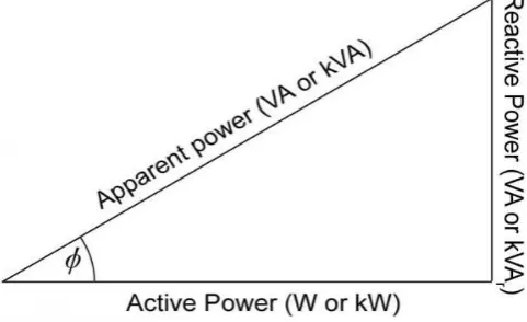
Reactive Power: Reactive loads such as inductors and capacitors dissipate zero power, but the fact that they drop voltage and draw current gives the perception that they do dissipate power. This “dissipated power” is called the reactive power and is measured in Volt-Amps-Reactive (VAR) and is
[image:1.595.312.553.240.387.2]symbolized by the capital letter Q, and it is the function of circuit’s reactance (X).
Figure 1: Power Triangle
Apparent Power: The combination of the active and reactive power is called apparent power. It is the product of a circuit’s voltage and current, without reference to phase angle. Apparent power is measured in Volt-Amps (VA) and is symbolized by the capital letter S. Apparent power is a function of a circuit’s total impedance (Z).
1.2 Power Factor
Power factor is the ratio between the active power (kW) to the total apparent power (kVA) consumed by an a.c. electrical equipment or a complete electrical installation.
𝑃𝑜𝑤𝑒𝑟𝐹𝑎𝑐𝑡𝑜𝑟 (𝑃𝐹) = 𝐴𝑐𝑡𝑖𝑣𝑒𝑝𝑜𝑤𝑒r / Apparent power
It is a measure of how efficiently electrical power is converted into useful work output. The ideal power factor is unity, or one. Anything less than one means that extra power is required to achieve the actual task at hand.
© 2018, IRJET | Impact Factor value: 6.171 | ISO 9001:2008 Certified Journal | Page 3758 Basically AC power circuits, have resistive loads (like
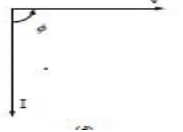
[image:2.595.57.240.283.415.2]heaters) or inductive loads (like choke) or capacitive loads (like power supplies). Depending upon the loads the current phasor can be in-phase with voltage, lagging the voltage or leading the voltage.
Figure 2: Phasor diagram for purely resistive load
For purely resistive load current is in phase with the voltage. Therefore, phase difference ø=0˚. Thus giving power factor, cosø=1. Hence the power factor for purely resistive load is unity.
Figure 3: Phasor diagram for purely inductive load.
In a purely inductive circuit, the current lags the voltage. Therefore, the phase difference between current and voltage ø=90˚. Hence power factor is lagging.
In a purely capacitive circuit, the current leads the voltage therefore the phase difference between current and voltage ø=90˚.thus the power factor is said to be leading.
1.3 Causes of Low Power Factor
Low Power factor is caused by inductive loads. Inductive loads require the current to create a magnetic field that produces the desired work. The result is an increase in reactive and apparent power and a decrease in the power factor, or efficiency, of a system. Since the power factor is defined as the ratio of KW to KVA, we see that low power factor results when KW is small in relation to KVA. An
inductive load includes transformers, induction choke, and induction generators, high intensity discharge lighting. These inductive loads constitute your distribution system. This increase in reactive power results in large angle between KW and KVA. This large angle decreases the power factor. The efficiency of inductive equipment and system power factor will vary depending on its manufacturer, design, size and age. Most inductive equipment has a nameplate with operating data, including its power factor at rated load.
1.4 Power factor correction
Capacitive power factor correction is applied to circuits which include induction choke as a means of reducing the inductive component of the current and thereby reduce the losses in the supply. There should be no effect on the operation of the choke itself. An induction choke draws current from the supply that is made up of resistive components and inductive components. The current due to the leakage reactance is dependent on the total current drawn by the choke, but the magnetizing current is independent of the load on the choke. The magnetizing current will typically be between 20% and 60% of the rated full load current of the choke. The magnetizing current is the current that establishes the flux in the iron and is very necessary if the choke is going to operate. The magnetizing current does not actually contribute to the actual work output of the choke. It is a catalyst that allows the choke to work properly. The magnetizing current and the leakage reactance can be considered as the passenger components of current that will not affect that the power drawn by the choke, but contribute to the power dissipated in the supply and distribution system.
1.5 Disadvantages of Low Power Factor
i) Large Line Losses (Copper Losses): Line Losses is directly proportional to the square of current „I2‟ therefore, larger the current, the greater the line losses.
ii) Large kVA rating and size of electrical equipment’s: Power factor is inversely proportional to the kVA i.e. CosФ = kW / kVA Therefore, lower the power factor, the larger the kVA rating of machines also, the larger the kVA rating of machines, the larger the size of machines, the larger the cost of machines.
iii) Greater conductor size and cost: In case of low power factor, current will be increased, thus to transmit this high current, we need the larger size of conductor. Also, the cost of large size of conductor will be increased.
iv) Poor voltage regulation and large voltage drop:
Voltage drop = V = IZ.
[image:2.595.105.227.490.611.2]© 2018, IRJET | Impact Factor value: 6.171 | ISO 9001:2008 Certified Journal | Page 3759 v) Low efficiency:
In case of low power factor, there would be large voltage drop and large line losses and this will cause the system or equipment efficiency too low. Due to low power factor, there would be large line losses; therefore, alternator needs high excitation, thus, generation efficiency would be low.
vi) Penalty from electric power supply
Electrical power Supply Company imposes a penalty of power factor below 0.95 lagging in electric power bill. So industries must improve power factor above 0.95.
2) PROPOSED SYSTEM
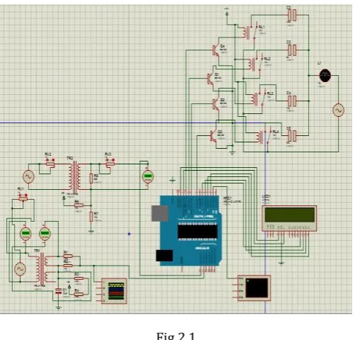
Arduino is used in this project as a central processing unit to calculate the power factor and to switch the capacitors. The working of this project is explained with the help of the below block diagram.
Fig 2.1
It uses a potential transformer to supply the voltage to the Resistor divider network (like zero voltage crossing circuit), which detects the zero crossing of the voltage wave form. These voltage pulses from the operational amplifier are applied to the Arduino as interrupt signals. Similarly, a current transformer is used here to give the current wave to the Resistor divider network wherein the operational amplifier output is enabled for every 10 ms by comparing the zero position of the current with the predefined setting. This signal is also applied to the Arduino as an interrupt signal. The Arduino finds time elapse between these two interrupts and substitutes it in a certain equation for calculating the power factor. If this power factor value is above 0.96 then the Arduino doesn’t send any command signals to the relay driver to switch the capacitors on. But, if it is less than 0.96, then the Arduino sends command signals to the relay driver so that the capacitor bank on. Therefore,
these capacitors reduce the lagging nature of the load by giving leading currents to it. The number of capacitors’ switching depends on the value of the power factor – very low power factor needs all the capacitor, whereas high power factor needs none of those.
[image:3.595.37.288.313.553.2]2.1 Hardware
Fig 2.2
The proposed work can be explained in the form of block diagram as shown in figure 2.2 It comprises of following 7 blocks
CT & PT
Comparator unit
Resistor divider network Arduino
LCD
Relay
Capacitor bank
2.1.1 Voltage & current measurement unit
Current transformer (CT) is connected series with line, and Potential transformer (PT) is connected parallel with supply line. CT & PT are used to step down the voltage and current for resistor divider network.
2.1.2 Comparator unit
© 2018, IRJET | Impact Factor value: 6.171 | ISO 9001:2008 Certified Journal | Page 3760 2.1.3 Resistor divider network
Resistor voltage dividers are commonly used to create reference voltages, or to reduce the magnitude of a voltage so it can be measured. A simple example of a voltage divider is two resistors connected in series, with the input voltage applied across the resistor pair and the output voltage emerging from the connection between them.
2.1.4 LCD
An Arduino program must interact with the outside world using input and output devices that Communicate directly with a human being. One of the most common devices attached to an Arduino is a Liquid crystal display. Some of the most common LCDs connected to the Arduino are 16x2 and 20x2 displays.
2.1.5 Relay
Relay outputs are provided which operate to connect or disconnect the capacitor banks depending upon of the power factor conditions.
2.1.6 Capacitor bank
Capacitor bank is an assembly of number of capacitors which are used to contribute KVAr in the electrical system and finally improve the power factor. Shunt capacitors bank are arrangements of series/paralleled connected units.
2.1.7 SOFTWARE REQUIREMENT Arduino sketch software
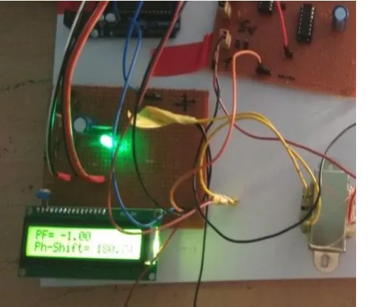
[image:4.595.308.560.73.310.2]2.2 RESULTS Inductive Load
[image:4.595.36.297.515.731.2]Fig.2.3: Before PFC
Fig.2.4: After P.F.C.
3 CONCLUSIONS
It can be concluded that power factor correction technique can be applied to the industries, power systems and also house hold to make them stable and due to that the system becomes stable and efficiency of the systems as well as the
The authors can acknowledge any person/authorities in this section. This is not mandatory.apparatus increases. When the detected power absorbed by the load is greater than the compensator rating, the power factor will not be corrected to unity but certainly, will be improved and the apparent power supplied by the AC supply will be reduced. They achieve better power quality by reducing the apparent power drawn from the AC supply and minimizing the power transmission losses. Hence the efficiency of the systems as well as the apparatus increases.
REFERENCES
[1] Sapna Khanchi & Vijay Kumar Garg, “Power Factor Improvement of Induction Motor by using Capacitors”, International Journal of Engineering Trends & Technology (IJETT), Volume 4, issued 7-July 2013.
[2] Jain Sandesh, Thakur Shivendra Singh and Phulambrikar S.P., “Improve Power Factor and Reduce the Harmonic Distortion of the System”, International Journal of Advanced Research in Computer Science and Software Engineeriong. Volume 1(5), issued November 2012.
© 2018, IRJET | Impact Factor value: 6.171 | ISO 9001:2008 Certified Journal | Page 3761 Engineering Technology and Advanced
Engineering”, Volume 2, issue 2 February 2012.
[4] Abhinav Sharma, Shavet Sharma, Parveen Lehana & Saleem Khan, “To Analysis the Effect of Combination Load on the Power Factor” , International Journal of Advanced Research in Computer Science and Software Engineering , volume 3, issue 8, August 2013.
[5] Anant Kumar Tiwari, “Automatic Power Factor Correction Using Capacitive Bank”, International Journal of Engineering Research and Applications, Volume 4, issued February 2014.
BIOGRAPHIES
Bhargav Jayswal, I am a final year student of Electrical. Dept.in Vadodara institute of engineering, Vadodara.
Vivek Khushwaha, I am a final year student of Electrical. Dept.in Vadodara institute of engineering, Vadodara