© 2018, IRJET | Impact Factor value: 6.171 | ISO 9001:2008 Certified Journal | Page 1912
Analysis and Design of Segmental Box Girder Bridge
MD TAUHEED REYAZ
1, SYEDA NIKHAT FATHIMA
21
Lecturer, Dept of Civil Engineering, HMS Rural Polytechnic, Karnataka, India
2
Assistant professor, Dept of Civil engineering, HMS Institute of technology Karnataka, India
---***---Abstract -
A bridgemay be ameans thatbythata road,railway oralternativeservice is carried overassociate degree obstacle like a stream,depressionand alternativeroad or railway line, either with no intermediate support or with solely a restricted range of supports at convenient locations. Strength, safety and economyarea unitthe3key optionsthat can'tbe neglected before theculminationofsorts ofbridges. Whereasdecidingthe kindsof bridge, spans andalternative parametersarea unitto be studied fastidiously to fulfillthe favorableconditions.
The design of aroutebridge is criticallysmitten bystandards and criteria. Naturally, the importance ofroutebridges in a veryfashionabletransitwould implya groupof rigorousstyle specificationsto confirmthe protection, quality and overall price of the project. This work discusses the comparative analysis of2standardsspecificallyAASHTO and IRC followed in construction of bridge superstructures subjected to load of seriousvehiclesfor 2sorts of examplesspecifically,beamwith single celland 4cell and comparison has been given..the look customaryof Bharat, IRC was followed instyleof Box girder superstructures subjected to IRCcategoryAA loading In load combination, AASHTO codes have takenadditional issueof safety than IRC. Analysis isdisbursed victimization the Csi Bridge. The parametersthought-abouttogiftthe responses of beambridgesspecifically, longitudinal stresses atthe highest and bottom, shear, torsion, moment, deflection and first harmonicof2sorts ofbeam bridges. Shear-z, torsion, moment-y impact on beam owing to IRC loading is additional as compared to AASHTO loading, i.e., vehicle loadthoughtin IRC as compared to AASHTO Itmeans thatthoughtof impactthink aboutAASHTO isadditionalcompared to IRC.
1.INTRODUCTION
Bridges square measure outlined as structures that square measure provided a passage over a spot while not closing manner below. They will be required for a passage of railway, roadway, pathway and even for carriage of fluid, bridge web site ought to be therefore chosen that it offers most business and social edges, efficiency, effectiveness and equality. Connects square measure nation’s life savers and spines inside the occasion of war. Spans symbolize goals and desires of mankind. They traverse boundaries that partition, bring people, groups and countries into nearer proximity. They abbreviate separations, speed transportation and encourage trade. Bridges square measure symbols of humanity’s heroic struggle towards mastery of forces of nature and these square measure silent monuments of mankind’s unconquerable can to achieve it. Bridge construction constitutes associate importance component in
communication and is a crucial consider progress of civilization, bridges stand as tributes to the work of civil engineers.
In order to supply safer and larger speed of traffic, the route is made as straight as potential Box girders, have gained wide acceptance in super highway and bridge systems owing to their structural potency, higher stability, unstableness, economy of construction and pleasing ,aesthetics. In US Bridge Engineers utilize the code of AASHTO "American Association of route {|expressway |freeway| motorway| pike| through way super highway| |thruway| highway| main road} and Transportation Officials"; this code will be embraced for style of the expressway spans with unique needs. Thus, Indian extension engineers look for guidance from the IRC (Indian Road Congress) typical to attempt to the arranging but The AASHTO common place Specification is adopted by several countries because the typically accepted code for bridge styles.
Box girder bridges are terribly unremarkably used. It’s a bridge that has its main beams comprising of girders within the form of hollow boxes. The create shaft usually incorporates of pre-focused on solid, steel or steel concrete. As appeared in Figure 1.1a create support crosses area could take the state of single cell (one box), different spines (separate boxes), or multi-cell with a standard base edge (nonstop cells) the container shaft span accomplishes its soundness in the fundamental because of 2 key components: structure and pre-focused on tendons.
© 2018, IRJET | Impact Factor value: 6.171 | ISO 9001:2008 Certified Journal | Page 1913 Segmental bridge construction is additionally reduces the
essential thinking of style engineers.
For style of fundamental street and Railway Bridge superstructures there are a few codes utilized round the world and a large portion of the nations have their own particular code figuring on the characteristic conditions and in this way the nearby natural components, similar to the unsteady impacts, critical destruction, noteworthy snow, precipitous bundle, varying sorts of auto utilized in nation and so forth. Indian scaffold engineers elude IRC (Indian Road Congress) ordinary for the auxiliary style. amid this study 2 box-support cross-segments were planned with very surprising cross segment i)Pre focused on solid box bar with four cells, ii) Pre-focused on solid box pillar with single cell. The look parameters were unbroken same for each of the cross-sections.
Moving load as per IRC6: 2000 were thought off or each the cross wise and normal moving load IRC category AA was applied. Comparison was done between the results of each the box-girder cross-sections.
During this study 2 box-girder cross-sections were designed with totally different cross section- i) with four cells, ii) beam with single cell. The look parameters were unbroken same for each of the cross-sections. Moving load as per IRC-6: 2000 were thought of for each the crosswise and normal moving load IRC category AA was applied. Comparison was done between the results of each the box-girder cross sections.
1.1 OBJECTIVE
To study the modelling and analysis pattern of Csi Bridge software
To study the parametric behaviour of a prototype models i.e., single cell and four cell Box Girder Bridges.
To compare the results for two types of loading namely AASHTO loading and IRC Class AA loading with respect to different prototype models considered.
2 PROBLEM FORMULATION
2.1 Problem Statement:A box girder for 2 lane national highway bridge, with the data below:-
Type of support:- simply supported length:- 30 m
Carriageway width:- 7.5m foot path width:- 1.25m segmental width :- 10m
load type :- IRC class AA loading
concrete grade: M60 for both the cell types
2.2. FOUR CELLS PRE-STRESSED CONCRETE BOX GIRDER
2.2.1. Material Properties and Allowable Stress:
2.2.2 Tendon Properties:
Pre-stressing Strand: ϕ15.2 mm (0.6”strand) Yield Strength: fpy = 1.56906 X 10⁶kN/m2 Ultimate Strength: fpu = 1.86326 X 10⁶ kN/m2 Cross Sectional area of each tendon = 0.0037449 m 2 Elastic modulus: Eps = 2 X 10⁸ kN/m2
Jacking Stress: fpj = 0.7fpu = 1330 N/mm2 Curvature friction factor: μ = 0.3 /rad Wobble friction factor: k = 0.0066 /m Slip of anchorage: s = 6 mm
2.2.3. Cross Section Specifications
4 Cells Concrete Box-Girder with two traffic lanes Vertical side walls
Top slab thickness = 300 mm Bottom Slab thickness = 300 mm External wall thickness = 300 mm Internal Wall thickness = 300 mm Span = 30m
Total width = 10m Road Width of Carriage way = 7.5m Wearing coat = 80mm Cross-sectional Area = 8.31 m2
Ixx = 1.304 X 10m4 Iyy = 4.591 m4 Izz = 6.012 X 10 m4 Center: y = 5 m Center: z = 1.0521 m
2.2.4 Web Thickness: - (As per IRC: 18 – 2000):
The thickness of the online might not be but rather d/36 and doubly the reasonable spread to the fortification and breadth of the pipe gap where„ d‟ is that the general profundity of the container pillar measured from the most astounding of the deck square to the least of the side or two hundred millimeter and the distance across of conduit gaps, whichever is bigger.
Web thickness = 300 mm > permissible value (safe)
2.2.5 Bottom Flange thickness (As per IRC: 18 – 2000):
Bottom flange thicknessmight be at the very least 1/twentieth of the reasonable web dividing at the intersection with base rib or 200 mm whichever is more.
© 2018, IRJET | Impact Factor value: 6.171 | ISO 9001:2008 Certified Journal | Page 1914 2.2.6 Top Flange thickness (As per IRC: 18 – 2000):
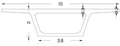
[image:3.595.43.284.187.312.2]The minimum thickness of the deck block as well as that cantilever tips be two hundred millimeter. For prime and base projection having pre-focusing on links, the thickness of such projection might not be but rather one hundred fifty millimeter and breadth of conduit opening. Top Flange thickness = 300 mm > permissible value (safe)
Figure 3.1detail of cross section (units: meter)
2.2.7 Loading on Box Girder:
The different kind of masses, powers and burdens to be contemplated inside the investigation and style of the various parts of the extension are given in IRC 6:2000 (Section II) however the basic powers are pondered to style the model are as per the following: For IRC Class AA loading (IRC 6: 2000, Clause no 207.1, Page no. 10)
2.2.8 Calculation of Ultimate Strength (As per IRC: 18-2000):
i) Due to yield Mult =0.9dbAsFp
ii) Due to crush Mult = 0.176 b db 2fck
2.2.9 Ultimate Moment of Resistance (Analysis Result):
Positive Moment:
Internal B M, MEd = 40251.264kN.m Designed MOR , MRd
MRd=Fc.ac+Fs.as+Ʃ(Fpi.api)=179131.251kN.m (MEd<MRd)
Structure is safe.
Negative Moment:
Internal B M, MEd= 0.00kN.m (From analysis of the model) Designed MOR, MRd
MRd=Fc.ac+Fs.as+Ʃ(Fpi.api)=253578.360 kN.m (MEd<MRd)
Structure is safe.
2.2.10 Shear reinforcement (As per IRC 18: 2000 Clause 14.1.4):
Whenever V, the shear power because of extreme burden is not exactly Vc/2 then no shear support should be given. Least shear fortification might be given when V is more prominent than Vc/2 as connectionsAsv/sv x0.87Fyv/b = 0.4MP
If V> Vc, the shear reinforcement provided.
InternalSF, VEd = 948.194kN Designed SF,
VRd = (Iㆍbw / S)ㆍ√ ((fctd)2 + αlㆍσcpㆍfctd ) ≥ (νmin + k1ㆍσcp)ㆍbwㆍdp
= 5841.628kN VEd < VRd
Maximum BM @ mid section = 10631.1kN.m Maximum Deflection at mid section = 17.06 mm Total concrete quantity = 249.3 m3
Steel quantity = 26.272 MT
2.3 SINGLE CELL PRE-STRESSED CONCRETE BOX GIRDER
2.3.1. Material Properties and Allowable Stress:
2.3.2 Tendon Properties:
Pre-stressing Strand: ϕ15.2 mm (0.6”strand) Yield Strength: fpy = 1.56906 X 10⁶kN/m2 Ultimate Strength: fpu = 1.86326 X 10⁶ kN/m2 Cross Sectional area of each tendon = 0.0037449 m 2 Elastic modulus: Eps = 2 X 10⁸ kN/m 2
Jacking Stress: fpj = 0.7fpu = 1330 N/mm2 Curvature friction factor: μ = 0.3 /rad Wobble friction factor: k = 0.0066 /m
Slip of anchorage: s = 6 mm (At the Beginning and at the End)
2.3.3. Cross Section Specification:
Trapezoidal Shape
Top slab thickness (Tapered) = at the center 300 mm & at corner 200 mm
Bottom Slab thickness = 200 mm External wall thickness = 300 mm Span = 30m
Total width = 10m Road Carriage way width = 7.5m Wearing coat = 80mm
Cross-sectional Area = 4.620 m2 Ixx = 5.199 X 10 m4
Iyy = 2.353 m 4 Izz = 2.652 X 10 m 4 Center: y = 5 m
© 2018, IRJET | Impact Factor value: 6.171 | ISO 9001:2008 Certified Journal | Page 1915 2.3.4 Web thickness: - (As per IRC: 18 – 2000):
Web thickness should not be but rather d/36 and twofold the reasonable spread to the fortification and distance across of the conduit opening where'd‟ is that the general profundity of the container pillar measured from the most elevated of the deck square to the least of the side or two hundred millimetre and the width of channel gaps, whichever is bigger.
Web thickness = 300 mm > permissible value (safe)
2.3.5 Bottom Flange thickness (As per IRC: 18 – 2000):
Base rib thickness might be at least 1/twentieth of the unmistakable web dividing at the intersection with base rib or 200 mm whichever is more. Bottom flange thickness = 300 mm > permissible value (safe)
2.3.6 Top Flange thickness (As per IRC: 18 – 2000):
Deck slab thickness and additionally that at cantilever tips two hundred millimeter. For high and base projection having pre-focusing on links, the thickness of such projection might not be but rather one hundred fifty millimeter and diameter of conduit opening.
[image:4.595.37.283.411.505.2]Top Flange thickness = 300 mm > permissible value (safe)
Figure 2.2 details of Single cell (units: meter)
2.3.7 Loading on Box Girder:
The different sorts of masses, powers and anxieties to be considered inside the examination and style of the fluctuated parts of the extension are given in IRC 6:2000 (Section II) however the basic strengths are considered to style the model are as per the following:
For IRC Class AA loading (IRC 6: 2000, Clause no 207.1, Page no. 10)
2.3.8 Calculation of Ultimate Strength
(As per IRC: 18-2000, Clause no. 13) i) Due to yield
Mult = 0.9dbAsFp ii) Due to crush Mult = 0.176 b db 2fck
2.3.9. Ultimate Moment of Resistance (Analysis Result):
Positive Moment:
internal BM, MEd = 14893.728kN.m
Designed MOR , MRd
MRd=Fc.ac+Fs.as+Ʃ(Fpi.api)=85812.438kN.m (MEd<MRd)
Hence, Structure is safe.
Negative Moment:
Internal BM,MEd = 0.00kN.m Designed MOR, MRd
MRd=Fc.ac+Fs.as+Ʃ(Fpi.api)=103656.221kN.m (MEd<MRd)
Hence, Structure is safe.
2.3.10 Shear reinforcement (As per IRC 18: 2000 Clause 14.1.4):
Whenever V, the shear power because of extreme burden is not exactly Vc/2 then no shear support should be given. Least shear fortification might be given when V is more noteworthy than Vc/2 as connections
Asv/sv x0.87Fyv/b = 0.4MP
If V> Vc, the shear reinforcement provided.
InternalSF, VEd = 600.456kN
positions P V2 V3 T M2 M3
At 12 mt
span KN KN KN KN-m KN-m KN-m
Left exterior Girder
-399.336 97.954 -14.602
-192.1264 42.9895 238.4307 Interior
girder 1 -466.355 211.258 -15.762 -438.3005 19.3051 590.82 Interior
girder 2
-556.239 288.256 10.258 -102.5065 -2.099 837.5798 Interior
girder 3 -508.752 229.341 31.191 260.345 -20.8122 555.6277 Right
exterior Girder
-452.483 160.271 17.427 119.6927 -53.816 178.9724 IRC- Class AA loading
Left exterior
Girder -583.611 395.511 -22.98 -770.15 27.8 1168.77 Interior
girder 1
-681.611 486.511 -31.988
-864.1455 38.5688 1068.8277 Interior
girder 2 -860.842 641.209 22.077 -207.6559 -4.6872 1560.9097 Interior
girder 3 -773.797 631.092 54.997 -371.208 35.961 940.5436 Right
exterior
© 2018, IRJET | Impact Factor value: 6.171 | ISO 9001:2008 Certified Journal | Page 1916 Designed SF,
VRd = (Iㆍbw / S)ㆍ√ ((fctd)2 + αlㆍσcpㆍfctd ) ≥ (νmin + k1ㆍσcp)ㆍbwㆍdp
= 4668.975kN VEd < VRd
Maximum BM @ mid section = 6276.96 kN.m Maximum Deflection at mid section = 7.189 mm Concrete quantity = 138.6 m3
Steel quantity = 18.167 MT Strand quantity = 180.285 m
3. RESULTS & DISCUSSION
The four cells and single cell box beam bridge templates mentioned/formulated in chapter three area unit analyzed in CSi Bridge code and also the results area unit expressed intimately for 2 varieties of loading specifically, AASHTO loading pattern and IRC category AA loading.
[image:5.595.310.558.75.279.2]3.1 Four cell Box girder bridge-AASHTO and IRC loading
[image:5.595.309.560.319.516.2]Figure 3.1 Deformed shape of four cell box girder bridge
Table 3.1 Analysis results for four Cell box girder at 12 mt section under AASHTO and IRC loading
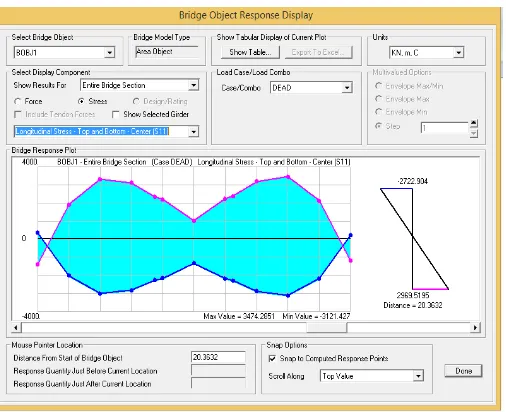
3.2 Bridge response display due to vehicular load(IRC Loading)
3.3Bridge response display due to vehicular load(AASHTO Loading)
[image:5.595.40.220.344.467.2]3.2 Single cell Box girder bridge-AASHTO loading
Figure 3.4 Deformed shape for single cell box girder bridge- AASHTHO loading
At 12
mt P V2 V3 T M2 M3
Under AASHTO loading
m KN KN KN KN-m KN-m KN-m
Left exterior
girder 468.882 - 206.033 64.277 - 54.0368 341.7238 3015.4561 Right
exterior girder
-451.587 365.239 85.134
-835.8185
-350.7367 2818.4975
Under IRC class-AA loading
Left exterior girder Max
-468.882 206.033
-64.277 54.0368 341.7238 3015.4561
Min 468.882 - 206.033 64.277 - 54.0368 341.7238 3015.4561 Right
exterior girder
Max 451.587 - 365.239 85.134 835.8185 - 350.7367 - 2818.4975
© 2018, IRJET | Impact Factor value: 6.171 | ISO 9001:2008 Certified Journal | Page 1917 Figure 3.5 Bridge response display due to vehicular load
[image:6.595.314.556.82.255.2]Figure 3.6Deformed shape of single cell box girder bridge- IRC Class AA loading
[image:6.595.39.292.509.715.2]Figure 5.7 Bridge response display due to dead load
Table 5.1 Analysis results for single Cell box girder at 12 mt section under AASHTO and IRC Loading
3.6 comparission of AASHTO and IRC class-AA
From the higher than table, twisting moment at completion bolster are zero, on account of simply backing condition,however inside the middle bolster it demonstrates the negative BM that is to be
less contrast with positive BM.
The higher than table shows the results of various forces in numerous girders for each IRC and AASHTO codes. The values of axial force in IRC show most at left ext. beam and right ext. girder. once compare to axial forces in IRC and AASHTO. The results of IRC axial forces ar high. equally once scrutiny the shear vertical and shear horizontal results ar additional in IRC codes and AASHTO code results ar less. Moment at vertical axis values is high in IRC code and extremely less in AASHTO code results. the instant at vertical axis values of interior girders ar terribly weak and high within the exterior girders for each codes. Moment at horizontal axis values is incredibly less in AASHTO code and high in IRC code results. the inside girders ar having the less values and exterior girders arhaving the high values in each the codes.
In all forces IRC code results ar additional, as a result of in IRC the codes given for the Vehicle masses isadditional in comparison with AASHTO Codes. thus the pre-cast IGirder bridge is additional stable in IRC code in comparison with AASHTO code values.
© 2018, IRJET | Impact Factor value: 6.171 | ISO 9001:2008 Certified Journal | Page 1918
4. CONCLUSIONS AND RECOMMENDATIONS
The varied span to depth quantitative relation is taken for the analysis of beam bridges, and for all the cases, deflection and stresses ar at intervals the permissible limits.
As the depth of beam decreases, the prestressing force decreases and no. of cables decreases. Attributable to prestressing, additional strength of concrete is used and additionally well governs usefulness.
A comparative study between four cell and single cell pre-stressed concrete beam Cross sections has been done. This study shows that the single cell pre-stressed concrete beam is most fitted and economical crosswise for two lane Indian national road bridges.
It is found that the deflection obtained thanks to varied loading conditions and at service condition is well at intervals permissible limits as per IRC. the utmost vertical deflection is found to occur close to mid-span location of the beam.
For the optimisation of section, different kinds of check out to be performed; those ar applied during thispaper. Results of bending moment and stress for self weight and superimposed weight ar same, however those are totally different for the moving load thought, as a result of IRC codes offers style for the significant loading compared to the AASHTO codes. In load combination, AASHTO codes have taken additional issue of safety than IRC. space of prestressing steel needed for AASHTOis asmaller amountcompared to IRC.
Finally supported this comparative study it’s clear that AASHTO code is additional economical than IRC.
Future scope
1. The same study can be performed by considering other girder types namely Double Cell Box Girder and Triple Cell Box Girder bridges of different radius of curvature, span , length and span length to the radius of curvature ratio.
2. With late progression in material innovation, more study can be focussed on material qualities utilized i.e, different comppsite sections and joint configurations can be make use off to assess the variation in stressess at different locations
3. A further study can be made where an examination of a working with different irregularities like positioning of piers and comparison can also be
given for different bridge types namely, i bridge girder and box girders and simple supported girders and cantilever one.
REFERENCES
1) Angel Lopez and Angel C.Aparicio, “Nonlinear behaviour of curved prestressed box girder bridges”, IABSE PERIODICA 1/1989 Univ. Politecnica de Catalunya, Barcelona, Spain, 2015, pp. 13-28.
2) Mayank Chourasia and Dr. Saleem Akhtar, “Design and Analysis of Prestressed Concrete Box Girder by Finite Element Method”, International Journal of Civil and Structural Engineering Research ISSN 2348-7607 (Online) Vol. 3, Issue 1, pp: (413-421), April 2015 - September 2015
3) Muthanna Abbu, “3D FE modelling of composite box Girder Bridges”, 2nd International Balkans Conference on Challenges of Civil Engineering, BCCCE, 23-25 May 2013, Epoka University, Tirana, Albania
4) P. V. Ramana, “FSM Analysis for Box Girder Bridges”, International Journal of Advanced Electrical and Electronics Engineering (IJAEEE), ISSN (Print) : 2278-8948, Volume-2, Issue-6, 2013
5) Patil Yashavant and Prof. Shinde Sangita, “Comparative analysis of Box Girder Bridge with two different codes”, (IJCIET), ISSN 0976 – 6308(Print), ISSN 0976 – 6316(Online) Volume 4, Issue 3, May June (2013)
6) Kenneth W. Shushkewich (July-1998), Approximate Analysis of Concrete Box Girder Bridges, ASCE, Journal of Bridge Engineering, Vol.114, No.7, Pg. 1644-1657
7) Khaled M. Sennah, John B. Kennedy ( march-2002 ), Littrature Review in Analysis of Box Girder Bridges, ASCE, Journal of Bridge Engineering, Vol 7, No.2, Pg 134-143
8) W. Y. Li, L. G. Tham, Y. K. Cheung, (June1998), Curved Box Girder Bridges, ASCE, Journal of Bridge Engineering, Vol.114, No.7, Pg.1324-1338
9) Ricardo Gaspar, Fernando Reboucas Stucchi, (September-2013), Web Design of Box Girder Concrete Bridges, Engineering Structures 57, Pg. 267-275
© 2018, IRJET | Impact Factor value: 6.171 | ISO 9001:2008 Certified Journal | Page 1919 11) Babu Kurian, Devdas Menon, (July-2007),
Estimation of Collapse Load of Single-cell Concrete Box-Girder Bridges, ASCE, Journal of Bridge Engineering, Vol.12, No.4, Pg. 518- 526
12) Shi-Jun Zhou, (December-2011), Shear Lag Analysis in Prestressed Concrete Box Girders, ASCE, Journal of Bridge Engineering, Vol.16, No.4, Pg. 500-512 159-167
13) Robert K. Dowell, Timothy P. Johnson, (September-2011), Closed-form Shear flow Solution for Box Girder Bridges under Torsion, Engineering Structures 34, Pg. 383-390
14) Imad Eldin Khalafalla, Khaled M. Sennah, (July-2014), Curvature Limitations for Slab-on-I-Girder Bridges, ASCE, Journal of Bridge Engineering, 04014031 Pg.1-14