© 2018, IRJET | Impact Factor value: 6.171 | ISO 9001:2008 Certified Journal | Page 3562
RETROFITTING OF RC CONTINUOUS BEAM WITH GLASS FRP SHEET
Narayan Tiadi
1, B. S. Tyagi
2, Siddharth Jain
31,2
Civil Engineering Department, RGGI Meerut, Uttar Pradesh, India
3Civil Engineering Department, KIET, Ghaziabad, India
---***---Abstract
-To study the behavior of continuous RC beams under static loadingan experimental investigation is carried out . The beams are strengthened with externally bonded glass fibre reinforced polymer (GFRP) sheets. Different schemes of strengthening have been employed. The program consists of fourteen continuous (two-span) beams with overall dimensions equal to (150×200×2300) mm. The beams are grouped into two series labeled S1 and S2 and each series have different percentage of steel reinforcement. One beam from each series (S1 and S2) was not strengthened and was considered as a control beam, whereas all other beams from both the series were strengthened in various patterns with externally bonded GFRP sheets. The present study examines the responses of RC continuous beams, in terms of failure modes, enhancement of load capacity and load deflection analysis. The results indicate that the flexural strength of RC beams can be significantly increased by gluing GFRP sheets to the tension face. In addition, the epoxy bonded sheets improved the cracking behaviour of the beams by delaying the formation of visible cracks and reducing crack widths at higher load levels.Strengthening structures via external bonding of advanced fibre reinforced polymer (FRP) composite is becoming very popular worldwide during the past decade because it provides a more economical and technically superior alternative to the traditional techniques in many situations as it offers high strength, low weight, corrosion resistance, high fatigue resistance, easy and rapid installation and minimal change in structural geometry.
Key Words
: GFRP sheet, RC continuous beam, structural geometry, retrofitting, pre-stressing tendons.1. INTRODUCTION
A structure is designed for a definite time period and it relies on the nature of the structure, its design life is different for structures. A domestic building is designed for 25 years and a public building is designed for 50 years. The infrastructure and bridge industries worldwide, faces deterioration in concrete structures mainly.
Creation of steel jackets that is more competent from strength, stiffness and ductility purpose are other frequent strengthening method. Though, it raises cross-sectional measurements, having raise in self-weight of structures and is labor exhaustive. By switching steel plate with corrosion unaffected and light-weight FRP Composite plates this difficulty can be removed. FRPCs supports to raise strength and ductility without extreme raise in stiffness. Auxiliary, by
applying fibers, such material could be considered to get particular necessities.
By wrapping FRP sheets, retrofitting of concrete constructions gives a more cost-effective and technically better substitute to the outdated methods in many conditions because it deals higher fatigue resilient, higher strength, lower weight, corrosion unaffected, simple and fast fitting and nominal alteration in physical geometry. FRP techniques can also be used in areas with constrained access where outdated methods would be impractical. Nonetheless, as a result of lack of the appropriate abilities on structural behavior of concrete structures, the usage of these substances for retrofitting the prevailing concrete buildings can't attain up to the expectation.
The strength parameters of FRPs jointly create up one of the most essential causes for which civil engineers opt for them in the design of buildings. A fabric's force is ruled by way of its potential to maintain a load without immoderate deformation or failure.
There are 3 wide partitions into which usage of FRP in civil engineering may be categorized: usage for new construction, repair and rehabilitation usage, and architectural usage. By civil engineers, FRPs is being utilized extensively in the design of fresh construction. Buildings such as columns and bridges developed fully out of FRP composites have confirmed great sturdiness, and impressive resilient to consequences of ecological disclosure. Many examples of diverse applications of FRP in new structures are grid reinforcement, reinforcing bars, dowels, and pre-stressing tendons. One of the most usual usage of FRP comprises the repair and rehabilitation of destructive or deteriorating buildings. A couple of businesses across the world are commencing to wrap flawed bridge piers to preserve steel reinforced columns to develop the structural reliability and to avoid buckling of the reinforcement. Architects have also revealed the numerous purposes for which FRP can be utilized. These incorporate buildings equivalent to roofing, siding/cladding, partitions and floor.
© 2018, IRJET | Impact Factor value: 6.171 | ISO 9001:2008 Certified Journal | Page 3563 1.1 BENEFITS OF FRP
Following are the chief benefits of FRP can be enumerated below:
•
Mechanical strength: A supreme material stiffness to density ratio of 3.5 to 5 times that of aluminum or steel can be provided by FRP. FRP is well stronger and stiffer for its weightiness, it is better than other different materials.•
Lighter weight: The FRP is quite lesser condensed and as a consequence lighter than the corresponding amount of metal. And considering that of their mild weight, the transport of FRP substances has nominal ecological influence.•
Longer life: It is highly resilient in fatigue and it has displayed superb longer life over the past 50 years.•
Corrosion unaffected: FRP does nt catch rust. And it has a longer life.•
Chemical unaffected: FRP is nominally responsive, creating it idyllic as a shielding shell for facades where chemical.1.2 FLEXURAL STRENGHTHENING OF BEAMS
Near Surface Mounted (NSM) system, external post tensioning method, steel plate bonding, section enlargement and externally bonded (EB) system are various types of flexural strengthening methods. Between these methods external bonding of advanced fibre-reinforced polymer composite (FRP) method is known worldwide goodly. During the previous decade, their utilization on this subject has been rising because of the famous benefits of FRP composites over different substances. Hence, a first-rate quantity of research, both tentative and hypothetical, has been accompanied on the behaviour of FRP-strethened concrete (RC) constructions. On this regard, the evolving science of utilizing carbon-bonded fibre- reinforced polymers (CFRP) for strengthening of RC beams has got well latest years.
1.3 DRAWBACKS OF FRP
Threat of fire, destruction or accidental destruction, unless the strengthening is secured, is the main concern of outwardly strengthening structures with fibre composite materials. A special trouble for bridges over roads is the threat of soffit reinforcement being hit by means of over-peak vehicles.
An observed drawback of utilizing FRP for strengthening is the reasonably excessive fee of the substances. Though, contrasts should be made on the foundation of the whole strengthening endeavor; in distinct instances the prices can also be lower than that of metal plate bonding. A drawback in the sights of many purchasers would be the deficiency of
expertise of the systems and appropriately certified employees to hold out the task. Subsequently, a giant disadvantage is the shortage of authorized design requisites (Subhashree, 2012).
1.4 OBJECTIVE OF THE STUDY
The target of this work is to hold out the investigation of externally bonded RC steady beams making use of FRP sheet.
In the current work, behavior of RC continuous rectangular beams braced with outwardly bonded GFRP is tentatively premeditated. The beams are assembled into 2 sequence branded S1 and S2. Every sequence have a kind longitudinal and transverse metal reinforcement ratios. All beams have the identical geometrical measurements. These beams are verified up to failure by utilizing relating 2 sorts loading to appraise the improvement of flexural force due to strengthening.
1.5 DESIGN CONCERNS
The enlargement of the developed composite technology is an Engineer's vision for progressive design and its usage. The physiognomies of a composite will also be made and designed to satisfy any preferred standards. Many of the understanding and design info present on composites are within the aerospace functions, but they are blanketed beneath the guise of patented systems and/or military labeled files. In contrast to conventional isotropic substances of metal and concrete, there are no effectively to be had design charts and instructions to aid the structural engineer.
2. METHODOLOGY
TENTATIVE INVESTIGATION
The tentative homework contains of casting of 14 continuous (two-span) rectangular RC beams. All the beams weaken in flexure are casted and verified to failure. The beams were assembled into 2 sequence reflected S1 and S2. Every sequence had diverse longitudinal and transverse steel reinforcement extents for S1 and S2 correspondingly. All beams had the same figural dimensions: 150 mm wider × 200 mm deeper × 2300 mm longer.
CASTING OF SAMPLE
© 2018, IRJET | Impact Factor value: 6.171 | ISO 9001:2008 Certified Journal | Page 3564 Tab.-1: Design Mix proportions
DETAILING OF REINFORCEMENT
[image:3.595.338.540.232.621.2]For the same series of continuous reinforced concrete beams, same arrangement for flexure and shear reinforcement is made.
Fig.-1: Detailing of reinforcements
Fig.-2: Steel frame utilized for casting of beam
STRENGTHENING OF BEAMS
[image:3.595.345.536.238.437.2]On the time of bonding of fiber, the concrete surface is made tough making use of a coarse sand paper texture and then cleaned with an air blower to take away all grime and debris. The fabrics are cut in step with the dimensions and after that the epoxy resin is blended based on brand’s guidelines. The blending is applied in a plastic container (100 parts by weight of Araldite LY 556 to 10 parts by weight of Hardener HY 951).
Fig.-3: Usage of Epoxy and hardener on the beam
Fig.-4: Roller used for the removal of air bubble
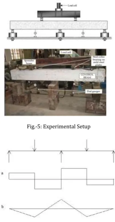
[image:3.595.50.275.267.349.2]Fig.-5: Experimental Setup
Fig.-6: Continuous Beam a. SFD, b. BMD
FABRICATION OF GFRP PLATE
[image:3.595.68.257.386.488.2] [image:3.595.51.272.638.748.2]© 2018, IRJET | Impact Factor value: 6.171 | ISO 9001:2008 Certified Journal | Page 3565 Fig.-7: Samples for tensile testing
4. RESULT AND DISCUSSION
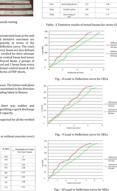
The beams were loaded with a concentrated load at the mid of every span and the achieved tentative outcomes are offered and deliberated consequently in terms of the perceived type of failure & load-deflection curve. The crack forms and the type of failure of every beam are also defined in this chapter. All the beams are verified for their ultimate strengths & it is perceived that the control beam had lesser load carrying capacity than the braced beam. 2 groups of beams i.e. S1 and S2 were inspected and 1 beam from every group was verified as un-strengthened control beam & rest beams were braced with several forms of FRP sheets.
CONTROL BEAM
CB1a and CB2a failed totally in flexure. The failure took place 1st at the tension region & then transmitted in the direction of the compression region & in ending failed in flexure.
BRACED BEAM
Usually, the rupture of FRP sheet was sudden and accompanied by a louder sound specifying a quick discharge of energy & a total damage of load capacity.
The resulting failure types were inspected for all the verified beams:
•
Tensile rupture•
De-bonding failure (with or without concrete cover)•
Flexural failure [image:4.595.175.557.120.741.2]Table; -1 Tentative results of tested beams for series S1
Table; -2 Tentative results of tested beams for series S2
Fig.; -8 Load vs Deflection curve for CB1a
Fig.; -9 Load vs Deflection curve for SB1a
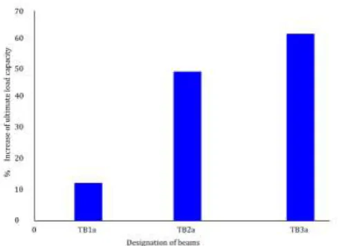
© 2018, IRJET | Impact Factor value: 6.171 | ISO 9001:2008 Certified Journal | Page 3566 Fig.; -11 Ultimate Load (KN) capacity of beam SB2a
Fig.; -12 % Increase Ultimate Load (KN) carrying capacity of braced beam of S2 wrt CB2
4. CONCLUSIONS
The current tentative investigation is been worked out on the flexural behavior of RC rectangular beams braced by GFRP sheets. 14 RC beams weaker in flexure taking distinct set of reinforcement detailing are casted and verified. The beams were assembled into 2 sequence branded S1 & S2. Every sequence had diverse longitudinal & transverse steel reinforcement ratios. From the calculated strength values & test outcomes, these conclusions are observed:
•
As compare to the control beam, the preliminary cracks in the braced beams are made at higher load.•
As compare to the control beam, the ultimate load carrying capacity of all the braced beams is greater.•
Bracing of continuous beam by applying U-wrap of FRP sheet is a fresh and active method of improving the capacity of load carrying.•
To avoid the de-bonding failure, utilization of steel bolt and plate arrangement is a working technique of fastening the FRP sheet.•
Beam SB9a from series S1, which was braced by U-wrap & was anchored by utilizing bolt arrangement & steel plate, revealed the peak ultimate load value of 415 KN. The percentage rise in the load capacity of SB9a was 61.92 %.•
By use of GFRP sheets, flexural failure at the intermediary support section can be prohibited.•
The load carrying capacity of beam SB6a, which was strengthened by 2-layers of U- wrap of length 88 cm. in positive moment region & 2 layers of U-wrap of length 44 cm. over 1st 2-layers, was 415 KN which was closer to the load capacity of beam SB9a. The percentage rise of load carrying capacity was 59.61 %, from which it can be decided that utilizing FRP in the flexure region is pretty active technique to improve the load carrying capacity.•
Beam TB3a from Series S2, which was strengthened by 2-layers of U-wrap in positive moment region & layers of U-wrap in flexure region above 1st 2-layers, was consuming peak ultimate load value of 326 KN, than the other braced beams of similar class. The percentage rise of this beam was 63 % which was utmost amongst all braced beams.•
Beam TB3a from Series S2, which was strengthened by 2-layers of U-wrap in positive moment region & layers of U-wrap in flexure region above 1st 2-layers, was consuming peak ultimate load value of 326 KN, than the other braced beams of similar class. The percentage rise of this beam was 63 % which was utmost amongst all braced beams.REFERENCES
[1] ACI Committee 440, (1996) “Starte-of-the-art report on
fiber reinforced plastic reinforcement for concrete structures”, Report ACI 440R-96, USA: American Concrete Institute.
[2] Grace NF, Wael R, and Sayed AA, “Innovative triaxailly
braided ductile FRP fabric for strengthening structures”, 7th International Symposium on Fiber Reinforce Polymer for Reinforced Concrete Structures, ACI, Kansas City, MO, 2005.
[3] El-Refaie SA, Ashour AF, and Garrity SW, “Sagging and
[image:5.595.39.284.307.485.2]© 2018, IRJET | Impact Factor value: 6.171 | ISO 9001:2008 Certified Journal | Page 3567
[4] El-Refaie SA, Ashour AF, and Garrity SW, “CFRP
strengthened continuous concrete beams”, Proceedings of the ICE - Structures and Buildings, pp. 395 - 404, 2003.
[5] Arduini M, and Nanni A, “Behaviour of pre-cracked R. C.
beams strengthened with carbon FRP sheets”, ASCE Journal of Composites for Construction, vol. 1, No. 2, pp. 63- 70, 1997.
[6] Obaidat YT, Susanne H, Ola D, Ghazi A, Yahia A,
“Retrofitting of reinforced concrete beams using composite laminates”, Construction and Building Materials, vol. 25, pp. 591-597, 2010.
[7] Akbarzadeh H, and Maghsoudi AA, “Experimental and
analytical investigation of reinforced high strength concrete continuous beams strengthened with fiber reinforced polymer”, Materials and Design, vol. 31, pp. 1130-1147, 2010.
[8] Maghsoudi AA, and Bengar H, “Moment redistribution
and ductility of RHSC continuous beams strengthened with CFRP”, Turkish Journal of Engineering and Environmental Sciences, vol. 33, pp. 45-59, 2009.
[9] Ashour AF, El-Refaie SA, and Garrity SW, “Flexural
strengthening of RC continuous beams using CFRP laminates”, Cement and Concrete Composites, vol. 26, pp. 765-775, 2003.
[10] El-Refaie SA, Ashour AF, and Garrity SW, “CFRP
strengthened continuous concrete beams”, Proceedings of the ICE - Structures and Buildings, pp. 395 - 404, 2003.
[11] Engineering Structures, vol. 29(10), pp. 2457–2471,
2007.
[12] Subhashree, Soumya (2012) Strengthening of RC
continuous beams using frp sheet.
[13] Hee SunKim, Yeong SooShin(2011) Flexural behavior of