© 2017, IRJET | Impact Factor value: 5.181 | ISO 9001:2008 Certified Journal
| Page 1744
EXPERIMENTAL ANALYSIS OF DISSIMILAR METAL WELDS OF MILD
STEEL AND STAINLESS STEEL
Brijesh Kumar Maurya
1, Balwant Pratap
2, Avaneesh Kumar
3, Gopal Rana
4 1 2 3 4Students, Department of Mechanical Engineering, IMS Engineering College, Ghaziabad, U.P. India
---***---Abstract -
Dissimilar metals joined or welded together havebeen widely used in all the fields such as automobile industries, nuclear reactors, boilers, petrochemical and chemical industries. The use of two dissimilar metals has increased widely due to light weight and increased mechanical and chemical properties as compared to using the materials separately.
During welding of dissimilar metals various types of defects can be produced like stress corrosion cracking, residual stresses, and unbalanced stress concentration on either side of the weld due to migration of the atoms, thermal stresses and thermal expansion of materials during welding.
In this work Stainless steel 304 is welded to Mild steel 1020 using Gas metal arc welding (MIG).The samples were welded using stainless steel welding electrode: (AWS: E308l-16) under different process parameters. The shielding gas used for this experiment is CO2.Using the tensile test the mechanical
properties of the welded joint were known. The yield strength and the tensile strength of the welded joint, done using stainless steel electrode at the best parameter were noted. Taguchi method is used for getting the optimized value. The results were compared for different joints made by MIG welding processes During the tensile testing the failure of the weld at mild steel base metal gives the correct indication of stronger regions of stainless steel base metal zone.
Further the results shows that increasing the current and voltage increases the strength of welds.
Key Words
:
Tensile strength, dissimilar metal
welding, Metal Inert Gas Welding, MS and SS
1. INTRODUCTION
The stainless steel is one of the most popular materials for structural applications, due to its excellent physical and mechanical properties but it increases the structural cost. The dissimilar metal welds of different steels have very vast requirement for industrial use for conventional structural engineering applications such as civil construction, nuclear reactors, thermal power plants, vessels and heat exchangers
for several industrial applications [1-3].Nowadays the
requirement for production of many engineering and structural components is good joint efficiency, simple process, low fabrication cost, welding reliability and efficient metal joining processes [4]. The various metallurgical changes such as, precipitation of secondary phases,
micro-segregation, presence of porosities, solidification cracking, grain growth in the HAZ and materials loss due to vaporization are the major problems for poor mechanical properties in stainless steel welds [5]. Thus, for structural applications, stainless steels are efficiently utilized by dissimilar welds between carbon steels and stainless steels with economical use of the special properties of steels dependent on the same structure. The various metallurgical changes such as, porosities, solidification cracking, grain growth in HAZ and materials loss by vaporization are the major problems which produces poor mechanical properties in stainless steel welds. Therefore, for structural applications, the stainless steels are utilized efficiently by dissimilar steel welds between stainless and carbon steels with effective and economical utilization of the special properties of each steel dependent in the same structure [6].
2. MIG welding
Metal inert gas arc welding (MIG) also called as gas metal arc welding (GMAW) utilizes a consumable electrode thus the term metal appears in the title. There are other gas shielded arc welding processes utilizing the consumable electrodes, such as flux cored arc welding (FCAW) all these type of welding can be termed under MIG [6].
Though gas metal arc welding (GMAW) can be used to weld all types of metals, it is more suitable for thin sheets. But for welding thicker sheets of metal, the filler metal requirement makes GMAW difficult to use. Consumable electrode is in the
form of a wirereelwhich is fed at a constant rate, through
the feed rollers. The welding torch is connected to the gas supply cylinder which provides the necessary inert gas. The electrode and the work-pieces are connected to the welding power supply. The power supplies are of constant voltage
type only. The current is changed bythe rate of feeding of
the electrode wire. Generally DC arc welding machines are used for GMAW with positive electrode (DCRP). The DCRP increases the metal deposition rate and also provides for a stable arc and smooth electrode metal transfer.
© 2017, IRJET | Impact Factor value: 5.181 | ISO 9001:2008 Certified Journal
| Page 1745
Depending on the current and voltage used for a given electrode, the metal transfer is done in different ways [7-10].
3. Materials and Sample preparation
The materials used and the procedure of specimen preparation is given below.
3.1 Chemical Composition
The chemical compositions of the1020 mild steel and 304 stainless steels are shown in Tables.
Table-1: Chemical Composition of SS 304 [11]
Fe C Si Mn S P Cr Ni
71. 43
0.05 8
0.35 1.32 0.0 7
0.03 2
18. 52
8.28
Table-2: Chemical Composition of Mild Steel 1020 [11]
Fe C Si Mn S P Cr Ni
99.3 1
0.2 0.35 0.4 0.0 5
0.0 4
18. 21
8.06
3.2 Sample Preparation
Specimen of AISI 304 stainless steel and 1020 Mild Steel cylindrical rod with the dimensions given below is prepared [5-6].
Table-3: Specimen dimension
The specimens were turned to above dimensions in a lathe machine and faced to prepare the weld surfaces. The surfaces to be welded were cleaned thoroughly prior to welding. MIG welding process was used for welding steel with mild steel. The AWS: E308l-16 rod of 2 mm diameter filler material was used for all welding process. The specimen prepared is shown in the figure 1 [5] and the
[image:2.595.35.558.40.400.2]specimen geometry is shown in figure 2 [6].
Fig-1: Specimen prepared [5]
Fig-2: Specimen geometry [6]
4. Experimental work
An experiment work is carried out for MIG welding process on dissimilar materials 304Stainless steel and 1020 Mild steel. Good strength can be achieved at high welding rate by proper control on the welding parameter. The experimental work shows the study conducted on tensile strength as output parameter with reference to variable input parameters such as gas pressure, current and voltage [9-10].MIG 300 GN welding Machine is used. The Gas flow rate is 10 L/min.
Table-4: Parameters considered for experiment
These are the required process parameters which are used with their different values for the welding of mild steel and stainless steel test samples.
Overall length 150 mm Distance between shoulders 44 mm
Diameter or width 12 mm Grip section diameter 15 mm Grip section length 53 mm Fillet radius- 5 mm
S.no INPUT PARAMETERS
1 Gas pressure (Psi) 2 Current (Amp) 3 Voltage (V)
S.no CONSTANT PARAMETER
1 Electrode size 2 Shielding Gas
S.no OUTPUT PARAMETER
[image:2.595.309.565.595.697.2]© 2017, IRJET | Impact Factor value: 5.181 | ISO 9001:2008 Certified Journal
| Page 1746
Table-5: Parametric values
The above table shows the values of the different parameters taken for carrying out the experiment.
The Rilon welding machine of MIG Welding is used for this experiment.
[image:3.595.307.558.106.390.2]Fig-3: MIG Welding Machine
Figure shows the Rilon MIG welding machine having power
voltage of 3phase 380V(15%). It has efficiency of 85% and
the type of wire feed is internal feeding. The power factor is 0.85 and the output voltage for MIG is 16.5-29 and for MMA 22.4-32. The rated input current in Ampere is 18.5 for MIG and 20.5 for MMA and the output current adjustment is 50-300 for MIG Welding and 70-50-300 for Manual Metal Arc welding. The overall weight of the entire unit is 60 kg. The welding thickness is generally more than o.8 mm.
[image:3.595.39.279.123.205.2]The UTM testing machine used for tensile testing of specimens
Fig-4: Universal testing machine
Parts of sample prepared
Fig-5: SS and MS weld
Parameter Gas Current Voltage level pressure
[image:3.595.36.285.264.593.2] [image:3.595.308.548.428.694.2]© 2017, IRJET | Impact Factor value: 5.181 | ISO 9001:2008 Certified Journal
| Page 1747
Parts of samples testedFig-6: Tested Welds in UTM
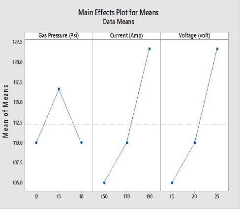
5. Results and Discussions
Table 5 shows the parameters used during welding and results obtained from the tensile test. From the Table 5, it is shown that the maximum value of tensile strength 125 KN is obtained at experiment no 4. While the minimum value of tensile strength 100 KN is obtained at experiment no 1. Figure 7 and figure 8 shows the main effect plots of mean of means and signal to noise ratio graphs of the tensile strength test which are obtained by using Taguchi’s analysis with proper design of experiment.
The result shows that on increasing the current and voltage the tensile strength increasing and more force is required to break the weld. But simultaneously on increasing the gas pressure, current and the voltage the tensile strength decreases as can be seen from the main effect graphs and the result values. The mean of means curve shows the average value of the tensile strength for all the three parameters taken and also the maximum and the minimum values are obtained.
S.NO GAS
PRESSURE (Psi)
CURRENT
(Amp) VOLTAGE (Volt)
TENSILE STRENGTH (KN)
1 12 150 15 100
2 15 170 20 110
3 18 190 25 105
4 12 170 20 125
5 15 190 25 100
6 18 150 15 120
7 12 190 25 105
8 15 150 15 115
[image:4.595.37.278.104.469.2]9 18 170 20 105
Table-5: Results of tensile strength obtained from experiment
Greater the signal to noise ratio more optimized will be the value of the experiment. From the main effect plot for the signal to noise ratio it can be seen that the maximum value of the SN ratio is obtained at maximum current and voltage and the at the average gas pressure. Thus for better value of the response, the optimal values of the parameters should be taken.
[image:4.595.310.564.110.371.2] [image:4.595.311.557.518.731.2]© 2017, IRJET | Impact Factor value: 5.181 | ISO 9001:2008 Certified Journal
| Page 1748
Fig-8: Main effect plot for SN Ratio7. Conclusions
The experimental result shows that the ultimate tensile strength is same for 12 and 18 psi gas pressure and maximum for 15 psi gas pressure. This suggests that on increasing the gas pressure than the required value the strength of weld decreases and is best for average gas pressure. It is shown that the ultimate tensile strength increases with increase of current value from 150 Amp to 190 Amp. From the results we can see the following conclusions:
Firstly as we can see that on keeping gas pressure constant to 12 psi, current to 150 ampere and increasing the voltage to 20 volts the ultimate tensile strength increases. Then on keeping the gas pressure constant and increasing the current and voltage to 170 ampere and 15 -20 volts the ultimate tensile strength increases slightly. But when we increase the gas pressure to 15 psi and kept the current and voltage constant to 150 ampere and 20 volts respectively the ultimate tensile strength decreases.
REFERENCES
[1] Abdul wahab H. Khuder and Esam J. Ebraheam, Study
the factors effecting on welding joint of dissimilar metals‖, Al-Khwarizmi engineering journal, April (2011), Vol 7, No. 1, pp.-76-81.
[2] Wen-chun Jiang and Xue-wei Guan ―A study of the
residual stress and deformation in the welding between
half-pipe jacket and shell Materials and Design, Vol. 43,
2013, PP 213-219.
[3] Man Gyun Na, Jin Weon Kim and Dong Hyuk Lim
―Prediction of Residual Stress for dissimilar metals welding at nuclear plants using Fuzzy Neural Network
Models Nuclear Engineering and Technology, Vol. 39,
2007, PP 337-348.
[4] M.M.A. Khan, L. Romoli, M. Fiaschi, G. Dini and F. Sarri
―Laser beam welding of dissimilar stainless steels in a
fillet joint configuration
Journal of Materials
Processing Technology,
Vol. 212, 2012, PP
856-867.
[5] Yoshiyasu Itoh and Kabushiki Kaisha Toshiba ―Joined
structure of dissimilar metallic materials Patent
Publication Number, EP0923145A2, 1999.
[6] P. Delphin, I. Sattari-Far and B. Brickstad ―Effect of
thermal and weld induced residual stresses on the j-integral and ctod in elastic-plastic fracture analyses
Final Report Vol. SINTAP/SAQ/03, 1998, PP 1-47.
[7] Ajit Hooda, Ashwani Dhingra and Satpal Sharma,
―Optimization of MIG welding process parameter to predict maximum yield strength in AISI 1040, International journal of Mechanical engineering and Robotics research, October (2012), Vol 1, No. 3, pp.-203-213.
[8] T.A. Mai and A.C. Spowage ―Characterization of
dissimilar joints in laser welding of steel-kovar,
copper-steel and copper-aluminium Materials Science and
Engineering, Vol. 374, 2004, PP 224-233.
[9] Paul Colegrove, Chukwugozie Ikeagu, Adam
Thistlethwaite, Stewart Williams, Tamas Nagy, Wojciech Suder, Axel Steuwer and Thilo Pirling ― The welding
process impact on residual stress and distortion Science
and Technology of Welding and Joining, Vol. 14, 2009, PP 717-725.
[10] N.Arunkumar, P. Duraisamy and S. Veeramanikandan
―Evaluation Of Mechanical Properties Of Dissimilar Metal Tube Welded Joints Using Inert Gas Welding
International Journal of Engineering Research and Applications, Vol. 2, Issue 5, 2012, PP 1709-1717.
[11] Wei-Chih Chung, Jiunn-Yuan Huang, Leu-Wen Tsay and
Chun Chen ―Microstructure and Stress Corrosion Cracking Behavior of the Weld Metal in Alloy 52-A508
Dissimilar Welds Materials Transactions, Vol. 52, 2011,
PP 12-19. 50.
BIOGRAPHIES
Brijesh Kumar Maurya is a final year [ME] student of IMSEC, Ghaziabad
Balwant Pratap is a final year [ME] student of IMSEC, Ghaziabad
Avaneesh kumar is a final year [ME] student of IMSEC, Ghaziabad
Gopal Rana is a final year [ME] student of IMSEC, Ghaziabad.
![Fig-1: Specimen prepared [5]](https://thumb-us.123doks.com/thumbv2/123dok_us/8164297.806740/2.595.35.558.40.400/fig-specimen-prepared.webp)