© 2017, IRJET | Impact Factor value: 5.181 | ISO 9001:2008 Certified Journal
| Page 1152
Heat transfer enhancement by using twisted tape insert
H.V.Chavan
1, Prathmesh A. Tapdiya
2, S.S.Birvatkar
2, S.U.Mundhe
2, V.S.Sharma
21
Assistant Professor, Dept. of Mechanical Engineering, FAMT, Ratnagiri, Maharashtra, India
2B.E student, Dept. of Mechanical engineering, FAMT, Ratnagiri, Maharashtra, India
---***---Abstract -
Tubular heat exchanger is a device that enables exchange of heat between two fluids which are at different temperatures and separated by a solid wall occurs in many engineering applications. The one way to enhance the performance of Tubular heat exchanger is to improve tube side heat transfer rate. Twisted tape insert is one of the passive heat transfer enhancement techniques, which are extensively used in various heat transfer applications such as, air conditioning and refrigeration systems, heat recovery processes, food and dairy processes, chemical process plants. A small scale experimental setup was done to enhance the heat transfer rate of tubular heat exchanger. The heat enhancement of Heat Exchanger is done using twisted tape inserts with various twist ratios (TR=3.78, 3.89, 4.22). The effects of two dimensionless parameters namely Nusselt number & Friction factor on the effectiveness of Tubular Heat Exchanger are studied. The turbulent flow was created by inserting the twisted tape inserts into the test pipe creating high rate of turbulence in pipe, which results in increasing heat transfer enhancement and pressure drop. The twisted tape twisting. The length and width of insert was 1000 mm and 45 mm respectively. The outside diameter & inside diameter of test pipe is 50 mm & 48 mm respectively. The length of test section is 1000 mm. The Reynolds number is varied from 5000 to 25000. The results of varying twisted tape inserts with different twisted ratio have been compared with the values for the smooth tube. It showed that the highest heat transfer rate was achieved for the twisted tape with twist ratio 3.78.Key Words: Heat Exchanger, Twisted tape Inserts, Twisted tape inserts with different twisted ratio, Pressure Drop, Reynolds number, Nusselt number.
1. INTRODUCTION
Heat exchanger is a device facilitating heat transfer between two or more fluids. It is extensively used in several industries, such as thermal power plants, chemical processing plants, air conditioning equipment’s generally are operated in turbulent/swirl flow conditions where their performance in terms of energy transfer rate is high, compared with laminar flow by virtue of the high degree of turbulence/swirl flow. Also in turbulent flow, a high intensity of turbulence will enhance the rapid mixing of fluid properties, and the mixing can help to increase the effective area of heat transfer, leading to higher heat transfer rates. Heat exchanger have been classified in many different ways.
The design of heat exchanger is complicated, requiring a consideration of different modes of heat exchanger, pressure drop, sizing, long term performance estimation as well as economic aspect. Tubular heat exchanger are generally built of circular tubes, although elliptical, rectangular or round/flat twisted tubes have also been used in some applications. There is considerable flexibility in design because the core geometry can varied easily by changing the tube diameter, length and arrangement. Tubular exchangers can be designed for high pressures relative to environment and high-pressure difference between the fluids. Tubular exchangers are used primarily for liquid to liquid and liquid to phase change (considering or evaporating) heat transfer applications. The tubular exchangers may be classified as shell and tube, double pipe, and spiral tube exchangers. There are all prime surface exchangers except for exchangers having fins outside/inside tubes. In many engineering applications the high performance thermal systems are needed and thus, various methods to improve heat transfer in the system are need and thus, various methods to improve heat transfer in the system have been developed extensively. The conventional heat exchangers can be generally improved by means of various augmentation techniques with emphasis on several types of surface enhancements. Enhanced surface can create one or more combinations of the following condition that are favourable for the increase in heat transfer rate with an undesirable increase in friction:
a. Interruption of boundary layer development and rising turbulence intensity.
b. Increase in heat transfer area.
c. Generating of swirling and/or secondary flows. Heat transfer augmentation techniques are generally classified into three categories namely: active techniques, passive techniques and compound techniques. Passive heat transfer techniques do not require any direct input of external power. Hence many researchers preferred passive heat transfer enhancement techniques for their simplicity and applicability for many applications. In the present work the experimental investigation of the augmentation of turbulent flow heat transfer in a horizontal tube is done by means of twisted tape with air as the working fluid.
Twisted tape inserts
© 2017, IRJET | Impact Factor value: 5.181 | ISO 9001:2008 Certified Journal
| Page 1153
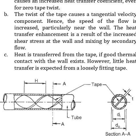
The continuous twisted tape insert shown in Figure 2.7(a)has been investigated for turbulent flow. The insert consists of a thin twisted strip that is slid into the tube. To allow easy insertion of the tape, there is usually a small clearance between the tape width and the tube inside diameter. This clearance results in poor thermal contact between the tape and the tube wall, so the heat transfer from the tape may be quite small. The blockage caused by the finite tape thickness increases the average velocity. Heat transfer enhancement may occur for three reasons:
a. The tape reduces the hydraulic diameter, which causes an increased heat transfer coefficient, even for zero tape twist.
b. The twist of the tape causes a tangential velocity component. Hence, the speed of the flow is increased, particularly near the wall. The heat transfer enhancement is a result of the increased shear stress at the wall and mixing by secondary flow.
[image:2.595.306.562.83.253.2]c. Heat is transferred from the tape, if good thermal contact with the wall exists. However, little heat transfer is expected from a loosely fitting tape.
Fig. 1 Twisted Tape insert
2. EXPERIMENTAL WORK
2.1 Experimental Setup
[image:2.595.47.285.233.471.2]The experimental set up and the various measuring devices are shown in Fig.2 & Fig.3. The apparatus consist of a blower unit fitted with the test pipe. The test section is surrounded by nichrome heater. Four thermocouples are embedded on test section and two thermocouples are placed in the air stream at the entrance and exit of test section to measure air temperatures. Test pipe is connected to the delivery side of the blower along with the orifice to measure flow of air through the pipe. Input to the heater is given through power unit and is measured by meters. It is also noted that only a part of the total heat supplied is utilized in heating the air. A temperature indicator is provided to measure the temperature in the pipe wall in the test section. Air flow is measured with the help of an orifice meter and the water manometer fitted on the board. The valve at the outlet of pipe is used to vary the flow rate of air. At inlet of test section a tapping with valve isprovided to measure pressure drop. The outer surface of the test section was well insulated to minimize heat loss to surrounding.
Fig.2 The schematic diagram of experimentation
Fig. 3 Actual photograph of experimentation
2.2 Procedure
[image:2.595.308.560.298.469.2]© 2017, IRJET | Impact Factor value: 5.181 | ISO 9001:2008 Certified Journal
| Page 1154
2.3 Data Reduction
In the present work the air used as the test fluid is flowed through a uniform heat-flux and insulated tube. At steady state heat taken by the air is assumed to be equal to the convection heat transfer from the test section to air which is expressed as:-
(1)
In which
(2)
(3)
Where
(4)
(5)
The average heat transfer coefficient, h is estimated as follows:
h = / (6)
Where
(7)
Q =
(8)
The Nusselt Number, Nu is estimated as follows:
=
(9)Nu = hd/k (10)
The Reynolds number is given by
Re = (11)
The Friction factor, f is estimated as follows:
=
(12)f = (13)
Where
(14)
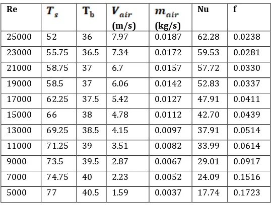
[image:3.595.299.568.143.347.2]Calculation table for Plain tube:-
Table 1 Calculation table for Plain tube
Re
(m/s) (kg/s)
Nu f
25000 52 36 7.97 0.0187 62.28 0.0238
23000 55.75 36.5 7.34 0.0172 59.53 0.0281
21000 58.75 37 6.7 0.0157 57.72 0.0330
19000 58.5 37 6.06 0.0142 52.83 0.0337
17000 62.25 37.5 5.42 0.0127 47.91 0.0411
15000 66 38 4.78 0.0112 42.70 0.0439
13000 69.25 38.5 4.15 0.0097 37.91 0.0514
11000 71.25 39 3.51 0.0082 33.99 0.0614
9000 73.5 39.5 2.87 0.0067 29.01 0.0917
7000 74.75 40 2.23 0.0052 24.09 0.1516
5000 77 40.5 1.59 0.0037 17.74 0.1723
[image:3.595.36.235.175.340.2]Calculation table for Twisted tape inserted inside Plain tube:-
Table 1 for twisted ratio, y = 3.78
Re
(m/s) (kg/s)
Nu f
25000 45.25 32.5 7.97 0.018 94.93 0.1063
23000 47.25 32 7.33 0.017 87.62 0.1256
21000 48.25 33 6.69 0.015 80.00 0.1318
19000 49.5 34 6.06 0.014 71.21 0.138
17000 49.75 33.5 5.42 0.012 70.91 0.1436
15000 51 34 4.78 0.011 68.35 0.1476
13000 51.25 33.5 4.14 0.009 49.64 0.1474
11000 52.75 34 3.50 0.008 45.44 0.1372
9000 54 34.5 2.87 0.007 40.22 0.2050
7000 55.75 35 2.23 0.005 32.66 0.3389
© 2017, IRJET | Impact Factor value: 5.181 | ISO 9001:2008 Certified Journal
| Page 1155
Table 2 for twisted ratio, y = 3.89Re
(m/sec) (kg/sec)
Nu f
25000 48.3 32 7.97 0.0182 89.38 0.0664
23000 49.8 32 7.33 0.0167 75.28 0.0784
21000 52.8 32.5 6.69 0.0153 70.29 0.0753
19000 51.3 32.5 6.06 0.0138 68.68 0.0920
17000 53 33 5.42 0.0123 65.84 0.1149
15000 56 33 4.78 0.0109 50.52 0.1107
13000 55.8 33 4.14 0.0094 44.26 0.1473
11000 56.5 33 3.51 0.008 36.26 0.1372
9000 57.8 33 2.87 0.0065 35.21 0.2050
7000 60.8 33.5 2.23 0.0051 27.36 0.3388
5000 63.3 34 1.59 0.0036 19.86 0.3321
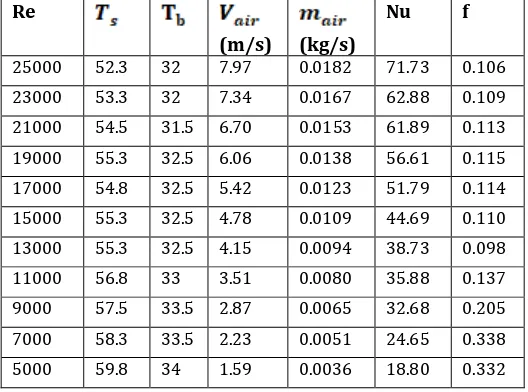
Table 3 for twisted ratio, y = 4.22
Re
(m/s) (kg/s)
Nu f
25000 52.3 32 7.97 0.0182 71.73 0.106
23000 53.3 32 7.34 0.0167 62.88 0.109
21000 54.5 31.5 6.70 0.0153 61.89 0.113
19000 55.3 32.5 6.06 0.0138 56.61 0.115
17000 54.8 32.5 5.42 0.0123 51.79 0.114
15000 55.3 32.5 4.78 0.0109 44.69 0.110
13000 55.3 32.5 4.15 0.0094 38.73 0.098
11000 56.8 33 3.51 0.0080 35.88 0.137
9000 57.5 33.5 2.87 0.0065 32.68 0.205
7000 58.3 33.5 2.23 0.0051 24.65 0.338
5000 59.8 34 1.59 0.0036 18.80 0.332
3. VALIDATION TEST
The Nusselt number and friction factor determined from experimental data are compared with the values obtained from the correlations of Dittus-Boelter for the Nusselt number and Blasius correlation for the friction factor. Comparison between present experimental work and standard correlations for Nusselt number and friction factor turbulent internal flow is presented in Fig.4 and Fig.5 respectively. The results of present work reasonably agree
[image:4.595.30.299.118.392.2]within ± 2 for Nusselt number. From Fig.5 friction factor is observed to reduce with increase in Reynolds number for plain tube.
Fig.4 Comparison of Nusselt number with Reynolds Number
Fig.5 Variation of friction factor with Reynolds number
4. RESULT AND DISCUSSION
[image:4.595.297.557.135.544.2] [image:4.595.30.294.435.631.2]© 2017, IRJET | Impact Factor value: 5.181 | ISO 9001:2008 Certified Journal
| Page 1156
factor decreases with increasing Reynolds number in allcases. Friction factor also observed to be highest for twisted tape of twist ratio 3.78 with. This may be due to highest obstruction caused to air flow.
Fig.6 Comparison of Experimental Nusselt Number with Reynolds Number
Fig.7 Comparison of Experimental Friction Factor with Reynolds Number
5. CONCLUSION
By using twisted tape inserts the highest heat transfer rate was achieved for twist ratio 3.78. In comparison with plain tube all twisted tape inserts would significantly enhance the heat transfer rate. From this experimental study the results can be concluded as follows:-
(For Reynolds number range 5000 to 25000)
1) The Nusselt number for twisted tape insert with twist ratio 3.78, 3.89 and 4.22, increased as twisted ratio decreases.
2) The Friction factor is increased as twisted ratio decreases with twist ratio 3.79, 3.88 & 4.22 respectively.
Nomenclature
f Friction Factor
h Heat Transfer Coefficient Nu Nusselt Number
Re Reynolds Number ΔP Pressure drop Q Heat transfer rate ρ Density of air
Surface Temperature Bulk Temperature Coefficient of discharge Head in meters of water Μ dynamic viscosity of air K Thermal conductivity of the air Pr Prandlt number
A Surface area of tube
ACKNOWLEDGEMENT
This experimental work has been done under the support of Prof. Hemant V. Chavan, Finolex academy of management and technology, Ratnagiri, India.
REFERENCES
[1] A Dewan, P Mahanta, K Sumithra Raju & P Suresh
Kumar, “Review of passive heat transfer augmentation techniques”, Proc. Instn Mech.Engrs.Vol.218 Part A: J Power & Energy, (2004), 509-527.
[2] C. Nithiyesh Kumar, P. Murugesan, “Review on twisted
tapes heat transfer enhancement”, International Journal of Scientific & Engineering Research, Vol 3, (2012).
[3] S.Naga Sarada, A.V.Sita Rama Raju, K.Kalyani Radha,
L.Shyam Sunder, “Enhancement of heat transfer using varying width twisted tape inserts”, International Journal of Engineering, Science & Technology, Vol.2, (2010),107-118.
[4] P. Promvonge, “Thermal augmentation in circular tube
with twisted tape and wire coil turbulators,” Energy Conversion and Management, vol.49, no.11, pp.2949– 2955, 2008.
[5] S. R. Krishna, G. Pathipaka, and P. Sivashanmugam, “Heat
transfer and pressure drop studies in a circular tube fitted with straight full twist,” Experimental Thermal and Fluid Science, vol. 33, no3, pp.431–438, 2009.
[6] Kurhade Anant Sidhappa, Sonal S. Hande, Swarup B.
Patil, Vivekanand R.Maske “Heat transfer enhancement by using twisted tape inserts with circular holes in forced convection”, International journal of innovations in engineering research and technology, volume 3, issue 3, mar.-2016.
[7] Sarang S. Hole, Hanumant B. Narute “A Bird view on