© 2018, IRJET | Impact Factor value: 6.171 | ISO 9001:2008 Certified Journal | Page 3682
Comparative Study on Seismic Behaviour of R.C. Shear Wall at Different
Location in R.C. Building
B.Priyadharshini
1& C.Subramanian
21
M.E Scholar, Department of Civil Engineering, A.C.Govt.College of Engineering and Technology, Karaikudi.
2Assistant Professor, Department of Civil Engineering, A.C.Govt.College of Engineering and Technology, Karaikudi.
---***---Abstract -
Most earthquake-related deaths are caused by the collapse of structures and the construction practices play a tremendous role in the death toll of an earthquake, therefore special attentions are required to evaluate and to improve the seismic performance of multi storied buildings. Shear walls are extensively used for buildings to resist lateral loads induced by earthquake. When shear walls are situated in advantageous positions in the building, they can form an efficient lateral force resisting system. Providing shear walls at adequate locations substantially reduce the displacements due to earthquake. The present work was made in the interest of studying the performance of R.C frame building with and without shear wall under earthquake load and the focus is to identify effective location of shear wall in multi-storey building. A R.C building frame which is regular in plan is considered. Nine different cases of shear wall position for a fifteen storey building has been analysed for seismic zone-III and their seismic performance is analysis by performing Equivalent Static Method, Response spectrum Method, Elastic Time History analysis. The analysis is carried out using ETABS software. The parameters like maximum storey displacement, storey drift ratio and storey shear are considered to locate the effective location of shear wall from the analysis results of RC buildings with different shear wall locations .Keywords: Shear wall, Effective location, Static analysis, Dynamic analysis, Storey drift, ETABS etc.
1. INTRODUCTION
Past earthquakes in our country brought home the harsh reality that earthquakes don’t kill people, unsafe buildings do. About 60% of the land area of our country is susceptible to damaging levels of seismic hazard. We can’t avoid future earthquakes, but preparedness and safe building construction practices can certainly reduce the extent of damage and loss. Earthquake shaking generates inertia forces in the building, which are proportional to the building mass. Since most of the building mass is present at floor levels, earthquake-induced inertia forces primarily develop at the floor levels. These forces travel downwards - through slabs and beams to columns and walls, and then to the foundations from where they are dispersed to the ground. An introduction of shear wall represents a structurally efficient solution to stiffen a building structural system because the main function of a shear wall is to increase the
rigidity for lateral load resistance. Lateral forces caused by wind, earthquake, and uneven settlement loads, in addition to the weight of structure and occupants; create powerful twisting (torsion) forces. These walls generally start at foundation level and are continuous throughout the building height. Their thickness can be as low as 150mm, or as high as 400mm in high rise buildings. Shear walls are like vertically-oriented wide beams that carry earthquake loads downward to the foundation. Shear walls provide large strength and stiffness to buildings in the direction of their orientation, which significantly reduces lateral sway of the building and thereby reduces damage to the structure and its contents.
2. MODELLING
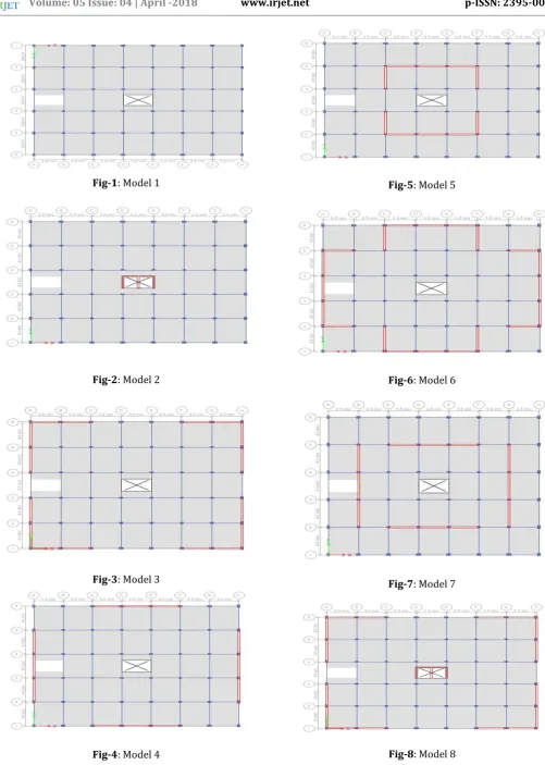
[image:1.595.303.550.561.770.2]RC building of G+14 with 3.3m height for each story, regular in plan is modelled. These buildings were designed in compliance to the Indian Code of Practice for Seismic Resistant Design of Buildings[6]. The buildings are assumed to be fixed at the base. The sections of structural elements are rectangular. Storey heights of buildings are assumed to be constant except the ground storey of height 4.5m. The buildings are modelled using ETABS software. Nine different models were created and studied with different positioning of shear wall in building given in table-1. Models are studied in seismic zone III
.
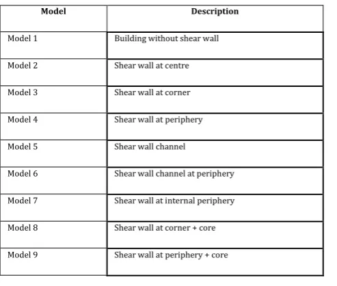
Table -1: Model reference
Model Description
Model 1 Building without shear wall
Model 2 Shear wall at centre
Model 3 Shear wall at corner
Model 4 Shear wall at periphery
Model 5 Shear wall channel
Model 6 Shear wall channel at periphery
Model 7 Shear wall at internal periphery
Model 8 Shear wall at corner + core
© 2018, IRJET | Impact Factor value: 6.171 | ISO 9001:2008 Certified Journal | Page 3683
Fig-1: Model 1
Fig-2: Model 2
[image:2.595.45.547.57.761.2]Fig-3: Model 3
Fig-4: Model 4
Fig-5: Model 5
Fig-6: Model 6
Fig-7: Model 7
© 2018, IRJET | Impact Factor value: 6.171 | ISO 9001:2008 Certified Journal | Page 3684 Fig-9: Model 9
2.1Description of Structure
3.SEISMIC ANALYSIS
Methods used for earthquake analysis are:
1. Static analysis 2. Dynamic analysis
3.1 Static Analysis
It is known as equivalent static force method. In this method, the base shear is calculated from the weight of building. Earthquake forces are calculated in normalized way in this method. This is permitted in most codes of practice for regular, low- to medium-rise buildings. It begins with an estimation of base shear load and its distribution on each story calculated by using formulas given in the code. Tall buildings (over, say, 75 m), where second and higher modes can be important, or buildings with torsional effects, are much less suitable for the method and require more complex methods to be used in these circumstances.
3.2 Dynamic Analysis
Sometimes, for the analysis purpose equivalent static force is not sufficient. Dynamic analysis can be performed by using the following methods.
1. Response Spectrum Method 2. Time History Method
4.RESULTS
The following analysis are carried out as per IS: 1893-2002(Part-I) for fifteen storied building models. For the analysis, Seismic zone-III is considered. According to IS: 1893-2002 (Part-I) Zone Factor, Z=0.16, Importance factor, I=1.00, Response reduction factor, R=5.00, [6] are applied during analysis.
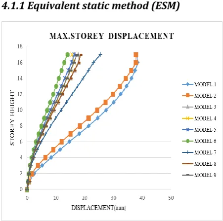
4.1 Maximum Storey Displacement
4.1.1 Equivalent static method (ESM)
Chart-1: Maximum storey displacement-ESM Structure : Frame- R.C.Shear wall
No. of storey : G +14
Storey height : i) Ground storey 4.50 m
ii) Upper storey 3.30 m
Type of building : Public building
Foundation Type : Isolated footing
Thickness of slab : 165mm
Thickness of shear wall
: 230 mm
Beam sizes :0.23x0.35m& 0.23x0.45m
column sizes : 0.3x0.45m & 0.4x0.55 m
Unit weight of concrete : 25 kN/m3
Grade of Concrete and steel
: M40 and Fe500
© 2018, IRJET | Impact Factor value: 6.171 | ISO 9001:2008 Certified Journal | Page 3685
4.1.2 Response spectrum method (RSM)
Chart-2: Maximum storey displacement along X direction-RSM
Chart-3: Maximum storey displacement along Y direction-RSM
4.1.3 Time history method (THM)
Chart-4: Maximum storey displacement along X direction-THM
[image:4.595.36.261.313.484.2]Chart-5: Maximum storey displacement along Y direction-THM
Table -2: Percentage reduction in lateral displacements
Model ESM
(%)
RSM-X (%)
RSM-Y (%)
THM-X (%)
THM-Y (%)
Model 1 0 0 0 0 0
Model 2 1.678 14.619 12.326 3.73 3.31 Model 3 53.293 57.367 64.883 57.19 66.06 Model 4 57.640 56.219 64.275 53.38 63.28 Model 5 59.701 66.276 45.446 65.33 45.01 Model 6 66.447 68.311 72.446 70.11 80.44 Model 7 39.748 54.685 64.428 55.42 61.13 Model 8 53.579 57.721 64.863 60.43 65.37 Model 9 57.677 56.614 64.366 53.64 63.03
4.2 Storey Drift
Story drift can be defined as the lateral displacement of one level relative to the level above or below it.
4.2.1 Equivalent static method
© 2018, IRJET | Impact Factor value: 6.171 | ISO 9001:2008 Certified Journal | Page 3686
4.2.2 Response spectrum method
Chart-7: Maximum storey drift along X direction-RSM
Chart-8: Maximum storey drift along Y direction-RSM
4.2.3 Time history method
Chart-9: Maximum storey drift along X direction-THM
Chart-10: Maximum storey drift along Y direction-THM
4.3 Storey Shear
Base shear is the maximum expected lateral force that will occur due to seismic ground motion at the base of structure and it is equal to the sum of all the storey shear forces at different floors.
Chart-11: Comparison of storey shear for all models
5.CONCLUSION
The behaviour of a R.C. building was analyzed with shear wall at different locations using Equivalent static force method and Response spectrum method and Time history method, conclusion may be drawn from this study.
1. The performance of RC building when subjected to earthquake load is quite poor. So that it is necessary to provide adequate safety to structure against lateral loads.
2. Providing shear walls in the building is the effective method of resisting lateral forces induced by earthquake.
© 2018, IRJET | Impact Factor value: 6.171 | ISO 9001:2008 Certified Journal | Page 3687 4. In equivalent static analysis, it has been found that
Model6 shows lesser displacement as compared to other models in longitudinal direction and gives greater percentage reduction in lateral displacements as 66.447% than that of Model1. 5. In response spectrum analysis Model6 shows lesser
displacement as compared to other models in longitudinal direction and transverse direction and gives maximum percentage reduction of 68.311% and 72.446% (RSM-X and RSM-Y) respectively. In time history analysis it shows 70.110% in THM-X direction and 80.440% in THM-Y direction. 6. The presence of shear wall can affect the seismic
behaviour of frame structure to large extent, and the shear wall increases the strength and stiffness of the structure. It has been found that the shear wall channel at periphery (model 6) shows better location of shear wall since lateral displacement, inter-storey drift and storey shear are less as compared to other models.
7. From the above studies it can be concluded that Equivalent Static Method can be used effectively for symmetric buildings of low-medium height. For higher and unsymmetrical buildings Response Spectrum Method should be used, for important structures. Time History Analysis should be performed as it predicts the structural response more accurately in comparison with other two methods since it incorporates p - ∆ effects and material non linearity which is true in real structures.
8. From all the above analysis, it is observed that in fifteen story building in seismic zone III, constructed building with shear wall channel at periphery (model 6) is effective as compared with other models.
6. REFERENCES
[1] Aainawala M.S and Dr.Pajgade P.S, “Design of
Multistoried R.C.C. Buildings with and without Shear Walls”, International Journal of Engineering Sciences & Research Technology, pp-498-510.
[2] Anjali Kulkarni and VaishnaviDabir, “Study of
variations in dynamic stability of tall structure corresponding to shear wall positions: Case Study”, International Journal of Computational Engineering Research, Vol.6, No. 5, May – 2016.
[3] AshwinkumarB. Karnale and Shinde D.N , “Seismic
Analysis of RCC Building with Shear Wall At Different Locations”, Journal of Civil Engineering and Environmental Technology, Vol. 2, No. 15 ,pp. 65-68, July-September, 2015.
[4] ChandurkarP.andDr.Pajgade P.S, “Seismic Analysis
of RCC Building with and Without Shear Wall”, International Journal of Modern Engineering Research, Vol. 3, No. 3, pp-1805-1810.
[5] Danish M, Zaid M, Shariq M, Masood A and BaqiA,
“Seismic performance of RC buildings with shear
wall”, International conference on trends and challenges in concrete structures, Ghaziabad, December 19-21, 2013.
[6] IS 1893 – 2002, Criteria for Earthquake resistant