Assembly Development
ROM Manual
For the HP 9845
rhO-
HEWLETT
Hewlett-Packard products are warranted against defects in materials and workmanship. For Hewlett-Packard Desktop Computer Division products sold in the U.S.A. and Canada, this warranty applies for ninety (90) days from date of delivery.* Hewlett-Packard will, at its option, repair or replace equipment which proves to be defective during the warranty period. This warranty includes labor, parts, and surface travel costs, if any. Equipment returned to Hewlett-Packard for repair must be shipped freight prepaid. Repairs necessitated by misuse of the equipment, or by hardware, software, or interfacing not provided by Hewlett-Packard are not covered by this warranty.
NO OTHER WARRANTY IS EXPRESSED OR IMPLIED, INCLUDING, BUT NOT LIMITED TO, THE IMPLIED WARRANTIES OF MERCHANTABILITY AND FITNESS FOR A PARTICULAR PURPOSE. HEWLETT-PACKARD SHALL NOT BE LIABLE FOR CONSEQUENTIAL DAMAGES.
Assembly Development ROM
Hewlett-Packard Desktop Computer Division
3404 East Harmony Road, Fort Co!!ins, Colorado 80525
Printing History
Periodically, this manual is updated. Each new edition of this manual incorporates all material updated since the previous edition. Each new or revised page is indicated by a revision date.
The date on the back cover changes only when each new edition is published.
Tabie of Contents
Chapter 1: General Information
Equipment Supplied ... 1-2 Structure of the Manual ... 1-2 Purpose of the ROMs ... 1-3 ROM Installation ... 1-3 Buzzwords ... 1-5 Fundamental Syntax ... 1-7
Chapter 2: Getting Started
Developing Routines for Later Use ... 2-1 Overview ... 2-3 Program Creation ... 2-3 Program Entry ... 2-8 Other Extensions ... 2-10 Modules and Routines ... 2-11 Names ... 2-11 Survey of Modules and Routines ... 2-12 Setting Aside Memory ... 2-13 Retrieving and Storing Modules ... 2-16
Chapter 3: The Processor and the Operating System
Chapter 4: Assembly Language Fundamentals
Program Entry ... 4-1 Assembly Language Source ... 4-3 Actions ... 4-3 Labels ... 4-3 Comments ... 4-5 Syntaxing the Source ... 4-5 Creating Modules ... 4-7 Storage ... 4-8 Modules ... 4-8 Variables ... 4-8 Data Generators ... 4-9 Repeating Instructions ... 4-12 Assembling ... 4-13 Effect of BASIC Environments ... 4-14 Source Listing Control ... 4-14 Page Format ... 4-16 Page Length ... 4-16 End-of-Page Control ... 4-17 Page Headings ... 4-18 Blank Line Generation ... 4-18 Non-Listable Pseudo-Instructions ... 4-19 Conditional Assembly ... 4-19 Control of Indirection ... 4-22 Relocation ... 4-22 Module Reassembly ... 4-23 Symbolic Operations ... 4-24 Predefined Symbols ... 4-24 Defining Your Own ... 4-26 Literals ... 4-27 Evaluation of Literals ... 4-27 Nesting Literals ... 4-28 Nonsensical Uses of Literals ... 4-29 Literal Pools ... 4-30 Expressions ... 4-31 External Symbols and Elements ... 4-33 Other Absolute Elements ... 4-34 Utilities ... 4-36
Chapter 5: Arithemetic
Normalization ... 5-12
Rounding ... 5-12
Floating Point Multiplication ... 5-13
Floating Point Division ... 5-15
The FDV Instruction ... 5-1 7 Thirteen-Digit Dividends ... 5-18
Floating-Point Division Example ... , ... " ... 5-19
Arithmetic Utilities ... 5-21
Utility: ReI_math ... 5-21
Utility: ReI to int ... 5-24
Utility: ReI-to -sho ... 5-25
Utility: Int to reI ... 5-26
Utility: Sho to reI ... 5-27
Chapter 6: Communication Beiween BASiC and Assembly Language
The ICALL Statement ... 6-1
Corresponding Assembly Language Statements ... 6-2
Arguments ... 6-3
"Blind" Parameters ... 6-6
Getting Information on Arguments ... 6-7
Utility: Get_info ... 6-8
Retrieving the Value of an Argument ... 6-12
Utility: Get value ... 6-12
Utility: Get element ... 6-14
Utility: Get bytes ... 6-15
Utility: Get elem bytes ... 6-16
Changing the Value of an Argument ... 6-18
Utility: Put value ... 6-18 Utility: Put-element ... 6-19
Utility: Put-bytes ... 6-20
Utility: Put-elem bytes ... 6-22
Using Common .. ~ .... ~ ... 6-23
Busy Bits ... 6-26
Utility: Busy ... 6-27
Utility: To_system ... 6-28
Chapter 7: 110 Handling
Peripheral-Processor Communication ... 7-1
Interfaces ... 7-2
Registers ... 7-2
Select Codes ... 7-3
Status and Control Registers ... 7-4
Status and Flag Lines ... 7-4
Programmed I I 0 ... 7-6
Interrupt 1/0 ... 7-7 Priorities ... 7-8
Interrupt Service Routines and Linkage ... 7-9
Breaking Interrupt Service Routine Linkage ... 7-9 Access ... 7-10
Utility: Isr_access ... 7-13
Disabling Interrupts ... 7-15
Indirect Addressing in ISRs ... 7-18
Enabling the Interface Card ... 7-19
Interrupt Transfer Example ... 7-20
Direct Memory Access (DMA) ... 7-22
DMA Registers ... 7-22
DMA Transfers ... 7-23
BASIC Branching on Interrupts ... 7-27
ON INT Statement ... 7-27
Signalling ... 7-28
Prioritizing ON INT Branches ... 7-30
Environmental Considerations ... 7-32
Disabling ON INT Branching ... 7-32
Mass Storage Activities ... 7-33
Reading from Mass Storage ... 7-33
Utility: Mm read start ... 7-35
Utility: Mm -read - xfer ... 7 -35
Writing to Mass Storage ... 7-37
Utility: Mm write start ... 7-37
Utility: Mm - write -test ... 7-38
System File Information ... 7-39
Utility: Get file info ... 7-40
Utility: Put-file -info ... 7-41
Communicati0l1 withBASIC Data Files ... 7-42
Interrelation of Record Types ... 7-43
Crossing Record Boundaries ... 7-44
File Marks ... 7-47
Determining Data Types ... 7-48
Printing ... 7-49
Utility: Printer select ... 7-49
Utility: Print String ... 7-50
Utility: Print-no If ... 7-52
The Beep Signal~ .. ~ ... 7-53
Expediting I/O ... 7 -53
Chapter 8: Debugging
Symbolic Debugging ... 8-2
Stepping Through Programs ... 8-3
Individual Instruction Execution ... 8-3
Setting Break Points ... 8-7 Simple Pausing ... 8-7
Transfers ... 8-8
Environments ... 8-9
Data Locations ... 8-11
IBREAK Everywhere ... 8-12
Number of Break Points ... 8-13
Clearing Break Points ... 8-13
Interrogating Processor Bits ... 8-14
Dumps ... 8-14
Value Checking ... 8-17
Functions ... 8-17
DECIMAL ... 8-17
IADR ... 8-19 IMEM ... 8-19 Interrupting Registers and Flags ... 8-20 Patching ... 8-21 Stepping vs. Running ... 8-22
Chapter 9: Errors and Error Processing
Types of Errors ... 9-1 Syntax-Time and Assembly-Time Errors ... 9-2 Run-Time Errors ... 9-2 Utility: Error exit ... 9-3 Run-Time Messages ~ ... 9-5 Assembly-Time Messages ... ' ... 9-8
Chapier iO: Graphics
Introduction ... 10-1 The Graphics Raster ... 10-2 Displaying the Graphics Raster ... 10-2 The Graphics Memory ... 10-3 Graphics Operations ... 10-5 Checking for Graphics Hardware ... 10-5 Overview ... 10-5 Operation: Writing Individual Pixels ... " ... 10-7 Operation: Writing Full Words ... 10-11 Operation: Clearing Full \Nords ... 10-15 Operation: Reading Full Words ... 10-18 Operation: Cursor Operations ... 10-22 Comprehensive Example ... 10-25 Line Drawing ... 10-27
Appendix A: ASCII Character Set
ASCII Character Codes ... A-I
Appendix B: Machine Instructions
Detailed List ... B-1 Condensed Numerical List ... B-12 Alphabetical List ... B-12 Bit Patterns and Timings ... B-13
Appendix C: Pseudo-Instructions ... C-1
Appendix D: Assembly Language BASIC Language Extensions Formal Syntax ... D-1
Appendix E: Predefined Assembler Symbols ... E-1
Appendix F: Utilities ... F-1
Appendix H: I/O Sample Programs
Handshake String Output ... H-l Handshake String Input ... H-3 Interrupt String Output ... H-5 Interrupt String Input ... H-7 DMA String Output ... H-I0 DMA String Input ... H-12 HP-IB Output/Input Drivers ... H-15 Real Time Clock Example ... H-19
Appendix I: Demonstration Cartridge
Using the Tape ... 1-1 Typing Aids ... 1-1
Appendix J: Error Messages
Mainframe Errors ... J-l I/O Device Errors ... J-ll CSTATUS Element 0 Errors ... J-12 Assembly-Time Errors ... J-12 IMAGE Status Errors ... J-13
Appendix K: Maintenance
Maintenance Agreements ... K-l
Appendix L: 9835/9845 Compatibility ... L-l
Chapter
1
General Information
Welcome to the world of assembly language programming on the System 451 •
It is the design of the Assembly Execution and Development Read Only Memory (ROM) and the Assembly Execution ROM to help extend the capabilities of your 9845 by giving you greater control and speed through the use of machine instructions, pseudo-instructions, and exten-sions to the BASIC language.
The assembly language system is provided to you as one of two ROMs which plug into the right ROM drawer of your System 45. The two ROMs are:
• The Assembly Execution and Development ROM - used to write and debug assembly language programs on the System 45, and has the complete capability of the Assembly Execution ROM .
• The Assembly Execution ROM - provides the capability to load, run, and store assem-bled routines and modules. Information about this ROM can be found in the Assembly Execution ROM manual.
When installed, the Assembly Execution and Development ROM reserves some read/write memory which cannot be accessed for storage of programs or data. {The Assembly Execution ROM also reserves memory.} The following table describes the actual read/write memory used {in 8-bit bytes} under various configurations:
Execution ROM Only Execution and Development ROM
1/0 ROM Present 1/0 ROM Not Present 1/0 ROM Present 1/0 ROM Not Present
Power on After
first pre-run
270
708
334
772
590 654
1028 1092
It is assumed throughout this manual that you are familiar with the basic operation and lan-guage of the 9845. It is also assumed that you are reasonably well-acquainted with at least one other assembly language.
Equipment Supplied
The following items are supplied with the Assembly Execution and Development ROM
-Item
Assembly Development ROM Manual Assembly Execution ROM Manual Assembly Language Quick Reference BASIC Language Interfacing Concepts Demonstration Cartridge
Error Label
Part Number
09845-91083 09845-91082 09845-91080 09835-90600 11141-10155 7120-8771
Structure of the Manual
It is the intent of this manual that you should be able to find between its covers everything you need to know to use the assembly language effectively. However, since assembly language programming is a complex topic, the manual relies a great deal on your past experience. Most of the information is in succinct presentations of a particular topic; it is not the intent to "teach" assembly language programming to someone not familiar with the topic.
The major topics covered are: assembly language program creation, the processor and relevant operating system constructs, assembly language fundamentals, BCD and integer arithmetic, communications with BASIC, I/O handling, debugging tools, errors and error processing, and graphics. Each topic (chapter), has a summary at the beginning detailing the information to be presented therein.
The manual is organized so that each topic can be covered completely within a given chapter. This approach was chosen over the strict syntactical or seman tical treatment of the individual statements and instructions. As a consequence, you may find this difficult to use as a "quick reference" for syntax and meaning of the indivldual commands.
To meet your needs for "quick reference" material, an Assembly Language Quick Reference Manual (HP part number 09845-91080) is provided. In addition, you will find much of the information in this manual condensed and tabulated in the various appendices of this manual.
Purpose of the ROMs
The Assembly Execution and Development ROM is used to write and debug assembly language programs on the System 45, and also has the complete capability of the Assembjy Execution ROM. The Assembly Execution ROM provides the capability to load, run, and store assembled routines and modules.
The Assembly Execution ROM is used independently of the Assembly Execution and De-velopment ROM. Because of the overhead required by the debugging features of the Assembly Execution and Development ROM, programs run slightly more rapidly if the Assembly Execu-tion ROM is used rather than the Assembly ExecuExecu-tion and Development ROM.
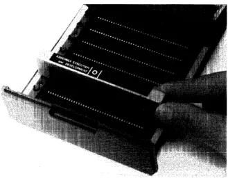
ROM Installation
Before assembly language programming can proceed, the ROMs must be in place. The installa-tion is a simple process.
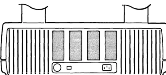
There are two ROM drawers for the computer: one on the right side of the machine one on the left. The ROM is installed in the right ROM drawer, using these steps:
• Pull the right ROM drawer out.
• Squeeze the sides of the plastic cover and lift to gain access to the drawer connectors.
• Position the ROM over one of the connectors denoted by a
0
or [] marking.Assembly Language System ROM
After inserting the ROM, close the drawer until it is flush with the outside cover of the machine.
[image:14.613.129.458.445.701.2]With this done, you are now ready to begin writing assembly language programs.
Buzzwords
During the course of the discussions in this manual, words and phrases are used which are in common circulation among those who are familiar with assembly languages. While the mean-ings of most are either well-known, or are deducible from the context, there are a few which may be unfamiliar, or unique to the 9845 assembly language, or are variable from one assembly language to the next and thus need to be defined for this one. They are
-assembled location - a reference to a location in memory which may be specified in one of the following forms
-{symbol} [ ~ {numeric expression} ] {expression} [ 'l {numeric expression} ]
where:
{symbol} is an assembly location. It may be a label for a particular machine instruction (in which case the address of the associated instruction is used), or an assembler-defined symbol (in which case the associated absolute address is used), or a symbol defined by an EQU instruction (described in the "Symboiic Operations" section of Chapter 4).
{expression} may be a numeric expression or a string expression. If numeric, a decimaj calculation is performed and the result is interpreted as an octal value; if the result is not an octal representation of an integer, an error results. If a string expression is used, the string must be interpretable as either an octal integer constant or a known assembly symbol (see {symbol} above).
{numeric expression} serves as a decimal offset from the given label or constant.
busy bits - each variable located in the BASIC value or common areas has associated with it two bits: a "read" busy bit, and a "write" busy bit. When a "read" busy bit is set, attempts should not be made to perform a function on that variable. A read operation may be performed on a "write-busy" variable. When the busy bit is cleared, the function may be performed on the variable.
byte - a group of 8 binary digits (bits).
interrupt service routine (lSR) - an assembly language routine intended to perform a certain action, or set of actions, when the computer receives a request from an external device. An "active" ISR is one which is currently enabled for a given device.
mass storage unit specifier (msus) - a single word corresponding to the BASIC lan-guage mass storage unit specifier as described in either the 9845 Operating and Pro-gramming Manual or the Mass Storage Techniques Manual. An msus has one of the following structures
-Unit HPIB Device Select
Number2 Address Type1 Code
I I I I I I I I I I I I
I I I I I I I I I I I I
15 14 13 12 11 10 9 8 7 6 5 4 3 2 OBit
or
Unit Device Select
Number Type1 Code
I I I I I I I I I I I I
I I I I I I I I I I I I
15 14 13 12 11 10 9 8 7 6 5 4 3 2 OBit
for the 9885MS Flexible Disk Drive
An msus can designate the current default as its mass storage device (meaning it will use the device indicated by the last MASS STORAGE IS statement executed). This is desig-nated by having the msus be all ones (Le., equal to - 1).
object module - a section of assembled code stored in the particular region of memory set aside for it. Though the source module for the object code may no longer be resident in memory, when created, the module was delimited by certain pseudo-instructions (NAM and END) and is referenced by the name given to it by the NAM pseudo-instruction.
octal expression - a numeric expression which, when displayed or printed, appears as an octal (base-8) number. Within arithmetic operations, it has a decimal value (base-l0). Thus, the value 178 will appear as 17 (representing the value 1510), but if arithmetic was performed on it, it would act as if it were 1710. All octal expressions are necessarily integers in the range of 0 to 1777778.
1 The device type is the ASCII code for the type minus 1008.
pixel - picture element - the smallest unit of resolution on the CRT.
source module - a section of assembly language source code beginning with a NAM
pseudo-instruction and ending with the END pseudo-instruction.
word - two bytes; a group of 16 binary digits (bits).
B - octal radix specifier. For example 1777778 is 177777 octal. If the trailing "8" is not present, the assembler assumes decimal.
*-
shorthand for current location. For example,is equivalent to
-Fundamental Syntax
The syntax conventions used in this manual are those used in the Operating and Programming Manual for the 9845.
ck::t ffa tr-· i >:: All syntax items displayed in dot matrix form should be pro-grammed as shown.
[] Items contained in brackets are optional items.
Ellipses mean that the previous item may be repeated indefinitely.
In addition, the following convention is employed throughout the Assembly Language series of
Chapter
2
Getting Started
Summary: This chapter contains a general discussion of the assembly language sys-tem. A format for the creation of an assembly language program is presented. Topics such as modules, routines, and memory allocation are discussed, along with methods of using them effectively. Also discussed is the storage and retrieval of modules on mass
...
_
... ,... ...;:>LVLa~",.
The thing to remember about the ass~mbly language system is that it has been thoroughly integrated into the operating system of the System 45. Once the ROMs have been installed, you are able immediately to begin programming in assembly language. In addition, you have the capability to load and store your programs on mass storage, to assemble them separately or leave them in source form, to execute them from BASIC and pass BASIC variables to them, and to debug them, including a full pausing and stepping capability.
Developing Routines for Later Use
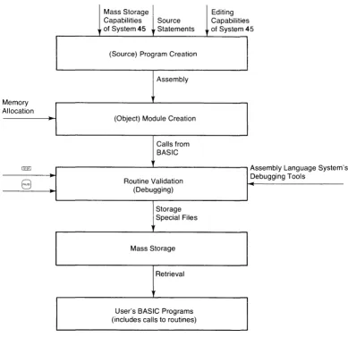
Most assembly language programs are written with the intent that they will be used many times, not just at the time they are written. It is for just such program development that the full capabilities of the assembly language system come into play. The development comes in several stages. Each stage has its unique requirements and the tools to meet those require-ments.
The first stage is creation of the source program. This is achieved by the use of the editing capabilities of the System 45. Additionally, the mass storage capabilities of the computer can be used.
The second stage is the creation of the object (or machine) code. This requires not only an assembly of the source, but the ability to allocate special locations in memory to hold the newly created object code.
The fourth stage is to store away the debugged object code so that it may be used at a later time. A special mass storage statement is provided by the assembly language system. This statement stores object code into a special assembly file.
Finally, the end-user of the routines must be able to retrieve the object code from mass storage as it is needed. He also must be able to access the routines from BASIC programs. Both these needs are met with the Execution ROM, so the capabilities are not only provided, but they are provided independently of the program development capabilities located in the Assembly Execution and Development ROM.
Each of the topics involved in these stages is discussed at length in this manual.
Figure 2 presents a graphical presentation of this overview.
Mass Storage Editing Capabilities Source Capabilities of System 45 .. Statements of System 45
(Source) Program Creation
Assembly
Memory Allocation
(Object) Module Creation
Calls from BASIC
@ill Assembly Language System' s
8
Routine Validation (Debugging) Debugging ToolsStorage Special Files
Mass Storage
Retrieval
User's BASIC Programs (includes calls to routines)
[image:20.613.100.489.326.703.2]Overview
At this point, there are three fundamental structures to be explained: programs, modules, and routines.
A program is the set of source statements from which the object (or machine) code is gener-ated. The assembly source statements are extensions to the BASIC language which is used in the System 45. The statements themselves are stored in the machine as part of the BASIC program in which they reside. At some point, you must take the assembly source statements and assemble them into object code, in order for them to be run. The object code is stored in a specified location in the machine.
A module is a subset of the object code. It is a means of separating and identifying parts of the code so that those parts may be used individually (as in mass storage operations). There may be any number of modules present at anyone time, limited only by the amount of memory allocated for object code.
A routine is a "callable" section of a module. It is analogous to the subprogram in BASIC. It has a named entry point, possibiy a parameter iist, and a return. A moduie may contain any number of routines, again limited only by the amount of memory allocated to hold the object code.
In short, the usefulness of each structure is as follows
-• Programs contain assembly language source code.
• Modules contain object code to be loaded from or stored on mass storage.
• Routines are executable sections of object code.
Program Creation
The first matter which is likely to concern you about the assembly language system is how to create an assembly language program.
In general, the process of creating an assembly language subprogram consists of the following steps
-1. Enter and store the source code (program).
2. Create an area in memory which will ultimately contain the object code.
3. Assemble the source code into object code, storing the latter into the area of memory set aside for it.
Each of these steps will be discussed at length in the pages of this manual, along with a number of not-so-incidental side-topics (such as "debugging" techniques). The purpose of this short section is to give you an impression of the general procedure through which an assembly language subprogram is created.
As an example to use to demonstrate the process, suppose the following task has been assigned to
you-Requirement: Write an assembly language subprogram which takes two integer values and multiplies them together as integers. If the result overflows the range of an integer (- 32 768 to
+
32 767), then the subprogram should return the same error as the system would (Le., error number 20).With this task in hand, suppose that you have completed a programming analysis that suggests that the following assembly language source code would fulfill the subprogram's functions _ 1
5~] I ~:;iJL~F::C:E I (!~)jJt 1 :
60 ISOURCE In~ut2:
7~a I ::;Ci~J F:C:E C!i) t. F)t~t :
120 I :::OURCE
130 I ':;QURCE
240 ISOURCE
:::,::;.-:-, I ::;OURC::
:~~'h.-:-1 I ':;')JF.:CE
~:::?0 ISUURCE
HAM Multiplication! Beginning of module
T=.l-:
1 ,vi!
LIlA =In'l:.e';iEr:=;.+l
LI~t: = I t-lr)~-~ t 2
.J~=; 1-; C; et :.).::t. 1
I,)E-LIlA =20
.Y::;r'l Er"'f"'(/' e::<'i t
::::TA Ir·itei;!E:,,,:;:.
LIlA = I n1:. eger"':=;'
LDB =Outp;..41:.
! I~jicates entry point follows
I r-j:] i (.3. t E-:=:- ii i r-lt E"l;lE'f' ~):it-·.::trfJE"t ~·r-·=· ·:i.r-·e
~):1=.:=.E·ij i r-~ t~·~E· c!f-·:jE't-· ~;Ii !)E-i-! t::: .. 1 rJ-EE';.E'
:::. t.3, t E rflE-(!~.:'::. .:ir-pj .::t.t-·E- 1;1 i !· • .!!::t-I t-~::t.r~·~E·:::· ~ Actt~::t.l !=-ntt-·~) ~)C:if-It <r-~:iff~E': t'l!_~lti~)l~);
r"'Out i ne be';! in:=;. b::..I fet. chi n.; ·:':tc t. i..B 1
' .. '.:':t]; .. H:·
o·r
the input p:':tt .. ·.:iflletef"·::;·from BASIC and st.oring them where the routine can use them
arithmetic accumulator and
! A check for overflow is performed in the B register ~0en it sh~uld be 0
and if it isn~t~ Error 20 is selected and the routine is aborted
If everything is (~, then result st.ored
T~-~:::' ~)t~·::::jt~::::t. 1:::. t.hEr-i r-·Etl.Ar-·i-tE·.j t ( ) tt-~E'
C:iJt t=ltJt !·).3.r-· i -3.L! 1 ~.:. i ~-~ BA~:; I C: 1 i:=-t E'ij
We're finished, so return to BASIC END Multiplication! End of module
Now that the routine has been developed, it is necessary to get it into the memory of the machine as a program. This is done by preceding each and every assembly language statement with the keyword ISOURCE and entering it as a program line. The process of entering (with the keyword included) is the same as with any other BASIC statement - so you can use EDIT or AUTO and the
8
key in the same way you normally enter any BASIC statement. (This process is fully described in the "Program Entry" section of this chapter.)The final result of entering the routine would look something like
-NAM Multipl ication
I r-1t)t4 t 1 : I t-~f=;i) r~ 2 :
Cit~t f)~.At : 1r"41"
80 ISOURCE MultlP!Y: LDA =Integers
LI):B = I (~r)t~i:.l
.J::; rr1 :.).3. 1 ~_~E'
LI111 =-I t-lt ==':J~:='r-':::'+ 1
~:; TA I f-~t E-j~E'
r-':=-LIlA =:If-lte~;]E'r-'="
:1::-r=:.c. ~
END Multiplication
Beginning of module
=.}.3.1 ~_~==', F'trt. :.}.:i. 1 t~E- ~ iJt. i 1 .; + .; ...
-::;t.c;f-·.3.!;iE· .3.r-E"·::t f"c:t-· i (1t.E"i;1E"r--:=. Cr-·E·.~tE·:j
Indicates entry point follows
Ir-j:ji C.:itE-:::. :: i f-;t~':;jZ::'r-' f:8.r--.3.f{;E-t:::"r-·:::. -3..t-·E" r):i.:::·:;·E-"j 1t-l tt-~E' c:r-'C~E'r-' :;i ;·}E·f-~ c::: .. : t.t-p::-:::.e
:::-t-3.1:-effient:::- -3.nd -3.r--",,- gi '---'en
n3.mE-:::-Actt-i.3..1 E·t-ltt-·~~) r;c:it-~~. (r-i-3.UlE": tI1t~ltiF)1:);
~rom BASIC and storing them where the routine can use them
arithmetic accumulator and
H C }Hi~·C k ·fC=f-· ::::~:.)E·(·f-l C:~.:) i:=. f)E·t--F·c,t-·rnE·tj
by checking the result for anything in the B register wh""n it should be 0 and if it isn/t. Errc~ 20 is selected
If everything is OK, thEn result stored The r~Gj~:t is thEn returned to the
c;t~t~::t~t :.).3.(·i.3.Cl1e i~-; E~A~=;IC: 1 istE";j
among the argwBents
This source code demonstrates the three critical items in assembly subprograms. First, a routine has to be part of a module; modules are delimited with the NAM and END pseudo-instructions (see lines 10 and 270 in the source). Second, a routine has to have an entry point; this consists of a SUB pseudo-instruction (see line 40), any parameters (see lines 50 through 70), and a name (the label used on the first machine instruction following the SUB, see line 80). Finally, a routine must be able to return to the BASIC program which called it; this is accomplished with the RET 1 instruction (see line 260).
The next three steps in program creation are each satisfied with BASIC-executable statements.
Creation of a storage area for the object code for the program (which can be estimated at less
than 40 words; there is essentially one word of object code per line of source) is accomplished
by programming the statement
-(The ICOM statement is fully discussed in the "Setting Aside Memory" section of this chapter.)
This can be followed in the same program by an instruction to assemble the source code into
object code
-290 IASSEMBLE Multiplication
(The IASSEMBLE statement is fully discussed in Chapter 4.)
If the assembly is successful (and it will be in this example), then the routine can be called and
used as desired. A typical call looks like
-600 ICALL !'iul tip 1 ',..' (I ndE-::·::, Ii i iflE-n:::· i en, ::::ub:::·c r i pt ::.
6 1 ~3 Rt-·t-·.:i.~:--' (::; t~ti :::·c t-· i r)1:. ::. = \l:~ 1 '-~
E:-(The ICALL statement is fully discussed in Chapter 6.)
Thus, the final result could easily be
-':::CiUF.:U:::
:::UUr-:\A:.
'X:1 ::::OU~:CE
1 D0 ::::OUPCE
i E1 ::::OUF-:CE
1 :3~~1 ~:;CifJF?C:E
140 SOUF.:CE
19>:) '::OUPCE
200 ::::CUF.:CE
210 ::::OUPCE
NAM Multipl ication ! Beginning ot· module EXT Error E~it,Get value,Put value I Utilities
Integers: BSS_
npvt 1: EH i)tput ItH
ultip y: LDA =Integers
LIlA =IntegET:::.+l LDB =Input2
LIH4 I r-(t:.
e=;ier-':::-LDB Int'::·';!'::T:::.+l
f'1P\'
::::BP ++2
t...DA =2D
Indicates Efitry point follews
~):i:::.:::.E·:j i r-~ t t-ie (:(':jE"r-' :;1i !·}E-r-j c=:) t t-~t:':=-e
s~atements and are givEfi names
A::::t[_~3.j E:·~-lt(·~/ ~)c:it-~t ((?-3.rf~E-: ~'1i_.J1 t i ~::1 ~);
routine begins by fetching actual
l.).::t.l t~e c:f t~-iE' i f-~~)t~t t):ir·.:if{i~:·tE·r-·:::,
from BASIC and storing them 41ere the reutine can use them
arithmetic accumulator and finally multipl ies them
A ch~ck for nuerflow is performed by checking the result for anything
in the B register 01~n it shG~ld be n
and i f it isn~t~ Errc~ 20 is ~~lected
among the argumEfits
.--.:.. -
-; :_.::!, :,-, ,_:j":
It isn't necessary that a program be assembled in every BASIC program which uses it. Object code can be stored on mass storage with a statement like
--.::=;:.::-':
So if the example were instead made to read
-T ~'~T
Ir-H
LDA
=lnte,]er--::;-L-1JH T '-it
e';1e'--:::-LIlE I nt e':;it'T:::+l
=Cl~)t ~)~_~t
F: ~_~ t. =.}.3. 1 ;_~
E-Eeginning o~ module
I ~-~ci i ~=.:i. t e.:: -= :--. :.- :'-. I f)'': - - - ... _. .
-1. (;::1 1 C·:i t. :::':::. ;: i r-;t e;~:::'(' ~:;:J.t-·.3.r(l~.:·t ~:'r-'::: . . 3.[-,=:;"
passed in the order ']iven by these :::- t-:i t ==-f{;:::'(~ t:::· .:ir-i;J .3. [-'E:' =;i i =.)t:"r-i f-l·3.f~·{:::':=.
! R::tti.3.1 E-(ltr--:) (':'--l- ... -~.::.- -: :~t~ltiF)l;);
r0~tine begins bv fetching actual
=.).:i. 1 ;_~ E' :_: ; t. r-~ ~~:' .~ (§ ~:;l) t f)3. [-',3. f{l:::'t t:' r-':::·
EASIC ~~: :::~:~-~; -~-
the routine can use them
: ;,.-_.- -.:..
:;::::: :: :.- ; '_:'::i:.J:::.
arithmetic accumulator and
__ check fc~ overflc~
bv checking the resu~t for anvthin in the E register when it Sh0~ld b
and the routine is abc~ted
,-.
""i
It- everythlng is OK, then result stored The product is then retlrnsj to the
~ "! .= T :.:::. :-i
among the arguments
the object code is consequently stored into the file "MUL T".
Later programs can retrieve the object code for use, such as in the following program
-10 INTEGER Dimension,Ind~~,Subscrjpt
600 IeAll Multiply(I0jex,DimEfision,Subscript)
6 i0 Ar--r-.3.::_.;(':;ub:::.cr-· i pt )=\.'-3.1 ue
(Both ISTORE and ILOAD are discussed in the "Retrieving and Storing Modules" section of this chapter.)
Program Entry
The assembly language source statement is an extension to the BASIC language used in the System 45. This means that each assembly language statement is entered using a "keyword" - in this case ISOURCE - as a message to the operating system that the line is an assembly language statement.
By looking at an example, you can see what is meant
-10 LET A=i0
30 PPIt-H A, B
40 I ::;CURCE t-4 H 1'1 E::<.3.mp 1 e
50 ISOURCE NCP
60 ISOUPCE am E::·::.::t.ilIP 1 e
7(1 am
Lines 10, 20, 30, and 70, are all recognizable as BASIC statements. The keywords they use - LET, PRINT, and END - direct that certain actions take place. Lines 40, 50, and 60, are all assembly language statements; this was indicated by the ISOURCE keyword used in these lines.
Also, assembly lines do not have to be in any special place in the BASIC program. The previous example could be rearranged as follows
-40 ISOURCE NOP
Thus, you are free to enter your assembly statements anywhere in your BASIC program. But, you may ask, what is the effect of spreading them out like this? The answer is, simply, none. When the time comes to use them, assembly statements and BASIC statements are separated by the operating system and treated differently.
When the BASIC program is run, only the BASIC statements are executed. The ISOURCE statements are ignored, and, as you will be shown in Chapter 4, when the assembly language lines are assembled, the BASIC statements are ignored. A way to consider it is that there are two programs in one - BASIC's and the assembler's. So you can envision the example above as being this
way-BASIC ASSEMBLER
L .. t.:. ~
~
source~
~'---JrV
:".-'-.. --.: ;:-.. --.,""i :"':! \ . .if"'::i .... t::.
You should note, then, that ISOURCE statements are not "executable" in the usual BASIC sense. Their location in the program does not indicate the place where they will be executed. Assembly instructions are not executed until a routine is "called"; this is discussed in detail in Chapter 4.
Now that it has been said that the two types of statements can be thoroughly intermixed, it should also be said that the practice is not recommended. As a good programming
practice-i.e., for readability and to preserve the self-documenting features of BASIC - it is recom-mended that assembly statements be collected together and placed in one spot in the program.
Other Extensions
In addition to the ISOURCE statement, there are a number of other BASIC language exten-sions provided by the assembly languge system. Unlike the ISOURCE statement, they are
"executable", and their appearances are part of the BASIC lines (as distinguished from the assembler's). Where they appear is where the action associated with them is taken. This is identical to the way the other BASIC statements perform. The statements involved are
-IASSEMBLE IBREAK ICALL ICHANGE ICOM IDELETE IDUMP ILOAD INORMAL IPAUSE OFF IPAUSE ON ISTORE OFF INT ONINT
Also provided are four numeric functions
-DECIMAL IADR 1M EM OCTAL
The functions can be used wherever numeric functions in general may be used.
Modules and Routines
There are three basic activities associated with using assembled modules and routines. First, there is the need to retrieve them from wherever they may be stored (including providing a place for them to be kept while they are resident in the memory of the machine). Second, there is the actual execution of the routines. And third, there is the occasional requirement to store, or re-store a module on mass storage (including, perhaps, the need to free the space in memory it previously occupied).
Names
Routines, modules, and files all have names. The names given them mayor may not bear some significance to one another; that depends upon you and the way that you name things.
Conventions for the naming of files and methods of general file manipulation can be found in the Operating and Programming Manual and in the Mass Storage Techniques Manual. The conventions are not any different than for files in general.
Names for modules are assigned with the creation of the source. In the assembly language source code, you have a NAM pseudo-instruction. This serves two purposes - to designate the beginning of the module and to assign the module a name. All of the assembly source state-ments which follow the NAM are in that module until an END pseudo-instruction is encoun-tered. Thus, recalling the previous
example-20 ISOU~~E NAM ~.ampl_
All of the ISOURCE statements between lines 20 and 60 (in this case, just the one) form the module called "Example". The formal syntaxes of these pseudoinstructions are
-:...::..:..:
{module name} {module name}
The {module name} in the END statement must correspond to the {module name} of the NAM statement or an assembly error ("EN") results.
You may have any number of modules in your source code. Each module begins with a NAM and ends with an END pseudo-instruction as above.
mayor may not
be on same device
Mass Storage
file 1
file 2
file 3
ILOAD file 1
ILOAD file 2
~
ISTORE module 4 module 5 TO file 3
Memory
module 1
...
-
--
--module 2
-., ... ,
"-"
"-module3
"-::::-
----"- "-
"-module'4
" "-
---module 5 ICOM region "..
routine 1 routine 2 routine 3 routine 4 routine 5 routine 6Figure 3. Overview of Routines and Modules
Survey of Modules and Routines
User
I IDELETE module 1
ICOM size
,
ICALL routine 1 ICALL routine 2 ICALL routine 3 ICALL routine 4 ICALL routine 5 ICALL routine 6
To sketch the functional relationships of modules and routines, please refer to Figure 3 above.
[image:30.618.83.502.195.543.2]Alternatively, modules which are already in memory may be stored into a single file using the "ISTORE" command. When the ISTORE command is executed, the designated modules are stored into an "option ROM" (OPRM) type of file (on tape cartridges) or an "Assembly" (ASMB) type of file (on non-tape mass storage media). After storage, the modules are still in memory. They may be removed (i. e., the space they occupy in memory is "freed") by using the "I DELETE" command.
The area of memory where the modules are stored is called the "ICOM region". It is a particu-lar contiguous area which must be particu-large enough to hold all of the object code you wish to have resident in the memory at anyone time.
Each module contains one or more routines. Your access to the routines is through the ICALL statement, which is very similar to the CALL statement used for BASIC subprograms. The ICALL statement may have arguments which you need to "pass" (send down) to the routine itself. What these arguments, if any, may be, and what meaning they hold depends upon what you have in mind for that routine. There are corresponding items in the assembly source code; these are discussed in Chapter 6.
Setting Aside Memory
As indicated by Figure 3, you cannot load a module until there is an ICOM region into which to load it. Neither can you assemble your source code into object code unless there is an ICOM region into which the object code can go.
The statement to use to create an ICOM region is
-leur"
{size}where {size} is a non-negative integer constant indicating the number of words to be used to form the ICOM region. The maximum size is 32 718 words.
The ICOM statement is a "declaration"; that is, it is not executable, but rather is used when assignment of memory takes place just before a program is run. This is similar to a DIM or COM statement. As with a DIM or COM statement, the statement cannot be executed from the keyboard.
The order in which modules appear in the ICOM region is determined by the order in which they are loaded using the ILOAD statement discussed in the next section or are created by the IASSEMBLE statement discussed in Chapter 4.
In most cases, the space which is freed by reducing the size of the ICOM region is returned to your available memory space. Sometimes, however, it is not returned, this being caused by the status of the common area allocated in memory, or by other option ROMs. The space is returned whenever
-• There is no common area assigned (with the COM statement); and,
• The requirements of another option ROM do not interfere.
There may be any number of ICOM statements in a program. The current size of the ICOM region is determined by the last one which appears in the program when the
8
key is pressed (or the command RUN is executed).For example, suppose you have a program with the following statements in it
-20 Iem-! 9::::4
::::0 DH'1 At[ 100]
Upon pressing
8,
the ICOM region would be 2 000 words long. This is because line 610 is the final ICOM appearance.The region continues to exist even if you load in another program which contains no ICOM statements. All ICOM statements must appear in the main program, not in any subprogram.
There are three ways to eliminate the ICOM region
-• Execute SCRATCH A
• Execute ICOM 0 in a program.
• Turn off the machine.
After any of these actions, the region is no longer in existence. If there are any modules in the region, they disappear as well. If any of those modules contain an active interrupt service routine, you get an error (number 193) if you try to eliminate the region using ICOM O. If any of your routines provided to other users contain active ISRs, your documentation for the routine should warn the users of that fact so they can avoid this error.
Two methods are recommended for deleting all previous modules. The methods differ only in the times at which the deletion operation is performed.
The first method involves the following sequence of statements:
which assures that an ICOM region of 2000 words is in existence at program execution, and that the ICOM region is completely clear of any previously loaded modules. The deletion operation takes place every time the
8
key is pressed, before program execution begins.The second method involves the use of the IDELETE statement in the following sequence:
i~jli leur-! 2 [HX1
iili IDEL.ETE AL.L.
The IDELETE statement clears the ICOM region when executed, and is executed only when it is encountered in a program. Therefore, the deletion of the ICOM region can be avoided by starting or continuing execution at a point beyond the IDELETE statement.
When you are altering the size of the ICOM region, the new size speCified becomes the size of the region from the moment of running the program. If the size being requested is larger than that which already exists, the additional space needed is requested from the operating system. If the space is available, everything proceeds uneventfully. If the space is not available, an errOl (number 2) results. To make the space available, one of the following procedures must be roBowed
-• Execute SCRATCH A .
Each procedure has its separate effects, and the course selected should be determined by your circumstances at the time. Consult the Operating and Programming Manual for details on the other effects of each of these commands.
If the size being requested is smaller, modules are deleted if they no longer fit into the smaller region. For example, suppose the following situation existed
-I
...
~---"old" ICOM size ---....,.~II
module module module module module
A B C 0 E
I
1-001
.t---
"new" ICOM size ---l.~1Upon compilation of the new ICOM statement, the modules E, 0, and C are deleted. None of those modules may contain an active interrupt service routine or an error results (number 193).
Retrieving and Storing Modules
Modules are stored in files on mass storage media as Option ROM (OPRM) or Assembly (ASMB) types of files. On tape media, they are stored in the OPRM type and on non-tape media they are stored in the ASMB type. In this case, the two file types are equivalent. 1
To retrieve a module, or modules, from mass storage, identify the file name of the file contain-ing the module. Combine the name with the mass storage unit specifier2 of the device to form a file specifier. Then execute the statement
-I LUAD {file specifier}
This retrieves all the modules in the file and stores them in the ICOM region.
If there are modules already loaded in the ICOM region, these additional modules are added to them, (not written over them). If an existing module in the ICOM area has the same name as one of the modules being loaded, the existing module is deleted and the loaded version takes its place.
1 OPRM-type files may be created by other option ROMs for their particular purposes. In those cases, the contents are entirely different.
If you do not want all the modules in a given file, you can purge the unwanted ones from the ICOM region using the IDELETE statement
-I DEL.ETE {module name} [,{module name} [' ...
J J
For example, if you had loaded a file which had the routines Larry, Pat, Ed, and Piper, and you want to keep only Larry, then you execute the statements
or, more simply
-Deletions do not have to be done immediately after loading. They can be done at any time. After the IDELETE has been executed, the portion of the ICOM region which the module previously occupied is made available for use in loading other modules. The space is NOT returned to the generally available memory; that action is done with an ICOM statement with a s maIler size.
Whenever a module is deleted, other modules are moved, as necessary, to take up any slack space in the ICOM region. This is done so that all of the free space in the region is at the end. If
a module is being deleted, or being moved as above, and it contains an active interrupt service routine, an error results (number 193).
No error results when an IDELETE statement is used to delete a non-existent module.
If you desire at any time to delete all of the modules in your ICOM region, you can do so by executing either of the following statements
-IDELETE ALL is the most efficient method of deleting all modules.
Sometimes you may desire to move modules in the opposite direction - from memory to mass storage. This is done with the ISTORE statement. The statement has the form
A {module name} must be the name of a module currently stored in the ICOM region. Upon execution of the statement, a file with the name and mass storage unit specifier given in the {file specifier} is created and the modules are stored in the file, in the order listed.
The file created by an ISTORE statement is an OPRM or ASMB type, as appropriate to the medium involved. It can then be used in ILOAD statements at a later time.
In the case that you might want to store all of the routines currently in the ICOM region into a particular file, you can use either of the following statements
-I ::;"rUF:E !=iL.L.; {file specifier}
I ::rrCil?E; {file specifier}
NOTE
Chapter
3
The Processor and
the Operating System
Summary: This chapter contains the necessary information on the structure of the
processor and the operating system. Topics covered are: machine architecture, memory organization, data structures, and the machine instructions.
Before proceeding to the actual assembly language, it is useful to discuss the processor and operating system with which you are dealing. This chapter discusses various concepts related to the processor, the machine instruction set, the operating system organization, and data struc-tures.
Machine Architecture
The System 45 has two "hybrid" processors. For the purposes of assembly language, the two processors function together as a single unit. The hybrid consists of a Binary Processor Chip (BPC), an Input-Output Controller (laC), and an Extended Math Chip (EMC). Each has its own set of instructions, but all three work in conjunction. It is not necessary in using the assembly system that you know on which chip a particular instruction resides. In the presenta-tion of the instrucpresenta-tion set - and for all practical purposes while working with the computer
-no distinction need be made between the processors, and the entire instruction set may be considered as being resident on a single processor.
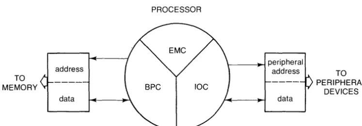
In addition to the processors, the hybrid also contains an I lObus which is controlled by certain instructions. The 110 bus has an "address" part and a "data" part. Some of the instructions (it is indicated which ones) cause an "input cycle" to occur on the bus, which means that an address is given to the address part of the bus, and the data which appears on the data part is considered to be input. Other instructions cause an "output cycle" , which means that the data is to be output to the given "address".
TO MEMORY
Registers
PROCESSOR address datal---~ peripheral
address TO
data
PERIPHERAL DEVICES
Figure 4. Generalized Machine Architecture
The memory locations in the machine are addressed from 0 to 177777B. There are 32 memory locations which are addressed as if they were part of the computer read/write memory, but actually are part of the processor. These locations are called "internal registers". Each internal register has a specific location and has been given a name. As you will learn in "Symbolic Operations" (Chapter 4), these names have been reserved and cannot be redefined while using the assembly system.
The internal registers are
-Name A Ar2 B C Cb D Db Dmac Dmama Dmapa P Pa R R4 R5 R6 R7 Se Address (Octal) 0 20-23 1 16 13 17 13 15 14 13 2 11 3 4 5 6 7 Description Arithmetic accumulator BCD arithmetic accumulator Arithmetic accumulator Stack pointer
Block bit for byte pointer in C (use most significant bit only, read only) Stack pointer
Block bit for byte pointer in D (use second most significant bit only, read only)
DMA count register
DMA memory address register
DMA peripheral address register (use lower 4 bits only) Program counter
Peripheral address register (use lower 4 bits only) Return stack pointer
} 1/ 0 (Input/ Output) registers
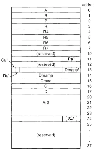
[image:38.618.101.475.93.223.2]Figure 5 is a map of where these registers lie. In addition to these registers; the addresses 258 through 378 are also registers, but are not (except for a few isolated cases) used in assembly programming. A B P R R4 R5 R6 R7 (i8S8iV8d)
~ (reserved)
I I
1 / Dmama
Dmac
C
D
Ar2
(reserved)
I
PalI
Dmapa1address o 1 2 3 4 5 6 7 10 11 12 13 14 15 16 17 20 21 22 23 Se1 24 I ,
25
37
Figure 5. Map of Lowest Memory
All of these registers can be referenced either by their names or by their actual addresses. The two methods are equivalent, though reference by name is recommended as a programming practice.
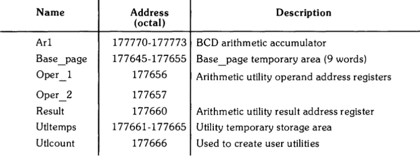
[image:39.617.233.421.174.470.2]In addition to the above internal registers, there are some "external" registers which reside in the computer read/write memory. They
are-Name Address Description
(octal)
Ar1 177770-177773 BCD arithmetic accumulator
Base _page 177645-177655 Base page temporary area (9 words)
-Oper 1 - 177656 Arithmetic utility operand address registers
Oper_2 177657
Result 177660 Arithmetic utility result address register
Utltemps 177661-177665 Utility temporary storage area
Ut1count 177666 Used to create user utilities
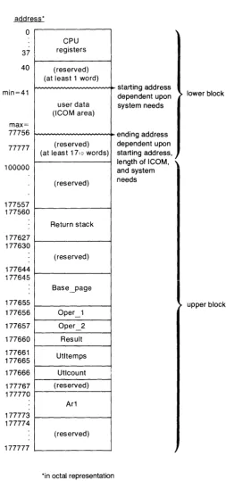
General Memory Organization
In order to find your way around the machine effectively, you should be aware of where things are stored in memory. Occasionally these areas can become considerations in your program-ming.
First in the memory come the internal registers. They were discussed above.
Next in the memory comes the ICOM area. The starting location is dependent upon system needs, but never lower than 41B. The size of the ICOM region depends upon the size desig-nated by the ICOM statement. Its maximum ending address is 77756B. This is the reason for the limitation on the size in the ICOM statement.
Next in the memory comes the area reserved for the system to store programs and the like. This area extends from the end of the ICOM region to 177644B.
[image:40.617.74.495.145.306.2]This area is followed by the registers in the read/write memory (see the list in the previous section) with a number of interspersed system-reserved areas.
address* o 37 40 min=41 max= 77756 77777 100000 177557 177560 177627 177630 177644 177645 177655 177656 177657 177660 177661 177665 177666 177767 177770 177773 177774 177777
I
registers CPU (reserved) (at least 1 word)user data (ICOM area)
(reserved) (at least 17, a words)
(reserved)
I
Return stack (reserved) Base_page Oper_1 Oper_2 Result Utltemps Utlcount (reserved) Ar1 (reserved)
*in octal representation
starting address dependent upon system needs ending address dependent upon starting address, length of ICOM, \ and system needs
lower block
upper block
Figure 6. Memory Map
[image:41.623.216.470.96.637.2]Protected Memory
All of the reserved areas men tioned above are known as "protected memory". To give some measure of security to the operating system, it is advised that no attempt should be made to write or branch into these areas.
Access to certain portions of protected memory (e.g., BASIC variables) is provided by utilities within the assembly system. The user should access those areas only through the utilities.
Some measure of protection against access into these areas is provided during debugging. See the chapter entitled "Debugging" for a discussion of how this is done and the extent of the protection provided.
Base and Current Page
A concept that occasionally arises during discussion of the instructions and the assembler is that of the "page" , the "base" and "current" pages in particular.
A page is 1 024 words of memory.
The "base" page is a wrap-around page. It consists of the upper half of the last page in the machine (addresses 177000B to 177777B) and the lower half of the zero page (addresses 0 to 777B). This is the same as a page which runs from - 512 to
+
511, effectively "wrapping around" address O.During execution, the program counter (P) points to the address of the current instruction. The "current" page is those 1 024 words of memory centered upon the current instruction. There-fore, the current page is a continually changing page, extending from (P)- 512 to (P)+ 511.
Nesting of Subroutine Calls
Assembly language subroutines are called using the JSM instruction and exited using the RET instruction, both of which are described later in this chapter. Subroutine calls may be nested, just as they are in BASIC.
You are not free to use ali 40 words in the R stack, however. The operating system and ICALL require 5 words. Interrupt service routines (refer to Chapter 7 for more information on ISRs) require 10 words. Break points (refer to Chapter 8 for more information on the IBREAK statement) require 5 words.
Thus, 20 words are left for the nesting of user JSMs. Calling system utilities also requires some of these 20 words. Appendix F, Utilities, contains the information necessary to determine the number of words needed by the various utilities.
For example, the following program segment illustrates the use of the R stack space
-J.-_':-''':'':
L: _ .. _.:.. .; II
i"i=='":=·:.-1. =
_ . :ec ~_~t ~ ... .
-.-'._" .:.~ :;;'~ . . :: -._ . .;.' --;>:""; +(:='=;+-:L ::
Data Structures
It is common to access BASIC variables from an assembly language routine then retrieve the contents, manipulate them, or alter them. To be effective at it, you should be aware of how BASIC stores a value in each of its data types.
There are four data types in BASIC: full-precision numeric values, short-precision numeric values, integers, and strings. Each is stored in its own unique structure.
Integers
The simplest of the types is the integer. (Variables are declared as integers using BASIC's INTEGER statement.) An integer consists of a single word. Values between - 32 768 and
+
32 767 can be stored in the word. Negative values are stored in two's complement form. An integer looks like-15 14 OBit
I
i
"Sign Bit
Strings
Strings are the next simplest structure. A string is a succession of bytes, one character to a byte. A string may be of variable length. To be able to designate the length, the string is preceded by a word which contains the number of bytes in the string.
If a string has an odd number of bytes in it, then the left-over byte in the word containing the last character of the string is wasted. A typical string of length n looks like
-~~
n(length)
byte 1 byte 2 byte3 byte 4 byte 5 byte 6
byte n-2
I
byte n-1 byte nI
L-Full-Precision
t~umbersFull-precision numeric values are stored as 12-digit, BCD (Binary Coded Decimal), floating point numbers. They occupy four words each. The first word contains the sign of the exponent, a two's-complement IO-bit exponent, and the sign of the mantissa. The other three words contain the twelve mantissa digits, 4 to each word. The words look like this
-15 14 13 12 11 10 9 8 7 6 5 4 3 2 OBit
Exp: I I I I I I I I I I I I I I~an
Sign! Exponent o 0 0 0 0 Sign
01
(most significant digit) 02 03 04
05 06 07 Os
012
09 010 011 (least significant)
The exponent is always adjusted during arithmetic routines so that there is an implied decimal point following 01. Thus, every mantissa value looks like
-Short-Precision Numbers
Short-precision numeric values are stored as 6-digit, BCD floating point numbers. Unlike full-precision, they occupy two words each instead of four. The first word contains a 7 -bit exponent, the sign of the mantissa and the two most significant mantissa digits. The second word contains the remaining four mantissa digits. The words look like this
-15 14 13 12 11 10 9 8 7 6 5 4 3 2 OBit
EXP11
I I I I I
IMan
I I I I I I
Sign Exponent Sign 01 02
03
I
04 05 06
As with full-precision, the exponent is stored in two's complement form and the implied deci-mal point follows 01.
Machine Instructions
The machine instruction set underlying the assembly language system consists of 92 instructions, divided into eleven groups. The groups are
-Load/Store
Integer Math
Branch
Test/Branch
Test/ Alter /Branch
Shift/ Rotate
Logical
Stack
BCD Math
I/O
Miscellaneous
Operands
Operations placing values into registers or memory.
Operations involving integer arithmetic.
Operations altering the execution sequence unconditionally.
Operations altering the execution sequence, dependent upon some condition.
Operations altering the execution sequence and a value, de-pendent upon some condition.
Operations performing re-arrangments of the bits in the A or B register.
Operations performing logical functions on the A or B regis-ters.
Operations managing stacks.
Operations involving Binary Coded Decimal arithmetic.
Opera tions specifically involving I/O operations.
Some unclassifiable operations.
Most instructions require operands. These operands have general forms which they may assume.
For exampie, note the operands in the following
-A {location} may be either "relocatable" or "absolute" (see "Relocation" and "Symbolic Operations" in Chapter 4 for a full treatment of these types). If a relocatable {location} is used, the assembler generates machine code which uses "current page" addressing, and thus the {location} must be within - 512 words and
+
511 words of the instruction. If an absolute {location} is used, the assembler generates machine code which uses "base page" addressing (meaning it takes the address as an offset from location 0).An {address} is a {location} the same as above, except the intended location must be relocatable and within - 32 and
+
31 words of the current instructions.A {register} may be specified either through its absolute address or by its pre-defined symbol. The permissible registers are those with addresses between 0 and 7, inclusive. These are registers A, B, P, R, R4, R5, R6, and R7.
A number of instructions are followed by a {value}, which is a numeric expression usually in the range of 1 through 16. This {value} frequently indicates the number of bits involved in the operation. For example
-right-shifts the A register by 8 bits.
NOTE
Specifying the R4, R5, R6, or R7 registers (absolute locations 4 through 7) in an instruction causes an "I lObus
Indirect Addressing
Some instructions may also employ "indirect addressing". This is indicated by including the optional indicator ~ T, such as
-There is only one level of indirect addressing provided with the processor. Of course, if further levels are desired, it is possible to implement them on your own. Some flagging scheme could be adopted, for example. One approach could be to adopt the policy that the sign bit (bit 15) of a word would indicate further indirection, with the remaining bits being the value. In such an approach, a load accumulator instruction would become two instructions
-10 ISOURCE LDA A~I
20 I~~~RCE SAM *-1
Load/ Store Group
Use current contents as pointer
I If bit 15 set, indirection
This group of instructions allows transfers of data to take place. With the instructions below you can move information to and from the arithmetic accumulators (the A and B registers). You can also transfer the contents of one contiguous set of words in memory to another contiguous set.
Instruction
, T'R L . .!..!;. {I oca IOn t' } [ ~.I.
"J
LIIE {location} [~ IJ
::;T8 {location} [:; I]
::;TE {location} [~ 1]
... , "-. { I }
U._f':. va ue
>::FF~ {value}
Description
Loads register A with the contents of the specified location.
Loads register B with the contents of the specified location.
Stores the contents of the A register into the specified location.
Stores the contents of the B register into the specified location .
Clears (zeroes out) the specified number of words, beginning at the location specified by the A register. {value} must be an integer between 1 and 16.