2018 International Conference on Computer, Communications and Mechatronics Engineering (CCME 2018) ISBN: 978-1-60595-611-4
The Algorithm Research Based on Optimal Quadratic of Launch Control
Law Access Time of Folding Wing UAV
Rong LIU
1,*, Ying-feng XIAO
2and Heng ZHANG
31
UAV Research Institute, Nanjing University of Aeronautics and Astronautics, Middle and Small Size UAV Advanced Technique Key Laboratory of Ministry of Industry and Information Technology,
Nanjing, 210016, P. R. China
2
Panda HANDA Technology Co. Ltd of China Electronics Corporation, Nanjing, 210016, P. R. China
3
College of Automation Engineering, Nanjing University of Aeronautics and Astronautics, Nanjing, 210016, P. R. China
*Corresponding author
Keywords: Optimal Quadratic, Folding Wing, Unbalanced Torque, Access Time of Control Law.
Abstract. In order to solve the poor control problem in the launch control section of folding wing UAV, which is caused by the booster rocket step torque disturbance and wing rocket rotation torque disturbance, the optimal state control algorithm based on optimal quadratic is used to calculate the time range of the control law accessing flight control system, united in the simulation test, the precise time of the control law accessing flight control system to control the rudder finally is determined. Under the optimal control scheme, flight control system can overcome the oscillation in the shortest time and resume the steady state. Through the validation of simulation and experimental, the optimization algorithm makes the effects of the double torque disturbance be smaller, successfully solves the control problem of folding wing UAV during emission, and ensures the high quality of launch control and flight control of UAV.
Introduction
With the miniaturization, integration, intelligent of the avionics and the improvement of the plane load capacity, unmanned attack plane enters the combat aircraft rank of the cluster interference blinding and the fast attack or damage [1]. Thus, in order to the realize the combat mode of strategic significance, it becomes an urgent task to rapidly develop the cluster emission unmanned aerial vehicle (UAV).
At present, the typical aircrafts using cluster emission technique at home and abroad are "Hobbit" made in Israel and the a certain type of UAV [2-3] developed by the Northwestern Polytechnical University. In the two UAVS, the width of launch container is limited by the wing span width of fixed-wing UAV. In consideration of the long-distance transportation, the width of the launch vehicle is limited, thus the amount of loading UAV is limited. If both sides of the aileron are folded, it can greatly reduce requirement of launch container width limited by span width. Currently there are some UAVS with folding wing, such as SU - 33 and a series of shipboard aircraft. However, SU-33 need people to help expanding the wing before the launch, spreading control automatically of wings cannot be realized, and it wastes a lot of manpower, material resources and working time [4]. A new type of folding wing UAV has been developed by Nanjing University of Aeronautics and Astronautics. The wing of this new UAV can be spread automatically by the wing rocket, after the UAV is launched out of the container. Under this new technology, launch interval is shortened in ten seconds, and which can achieve rapid build-up and greatly improve the battle fire density and degree of automation.
speed during the spreading process of outer wings. Thus, the control of UAV will be disturbed by the strong torque [5-6]. If the control law algorithm accesses system too early, the torque disturbance caused by spreading wings is too strong, and the rudder cannot play an effective role. If the control law algorithm accesses system too late, the step disturbance influence caused by the imbalance torque of booster rocket is strong, which will make system oscillation period to be longer, and it is not helpful for the follow-up control system. Therefore, how to select the time of accessing system for the appropriate control law and reduce the disturbance influence of step torque and imbalance torque, becomes the key technique of the flight control system in the launch control phase.
Establishment of UAV Model and Interference Model
Establishment of UAV Model
The flight control system of conventional UAV is the control system with multi channels, in which the input is the state variable of UAV collected by the sensors and the output is the control variable of UAV state equation—output value of each rudder. The linear equation of UAV can be calculated by the small perturbation linearization method, and the state equation can be expressed as:
BU AX
X
(1) In equation (1), X is the state variable of the UAV, U is the control variable of UAV, A is the state matrix, B is the input matrix, A and B are obtained from the UAV aerodynamic parameters.
In order to simplify the design of flight control system, according to the symmetry of the UAV along the longitudinal plane, the flight control is divided into longitudinal control channel and lateral control channel which are relatively independent. The angle, height and speed of UAV can be stabilized and controlled by the longitudinal control channel. The flight-path angle, roll angle and yaw distance of UAV can be stabilized and controlled by the lateral control channel.
For UAV longitudinal channels, there is:
T
Z H
V
X1 [ ]
T P Z
U1 [ ] (2)
1 1 1
2 2 2
1
2 3 2 3 2
3 3 3 3 3
4 4 1 4
0 0
1 0
0 0 0 1 0
0
0 0
V V
V V
V
n n n
n n n
A
n n n n n n n n n n
n n n n
(3)
2
1
2 3
3
0 0
0
0 0
0
0 0
Z
Z Z
n
B
n n n
(4)
For UAV lateral channel, there is:
T Y X
1 1
1
2 2 2
2
3 3 3
1
0
0
0 1 0 0
x
x y
x y
n n n
n n n
A
n n n
1
2 2
2
3
0
0
0 0
Y
Z Y
Y
n
n n
B
n
(6)
Among these formulas: V is the variation of UAV speed; is the variation of attack angle;
is the variation of pitch angle; Zis the variation of UAV pitch rate; H is the variation of
UAV height; Zis the variation of UAV elevator rudder; p is the variation of UAV throttle
rudder; is the variation of UAV sideslip angle; X is the variation of UAV roll angle rate;
Y
is the variation of UAV yaw angle rate; is the variation of UAV roll angle; X is the
variation of UAV aileron rudder; Y is the variation of UAV yaw rudder.
Other parameters are the coefficients of the equation, which have certain relation with the known pneumatic parameters. By blowing test, UAV dynamic parameters can be obtained and the concrete values of all coefficients can be calculated.
Establishment of the Interference Model
At the early stage of the launch, the UAV control rudders of longitudinal and transverse are locked in a given position. Because of the imbalance thrust of two rockets and other interference factors, UAV rudders appear instantaneous step change, which affects the control system greatly. This interference has a certain relationship with the size of the step signal, which has a functional relationship with thrust error and time of booster rockets. During the spreading of folding wings, the force acted on the outboard wings is very complex, and it is difficult to find the calculating method which can meet the engineering application. Even in the wind tunnel, it is difficult to simulate the overload situation in the
launch process of rocket, and the outboard wing spreading disturbance torque My and the unbalanced
disturbance torque Mx are estimated only by recursive algorithm and the test data accumulated with
real emission mode.
The function between the outboard wing spreading disturbance torque and the time of expansion is shown, such as formula (7):
) (t G
My (7)
Thereinto, My gradually decreases with t increasing.
The function between the unbalanced disturbance torque and the time of expansion is shown, such as formula (8):
) (t J
Mx (8)
Thereinto, Mx gradually increases with t increasing.
x
M
and My have a great influence on the lateral channel, and the effect on the longitudinal
channel can be neglected. The effect of Mx and My will be considered as disturbance term added
into the lateral state equation, which is shown as formula (9):
) ( ) ( ) ( )
(t AX t BU t wt
X
(9)
Thereinto, w(t) is the disturbance term of Mx and My, and it can be considered as the system
Algorithm Design of Control Law Access Time Based on Optimal Control
Optimal Quadratic Algorithm
For the system without interference termsX AX BU
, the quadratic performance index is shown as formula (10):
0 0 0
1
( ) 2
T r
J x P t x
(10)
Among formula(10), t0 is the accessing time of control law, x0 is the state variables when time for
control law is accessed (the UAV state collected by the first sensors), P(t) satisfies the Riccati equation and the boundary conditions , shown as formula (11), (12) :
Q t P B BR t P t P A A t P t
P T T
) ( )
( ) ( )
( )
( 1 (11)
( )f T( )f P t P t
(12)
Thereinto, A and B are the parameters which is firstly obtained, tf is the time of the end, Q and R need to be selected artificially, and P can be calculated by Q and R. Q and R must meet the
conditions, the condition of 1: Q is symmetric nonnegative definite matrix, the condition of 2: R is symmetric positive definite matrices.
After getting P, the state feedback control law can be got, shown as formula (13):
) ( )
(k K X k
U (13)
There into:
1 T
KR B P (14) The control law is same in the system with disturbance and the system without disturbance. For the system with disturbance, the quadratic performance index is shown as formula (15):
0
0 0 0 0
1 1
( ) { ( ) ( ) }
2 2
f
t T
r
t
J x P t x tr
Q t P t dt(15)
0( ) ( ) ( )
T
Q t w t w t
(16) In the formula (15), the first item is the optimal performance index of the system without
disturbance, and the second item is the model of noise w(t), which is generated by its variance matrix
) (
0 t
Q
. Therefore, in order to make Jr to be minimum, 0
0
1
{ ( ) ( ) } 2
f
t t
tr
Q t P t dtmust be minimum [7-11].
Calculation Optimal Control Law
For the longitudinal channel and lateral channel, the matrix Q1, Q2 and R1, R2 are selected
respectively, in which the matrix must meet two conditions, the condition 1: Q1 and Q2 are the
symmetric nonnegative definite matrix, the conditions 2 : R1 and R2 are the symmetric positive
formula (14), then coefficient matrix K1 of the state feedback control law of longitudinal channel and
coefficient matrix K2 of the state feedback control law of lateral channel can be got.
Thereinto: 1 0 0 0
z
z z
K K K
,
2
0 0
0 0
x
y
x x
y y
K K
K
K K
.
Taking K1 and K2 into system, then the system control law can be got. The longitudinal channel
control law is shown as formula (17), and the lateral channel control law is shown as formula (18) and (19):
g
z zZ z
z
K
K
(17)
g
x xx x
x
K
K
(18)
y y y
y
y
K s
s
K
1 (19)
In the formula (17), z is the value of elevator rudder, is the value of pitch angle, g is the given
value of pitch angle, z is the value of pitch angle rate. In the formula (18), xis the value of aileron
rudder, the value of left aileron rudder is positive, the value of right aileron is rudder negative, is
the value of roll angle, g is given value of roll angle, x is the value of roll angle rate. In the
formula (19), y is the value of yaw rudder, y is the value of yaw angle rate.
Calculation of Launch Optimal Control Law Access Time
In order to make the quadratic performance index of the system to be minimum, Jr in the formula
(15) must be minimum. The formula shown as 0
0
1
{ ( ) ( ) } 2
f
t t
tr
Q t P t dtis a function of t0, and it must
meet the function shown as
0
0
0
1
{ ( ) ( ) }
2 0
f
t t
tr Q t P t dt
t
, so t0 is the best time range of control law
accessing system.
Simulation Results
In order to validate the optimal control law and the best time range of accessing the control system, simulation test is needed to be designed. The simulation test designed in this paper is divided into two parts: digital simulation and semi physical turntable simulation.
Digital Simulation Test
1
0.0277 0.5323 0.2465 0 0
0.0213 0.5757 0.0205 1 0
0 0 0 1 0
0.3206 7.2578 0.0013 0.4103 0
0.3454 3.9867 3.9352 1 0
A 1 0 0.0297 0 6.0135 0 B 2
0.3832 0.0733 1 0.3569 0.0572 3.2567 0.5876 0 18.4520 0.2121 0.5371 0
0 1 0 0
A 2 0 0.0576 73.33 13.61 0 15.69 0 0 B
Interference model is shown as follows:
0 0
0.0068(2 ) 0.0104 0.0232
( ) [0 0.5) ; ( ) [0.5 3]
0.0008(2 ) 0.0136 0.0032 )
0 0
0 0
0.0436 0.0032 0.0034
( ) (3 3.5] ; ( ) (3.5 )
0.016 0.004 0.004)
0 0
t t
w t t w t t
t t
t
w t t w t t
t
The power matrix of longitudinal channel is selected as: Q1 1.2I55, R1 0.6I22; and the
power matrix of lateral channel is selected as: Q2 1.6I4 4 , R2 0.8I1 1 , tf 3.5 ,
0 [0 0.5 0.5 1]
T
x
. Through the optimal control algorithm and according to the formula (11),
(12) and (14), P1 and P2 can be obtained respectively, shown as:
1
0 0 0 0 0
0 0 0.0005 0.0002 0
0 0 0 0 0
0 0 0.0998 0.0499 0
0 0 0 0 0
P , 2
0 0.0001 0.0006 0.0006
0 0.0022 0 0.0055
0 0.0019 0.0153 0.0156
0 0 0 0
P
. Finally the longitudinal
state feedback control law matrix can be got: 1 0 0 0
0 0 1.0 0.5 0
z
z z
K K K
. And the
lateral state feedback control law matrix can be got:
2
0 0 0 0.2 0 0.5
0 0 0.3 0.4
0 0 x y x x y y K K K K K .
Through the validation of digital simulation, the control law coefficient can be obtained: 1.0 Z K , 5 . 0 z z
K , Kx 0.5, 0.2
x
x
K
, 0.4
y
K
, 0.3
y
y
K
. With the help of MATLAB, the formula
shown as 0
3.5
0 2
1
{ ( ) }
2tr
t Q t P dtand 0 3.5 0 0 1 { ( ) ( ) }
2tr t Q t P t dt
t
the equation shown as
0 0
0 1
{ ( ) ( ) }
2 0
f
t
t
tr Q t P t dt
t
, then access time range of launch control law is
calculated as: 0.63t0 0.68.
Semi-physical Turntable Simulation Test
According to the system requirement, the wings of a certain type UAV are spread after UAV leaves the track about 0.5 seconds, and the entire process of spreading wings will last for 3 seconds. At this time, the UAV is in the condition of high acceleration.
Therefore, in the semi physical turntable simulation test, when UAV leaves the track, the roll
direction disturbance torque Mx 2Kgm is added, and gradually is increased toMx 5Kgm, in
order to simulate the unbalanced torque disturbance caused by the booster rocket step torque and wing
rocket rotation torque. The yaw direction disturbance torque My 12Kgm is added from 0.5
seconds to 3.5 seconds after UAV leaves the track, and gradually is reduced toMy 0Kgm, in order
to simulate torque disturbance caused by the nonlinear force of wing rocket.
According to the analysis of the experimental data, the best access time of launch control law is finally determined, which is 0.66 seconds. Under this access time, system can end the oscillation in the shortest time and resume stable state. After a certain type of folding wing UAV leaves the track, the value of rudders according to the control law algorithm are not output. From 0 seconds to 0.66 seconds after UAV leaves the track, the elevator rudder is locked in 4 degree, and the rudders of aileron and roll are locked in 0 degree. Until the UAV leaves the track about 0.66s, control law is accessed into the system to participate control.
Result Analysis
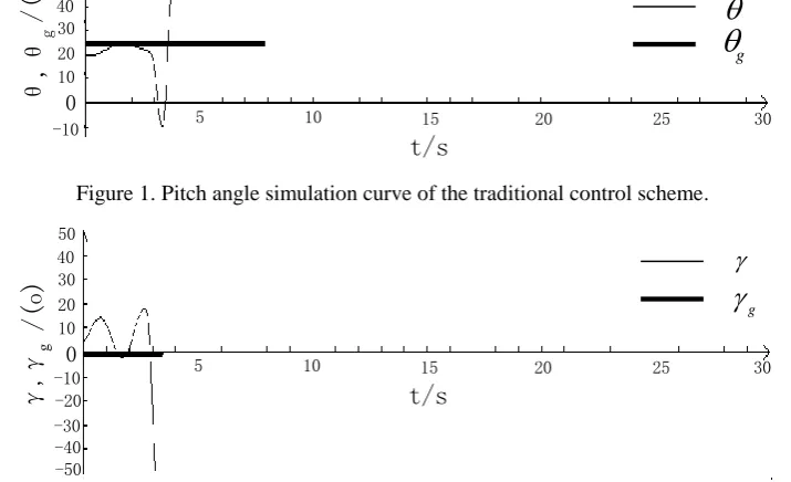
In this paper, under the traditional control scheme and the optimizational control scheme based on the algorithm of launch control law access time using optimal quadratic, simulation tests are carried out respectively. The simulation curves of traditional control scheme are shown in Figure 1 and Figure 2. And the simulation curves of optimizational control scheme are shown in Figure 3 and Figure 4.
0 30 40
20 10 50
/(
o
)
θ
,θ
g
-10 5 10 15 20 25 30
t/s
[image:7.595.131.472.500.580.2]g
Figure 1. Pitch angle simulation curve of the traditional control scheme.
0 30 40
20 10 50
-10
/(
o
)
γ
,γ
g
-20 -30 -40 -50
g
5 10 15 20 25 30
[image:7.595.120.478.508.726.2]t/s
0 30 40
20 10 50
5 10 15 20 25 30
t/s
g
/(
o
)
θ
,θ
[image:8.595.129.471.77.157.2]g
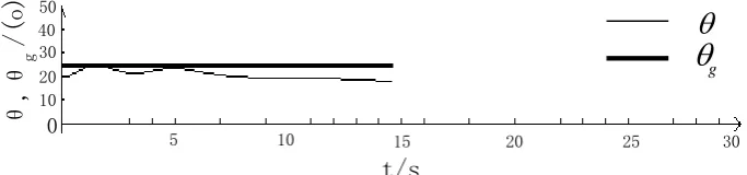
Figure 3. Pitch angle simulation curve of the optimizational control scheme.
0 30 40
20 10 50
-10 5 10 t/s15 20 25 30
/(
o
)
γ
,γ
g
g
[image:8.595.133.471.193.273.2]
Figure 4. Roll angle the simulation curve of the optimizational control scheme.
From the comparison of Figure 1, Figure 2 and Figure 3, Figure 4, under the traditional control scheme, when wings are spread, because of the influence of all kinds of complicated interference, attitude angle changes strongly and deviates from the given angle greatly, and attitude angle rate also changes strongly. These actors eventually cause the system to be unstable trend and become oscillation even divergence. Under the optimizational control scheme, control output and the error of given values are very small and the angle rate feedback also plays a good role, so the system can quickly return to a stable state after being disturbed. In the UAV launch segment, the optimizational control scheme can make the control precision of UAV launch period achieve the following indexes:
the deviation of attitude angle is shown as
1 ,
2
. Therefore, the optimizational control scheme can fully guarantee the UAV stability.
Conclusions
A new optimization algorithm of launch control law access time, for folding wing UAV, is provided in this paper. This optimization algorithm can reduce the influence of step torque disturbance and rotation torque disturbance to be smaller. The optimization algorithm of launch control law access time based on optimal quadratic, successfully solves the control problem in launch segment for folding wing UAV, simultaneously ensures high quality of launch control and flight control. The successful research of the optimizational control scheme based on this new optimization algorithm, has significant military value. This method has been used successfully in the UAV, which fills the blank of intelligent control for folding wing UAV in launch segment at home and abroad. And this new method promotes the development of UAV with fast combat capability.
Acknowledgements
Foundation items: Supported by Advanced Research Foundation of the General Armament Department (51325010601), the Fundamental Research Funds for the Central Universities (No. NS2018059).
References
[1] Liao Bo, Yuan Changsheng, Li Yongze. Development status and key technology of folding-wing unmanned air vehicle [J]. Journal of Mechanical Design, 2012, 29(4):1-5.
[3] Jamey D Jacob, Suzanne W Smith. Design limitations of deployable wings for small low altitude UAVs [C]//47th AIAA Aerospace Sciences Meeting Including, The New Horizons Forum and Aerospace Exposition, Orlando, Florida, AIAA 2009-745:516-525.
[4] Matthew P Snyder, Brian Sanders, Franklin E Eastep, et al. Vibration and flutter characteristics of a folding wing [J], Journal of Aircaft, 2009, 46(3):791-799.
[5] Lv Shengli, Liu Pin, Yang Guangjun, et al. Experimental study of aerodynamic characteristics in folding wing unfolded deployment process [J]. Flight Dynamics, 2013, 31(1):80-83.
[6] Wang Huaguang, Wanghua, Inspection requirements of the design of the folding wing flying device [J]. Cruise Missile, 2009(6):36-39.
[7] Ko S, Bitmead R R. Optimal control for linear systems with state equality constraints [J]. Automatica, 2007, 43(9)1573–1582.
[8] Liu Tianhua, Lee Yungching, Chang Yih-hua. Adaptive controller design for linear motor control system [J].IEEE Trans on Aerospace and Electronic Systems, 2004, 40(2):601-616.
[9] Hu Shousong, Wang Zhiquan, Hu Weili. Optimal Control Theory and System [M]. The second edition.beijing: Science Press, 2005: 162-207.
[10] Nikolaos K, Costas K, Costas T, et al. Optimal controller tuning for nonlinear process [J]. Automatica, 2005: 41(1), 79–86.
[11] Li X R, Zhu Y M, Wang J, et al. Optimal linear estimation fusion, Part I: unified fusion rules [J]. IEEE Transactions on Information Theory. New York: IEEE, 2007, 49(9): 2192–2208.
[12] Zhang Dengfeng, Gao Jinyuan. Aircraft flight control law/ Multidisciplinary design optimization for handling efficiency [J]. Journal of Beijing University of Aeronautics and Astronautics, 2008, 34(5): 491-494.