2018 International Conference on Computational, Modeling, Simulation and Mathematical Statistics (CMSMS 2018) ISBN: 978-1-60595-562-9
Image Processing Technology in Fog and Haze Environment
Based on Retinex Theory
Jie WANG, Ming-hua WAN
*, Yu-hui XU, Ding-nan FAN,
Ruo-yu LING
and Hao-ming YIN
School of Technology, Nanjing Audit University, Nanjing, 211815, China
*Corresponding author
Keywords: MSR, Image enhancement, Retinex theory, Haze image.
Abstract. For the multi-scale Retinex algorithm (MSR), the image contrast and image information is not ideal enough. In this paper, we propose an algorithm of image haze removal based on the fusion of dark prior and Retinex theory. Firstly, the algorithm of dark primary color is used to restore the haze image. Then, the multi-scale Retinex algorithm is applied to enhance the haze. Finally, the average value of brightness, standard deviation, entropy, mean square error, and peak signal-to-noise ratio were used as evaluation criteria for image enhancement. The simulation results of Matlab software show that the smog image processed by this algorithm has increased image contrast and more image information. We conduct experiments to prove that the proposed algorithm can provide a better representation.
Introduction
Fog is one of the most common natural phenomena [1-2]. Even in sunny weather, due to the presence of water molecules in the air, when you observe distant scenery, you will feel a thin layer of fog. The existence of haze is due to the presence of a large amount of smoke and dust in the air, so that the turbidity of the air is increased. In recent years, with the rapid development of our country, the occurrence of ash weather has greatly increased. The presence of fog and haze results in a decrease in atmospheric visibility, and the contrast of the captured image of the optical imaging device is degraded and even blurred, making it difficult to obtain image feature information. In addition, haze image enhancement is to enhance useful information in images, and remove redundant information in images, and enhance the image contrast by image enhancement, which is more prominent and more consistent with people's visual characteristics. Image enhancement is not to add some information on the basis of original information, but to highlight important information in the image for making it easier to be identified. Therefore, it is of great significance to enhance the research of image captured in haze [3].
The rest of this paper is organized as follows. Section 2 reviews the relevant knowledge. Section 3 presents the experimental results. Finally, the conclusions are drawn in section 4.
The Relevant Knowledge
Local Retinex algorithm theory main content is that a pair of images can be divided into light and reflection. The advantage is better able to get rid of lighting part of the image, so as to get the details of the image is reflected in an image in a haze of the two methods. The advantage of this approach is to minimize the amount of computation in the local algorithm, because it is a complex algorithm, and now it is only necessary to do a very simple addition and subtraction. Local Retinex algorithms are classified into three categories, including single scale Retinex algorithm, multi-scale Retinex algorithm and multi-scale Retinex algorithm with color restoration.
SSR Single Scale
The single-scale Retinex algorithm is an improvement and implementation of the center - around the Retinex algorithm. It use ƒ(x, y) function (usually low-pass filter function) convolve with the original image. Thereby filter the reflection part of the image from the original image, leave the irradiation part.
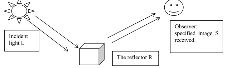
[image:2.612.125.489.338.447.2]The principle of this algorithm is that the original image S(x, y) = R(x, y) * L (x, y), which R(x, y) represents the reflected image and L (x, y) represents the incident. I'm going to illustrate this with a picture. As shown in the following figure 1:
Figure 1. The principle of SSR algorithm.
The incident light shines on the reflector, and after reflection, a reflected light enters the human eye, forming an image. In the process, R(x, y) represents the reflection property of the reflector that the intrinsic property of image, that we should keep it to the maximum extent. However, L(x, y) represents the incident light image, which determines the dynamic range that the image pixel can achieve, which we should try to remove it.
In general, we assume that the irradiation image is an image of space smoothness. For the above formula, we can take the logarithm of both sides, then we will get the results that
logS x, y logR x, y log L x, y (1) Then we can reason
logR x, y logS x, y log F x, y ⊙ S x, y (2) F(x, y) represents the central surround function, namely
F x, y λe (3) Symbol ⊙ is on behalf of a convolution operation, and logR x, y is the output image which can considered as R(x, y).Then, the sigma in the center wrap function must satisfy
∬ F x, y dxdy 1, c is a Gaussian round scale.
Observer:
specified image S received.
Incident light L
MSR Multi-scale
The multi-scale Retinex algorithm is a superposition of the weights of the single-scale Retinex algorithm on multiple scales. The MSR algorithm which divides the color into channels has emerged
for the problem that SSR is not suitable for processing color images. It is based on the development of SSR, and has the advantage of maintaining high fidelity of the image and compressing the dynamic range of the image. It can also achieve color enhancement, color constancy, local and global dynamic range compression, and defogging.
The basic formula for MSR is as follows:
r x, y logR ∑ 𝜔 𝑙𝑜𝑔𝑆 𝑥, 𝑦 log 𝐹 𝑥, 𝑦 ⊙ 𝑆 𝑥, 𝑦 (4)
According to this formula, we can know that when k=1, MSR degenerates to SSR, and K is the number of Gaussian center surround functions. In general, when using this algorithm to estimate the light image, it is assumed that the initial light image is smooth. But the actual situation is not the case, at the edge of the area where the brightness is very different, the image light changes and does not change slowly. So in this case, the Retinex enhancement algorithm will produce halo problems in the enhanced image of regions with large differences in brightness. MSRCR Multi-scale Retinal Enhancement with Color Recovery Because of the color of image with enhancement of multi-scale Retinex algorithm has some distortion, it does not meet the people's visual characteristics. In order to improve this defect, multi-scale Retinex algorithm with color restoration is produced, its principle is based on multi-scale Retinex algorithm. On this basis, it adds the color recovery parameters C that can improve color. We can first enhance the multi-scale Retinex algorithm on the haze image. The improved algorithm is as follows: 𝑅 𝑥, 𝑦 𝐶 𝑥, 𝑦 𝑅 𝑥, 𝑦 (5)
𝐶 𝑥, 𝑦 𝑓 𝐼 𝑥, 𝑦 𝑓 ∑ , , (6)
𝑓 𝐼 𝑥, 𝑦 βlog 𝛼𝐼 𝑥, 𝑦 𝛽 𝑙𝑜𝑔 𝛼𝐼 𝑥, 𝑦 𝑙𝑜𝑔 ∑ 𝐼 𝑥, 𝑦 (7)
𝑅 𝑥, 𝑦 𝐺 ∙ 𝑅 𝑥, 𝑦 𝑂 (8) According to the above formula 5, we can see that this algorithm is based on the MSR algorithm with color restoration factor C. Where Ci in formula 5 represents the proportion of the color factor in the i-th color channel, and the ƒ() function in formula 6 represents the mapping function of the color space. In the formula 7, α represents the controlled nonlinear intensity, and β represents the gain constant. The final formula 8, G represents the gain, and O represents the deviation Offset. With C in the algorithm, we can adjust the proportion of the three color channels to achieve a clearer image in the relatively dark area, to make up for the MSR algorithm to make the image color distortion. For this reason, through the MSRCR, there is a formula 8 whose role is to modify the pixel from the logarithm domain r(x, y) to the real-valued domain R(x, y).
Experimental Results and Analysis
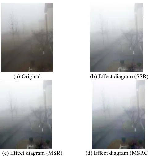
Example one:
(a) Original (b) Effect diagram (SSR)
[image:4.612.189.429.75.327.2]
(c) Effect diagram (MSR) (d) Effect diagram (MSRCR) Figure 2. A comparison of different diagrams in example one
Example two:
(a) Original (b) Effect diagram (SSR)
(c) Effect diagram (MSR) (d) Effect diagram (MSRCR) Figure 3. A comparison of different diagrams in example two.
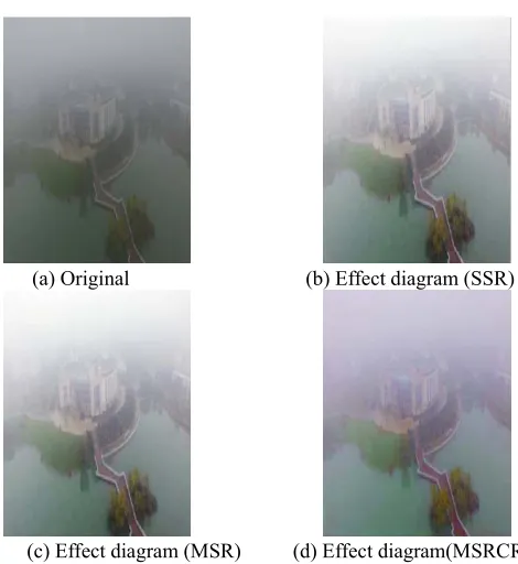
[image:4.612.183.431.358.612.2]Example three:
(a) Original (b) Effect diagram (SSR)
[image:5.612.189.424.72.328.2]
(c) Effect diagram (MSR) (d) Effect diagram(MSRCR) Figure 4. A comparison of different diagrams in example three.
Conclusion
Besides, we also found on the way to the debugging of the MSRCR algorithm that the technology is prone to halo at the edge where the light changes violently. At the same time, we found that the algorithm needs to calculate a large amount of data, so these defects will be one of the contents we will study later.
Acknowledgment
This work is sponsored by the college students' Innovation Fund(201711287060X), the National Key R&D Program grant No. 2017YFC0804002, the National Science Foundation of China under grant No. 61462064, 6177227 and the China Postdoctoral Science Foundation under grant No. 2016M600674, the Natural Science Fund of Jiangsu Province under Grant BK20161580, BK20171494.
References
[1]Bonomi, Flavio, et al. "Fog computing and its role in the internet of things." Edition of the Mcc Workshop on Mobile Cloud Computing ACM, 2012: 13-16.
[2]Ziyin Zhang, et al. "The Fog/Haze Medium-range Forecast Experiments Based on Dynamic Statistic Method." Journal of Applied Meteorological Science (2018).
[3]Huiming Li, et al. "Chemical partitioning of fine particle-bound metals on haze–fog and non-haze–fog days in Nanjing, China and its contribution to human health risks." Atmospheric Research 183(2017): 142-150.
[4]Land, E.H. "Recent Advances in Retinex Theory." Vision Research 26.1(1986): 7.