631
BELBIC BASED HIGH PERFORMANCE IPMSM DRIVE FOR
TRACTION
1A.SHAKILABANU, 2Dr.RSD.WAHIDABANU
1
Department of Instrumentation and Control Engineering ,Sethu Institute of Technology, Virudhunagar, Tamilnadu, India
2 Principal, Govt. College of Engineering Salem, Tamilnadu, India
E-mail: 1banushakila_a@yahoo.co.in, 2drwahidabanu@gmail.com
ABSTRACT
This paper proposes a brain emotional learning based intelligent controller (BELBIC)for Interior Permanent magnet synchronous motor (IPMSM) drives used for traction application. The IPMSM is a suitable motor for traction because of its brushless, wide constant speed-power region and low power-loss operation. The operation of the BELBIC is based on the emotion processing mechanism in the brain. This intelligent control is stimulated by the limbic system of the mammalian brain. Dual feedback and online tuning of emotional controller assures enhanced performance of the drive system. Dual loop adjustable speed drive system is proposed in this paper for traction application. The conventional PI controller controls the speed but does not guarantee the stability of the machine during the load variation. PI controller makes the system unstable by windup action. In this paper novel methods such as the Fuzzy PI controller and BELBIC are proposed to improve stability. Current is controlled by PI controller and speed is controlled by Fuzzy PI controller and BELBIC. Speed and torque performance of the machine is improved by the Fuzzy PI controller and BELBIC compared to conventional PI controller in the IPMSM drive system.
Keywords: PI, IPMSM, PWM, Fuzzy PI controller and BELBIC
1. INTRODUCTION
Interior Permanent Magnet Synchronous Motors (IPMSM) fed by PWM inverters are widely used for industrial applications, especially servo drive applications [12],[22] in which constant torque operation is desired. In traction and spindle drives, on the other hand, constant power operation is desired. The inherent advantages of these machines are light weight, small size, simple mechanical construction, easy maintenance, good reliability, and high efficiency. Generally speaking, the applications of the IPMSM drive system [19] include two major areas: the adjustable-speed drive system and the position control system. The adjustable-speed drive system has two control-loops: the current loop and the speed loop. In general, the research has focused on improvement of the performance related to current loop, speed loop, and/or position loop[17].
The IPMSM drive system has been controlled using a PI controller due to its simplicity. Azizur Rahman M et al., 2003 examined IPMSM using PI controller which results in reduced steady state error. However,
632 implement a simple, effective and low cost system.
BELBIC was introduced [15] as a controller based on the computational model of the limbic system of the mammalian brain. In the past few years this controller has been utilized in control devices[16] and drives [24] for several industrial applications. So Artificial Intelligence based BELBIC is proposed to limit the overshoot and to reduce the settling time. It has the advantage of less processing time.
2. MATHEMATICAL MODEL OF IPMSM
The mathematical model of IPMSM is similar to that of wound rotor synchronous motor [20]. The following assumptions are considered in the model [18],[21]
1. The induced EMF is sinusoidal. 2. Eddy currents and hysteresis losses
are negligible.
3. Saturation is neglected.
With these assumptions, the stator d, q axis equations of the IPMSM in the rotor reference frame are [3],[7].
Uq=Rsiq+Lqpiq+ωrLdid+ωrΨf (1)
Ud=Rsid+Ldpid-ωrLdiq (2)
Also flux linkage equation can be written as [7]
Ψd=Ldid+Ψf (3)
Ψq=Lqiq
(4)
where,
Ud and Uq are the d, q axis voltages,
id , iq are the d, q axis stator currents,
Ld, and Lq are the d, q axis inductances,
Ψd and Ψq are the d, q axis stator flux
linkages,
Rs is the stator winding resistance per phase
ωr is rotor electrical speed .
The electro mechanical torque is given by
Te=(3/2)(P/2)[Ψfiq–(Ld–Lq)idiq] (5)
where Pis the number of poles, TL is the load
torque, B is the damping co-efficient, ωm is the
rotor mechanical speed, J is the moment of inertia and p is the differential operator [1].
ωr=(P/2)ωm (6)
Where θm is the position angle of the rotor.
In order to achieve maximum torque per ampere and maximum efficiency, direct axis current component id is forced to be zero [4].
Te=(3/2)(P/2)Ψfiq (7)
The d, q variables are obtained from a, b, c variables through the park transform [10].
Uq=2/3[Uacosθ+Ubcos(θ–2П/3)+ Uccos(θ
+2П/3)]
(8)
Ud =2/3[Ua sinθ+Ub sin(θ–2П/3)+Uc sin(θ
+2П/3)] (9)
The a, b, c variables are obtained from the d, q variables through the inverse of the park transform [5],
Ua=Uqcosθ+Udsinθ (10)
Ub=Uqcos(θ–2П/3)+Udsin(θ–2П/3) (11)
Uc=Uqcos(θ+2П/3)+Udsin(θ+2П/3) (12)
3. SIMULATION MODEL OF IPMSM DRIVE
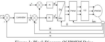
[image:2.612.325.534.591.676.2]The IPMSM drive system consists of speed loop, current loop, park transformation, PWM inverter and IPMSM motor. Block diagram of IPMSM drive is shown in figure 1.
Figure 1: Block Diagram Of IPMSM Drive
Speed loop has three inputs such as reference speed, measured speed and iq. Its output is
633 Error of reference speed and measured speed is given to the proposed/ PI controller. Output of speed controller is compared with the measured iq.
This error signal produces iq reference when it
passes through PI controller. Current loop has id*
and id as inputs. Its output is reference current id.
Error of id* and id is given to the PI controller to
produce reference current of id. Inverse Park
transformation receives the two reference current signals from speed loop and current loop. It converts that current id and iq into ia ,ib & ic. The
Iabc produced by inverse park transformation is the
reference current for Pulse Width Modulator. PWM inverter consists of a Hex bridge IGBT inverter and PWM generator. PWM generator receives reference signal from inverse park transformation. This signal is compared with the carrier signal and produces 3 pulses. These pulses are used to trigger the upper switches in the three arms. The pulse to the upper switch in the arm is inverted and given to the lower switch in the arm. From the inverter three phase voltage is taken out.
4. SPEED CONTROLLER
Set speed of the machine is achieved by optimum tuning of controller in a speed control loop. Performance of IPMSM drive using various controllers are analyzed in this paper. Fuzzy PI and Brain emotional learning based intelligent controller are proposed and compared with the conventional PI controller.
4.1 PIController
[image:3.612.319.499.562.688.2]The conventional PI controller is the simplest method of feedback control and widely used in industries. Proportional plus Integral Controller increases the speed of response. It produces very low steady state error. This is because derivative action is more sensitive to higher-frequency terms in the inputs.
Figure 2: Block Diagram Of PI Controller
Figure 2 shows the block diagram of PI controller. In this paper Speed error (e (t)) is taken as input to
PI controller and output is taken into the system. General equation of the PI controller is
u (t) = kp e (t) + ki ∫ e(t) (13)
e(t)= SP-PV (14)
e (t) is the error of actual measured value (PV) from the set-point (SP). kp is proportional gain,
ki is the integral gain and u(t) is the controller
output.
In this paper Ziegler Nichols’ method of tuning is implemented to find the optimum value of Kp &
Ki values. In an IPMSM drive PI controller is
used in both loops such as speed loop and current loop. It is an optimum controller for the current loop. In case of speed loop it produces the high overshoot, long settling time and drop in speed while change in load.
4.2 Fuzzy PI Controller
The fixed value of Kp and Ki in a PI controller
produces the high overshoot, settling time and speed drop during a change in load. Online tuning of Kp and Ki in a PI controller can conquer this
problem. It necessitates the Fuzzy PI controller for online tuning of Kp and Ki.
In a Fuzzy PI controller Fuzzy logic module is considered as an auto tuning module for parameters Kp and Ki in PI controller. The Fuzzy
PI controller is considered the major contribution of this research [9] ,[11],[21]. The fuzzy inference of fuzzy PI controller is based on the fuzzy associative matrices. The calculation of the speed of the controller is very quick, which can satisfy the rapid need of the controlled object. The block diagram of control system is shown in Figure 3.
[image:3.612.92.322.607.677.2]634 The control algorithm of traditional PI controller can be described as
u (k) = kpe (k) + ki ∫ e(k)
where, kp is the proportional gain, ki is the
integral gain and e (k) is the speed error.
The design algorithm of Fuzzy PI controller in this paper is to adjust the kp and ki parameters
online through fuzzy inference based on the current speed error e and error change rate ec to make the control object attain the good dynamic and static performances.
Speed error e and error change rate ec are used as fuzzy input and the proportional factor kp the
integral factor ki are used as fuzzy outputs. The
degree of truth of E and EC are configured as 5 degrees, all defined as {NB, NS,ZO, PS, PB}, where NB, NS, ZO, PS and PB represent negative big, negative small, zero, positive small and positive big respectively.
[image:4.612.310.523.75.201.2]The degree of truth of KP and KI configured as 4 degrees, are defined as {Z, S, M, B}, where Z, S, M and B represent zero, small, medium and big. The membership functions of E, EC, KP and KI are triangular distribution functions. The membership functions for each variable are shown in Figure 4, Figure 5 and Figure 6 respectively.
Figure 4: Fuzzy Membership Functions Of E And EC
[image:4.612.332.526.407.655.2]
Figure 5: Fuzzy Membership Functions Of KP
Figure.6: Fuzzy Membership Functions Of KI
The principle of designing fuzzy rules is that the output of the controller can make the system output response dynamic and static performances optimal. The fuzzy rules are generalized as table I and table II according to the expert experiment in the PMSM servo system and simulation analysis of the system. The Mamdani inference method is used as the fuzzy inference mode. The inference can be written as
"IF E is NS AND EC is PS THEN KP is S, KI is M". KP and KI are written the same as 25 fuzzy condition statements. The MIN - MAX method of fuzzification is applied. The weighted average method is adopted for defuzzification.
TABLE 1: The Control Rules For Kp
TABLE 2 : The Control Rules For Ki
The fuzzy PI controller reduces the overshoot, settling time and drop in speed during load change. Even though it produces some overshoot which should be reduced to improve the
e NB NS ZO PS PB
NB Z Z Z Z Z
NS M M M M M
ZO B B Z B B
PS S M M M M
PB Z S B B B
E
NB NS ZO PS PB
NB B B B B M
NS M B S S S
ZO M B Z S B
PS S S S S S
[image:4.612.90.283.448.601.2]635 performance of drive, it necessitates the simple and effective artificial intelligent controller.
4.3 BELBIC Controller
To enhance the speed performance a controller with less processing time, easy and effective control BELBIC is proposed in this paper. It is proposed to reduce the overshoot, settling time and drop in speed during change. It can be achieved by proposing BELBIC because it is a dual feedback controller. PI and Fuzzy PI are single feedback controllers.
BELBIC receives speed error of machine as one of the feedbacks and the BLEBIC output as another feedback. It results in accurate tuning of controller based on the present state.
[image:5.612.97.280.382.473.2]BELBIC is based on the architecture of the "Limbic System" of the human brain. The limbic system is responsible for the emotional learning in human beings. Figure 7 shows the block diagram of BELBIC controller.[27]
Figure 7: Block Diagram Of BELBIC
BELBIC is a simple composition of the Amygdala and Orbitofrontal cortex in the brain. A simple limbic system of the brain is shown in Figure 8.
Figure 8: Limbic System Of Brain
Pre-processing on sensory input signals such as noise reduction or filtering can be done in Thalamus. The emotional evaluation of stimulus signal is carrying out through the Amygdala, which is a small part in the medial temporal lobe in the brain. As a result, this emotional mechanism is utilized as a basis of emotional states and reactions.
At first, Sensory Input signals are going into Thalamus for pre-processing on them. In this paper speed error is considered as Sensory input. Then Amygdala and Sensory Cortex will receive their processed form and their outputs will be computed by Amygdala and Orbitofrontal based on the Emotional Signal received from the environment. Final output is the subtraction of the Amygdala and Orbitofrontal Cortex. One of the Amygdala’s inputs is called Thalamic connection and calculated as the maximum overall Sensory Input S as in equation (15). This specific input is not projected into the Orbitofrontal part and cannot by itself be inhibited and therefore it differs from other Amygdalas' inputs.
Ath=imaxSi (15)
Every input is multiplied by a soft weight V in each A node in Amygdala to give the output of the node. The O nodes behaviors produce their output signal by applying a weight W to the input signals as well as A nodes. To adjust the Vi difference between the reinforcement signal rew and the activation of the A nodes is been made use. For tuning the learning rate the parameter is used and it is set to a constant value. As shown in equation (16) Amygdala learning rule is an example of simple associative learning system, although this weight adjusting rule is almost monotonic. For instance, Vi can just be increased.
(16) Is the learning step in the Amygdala. The reason of this adjusting limitation is that after training of emotional reaction, the result of this training should be permanent, and it is handled through the Orbitofrontal part when it is inappropriate [6]. Subtraction of reinforcing signal from previous output E makes the signal of reinforcement for O nodes. To put it in another way, comparison of desired and actual reinforcement signals in nodes O inhibits the model output. The learning equation of the Orbitofrontal Cortex is drawn in Eq. (17).
[image:5.612.94.233.528.591.2]636 figure 9.
Figure 9: Simulation Model Of BELBIC
Mathematics the Linear Model of BEL Controller is represented by Following Simplified Equations
A = GA.SI (18)
O=GOC.SI
(19)
) (20
)
(21)
MO=A–OC (22) where MO is Model Output, SI is
Sensory Input, ES is Emotional Sensor, A is
Amygdala Output, O is Orbitofrontal Cortex, is Learning rate of Amygdala, P is Learning rate of Orbitofrontal cortex, GA is Gain for Amygdala ,
GOC is Gain for Orbitofrontal Cortex. Based on
the above equations mathematical model of BELBIC is formed. Since BELBIC is purely formed by the arithmetic equations it is ease to implement and consumes less processing time
5. SIMULATION RESULTS AND DISCUSSIONS
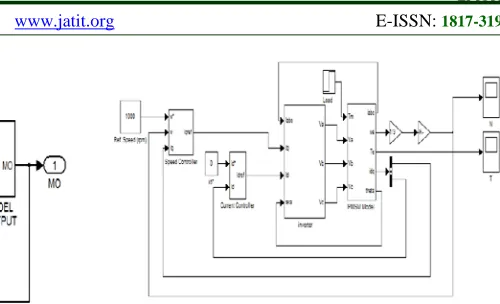
IPMSM dive is simulated using MATLAB/Simulink. IPMSM dive is analyzed using conventional PI controller. Then the same system is analyzed with Fuzzy PI controller and BELBIC. For the analysis load changes during run time. Reference speed and load are same for all PI, Fuzzy PI controller and BELBIC.
[image:6.612.266.516.71.223.2]The simulation model of IPMSM drive is shown in figure 10
Figure 10: Simulation Model Of Ipmsm Drive
The parameters of IPMSM used in this simulation model are given in table 3,
Table 3 :Ipmsm Parameters
Parameters Value
Stator Resistance Rs 1.4 Ω
Direct axis inductance Ld 6.6 mH
Quadrature axis inductance Lq 0.0116H
Moment of Inertia J 0.00176 Kg.m2
Rotor flux linkage φf 0.1546 Wb
Number of poles P 6
The results of IPMSM drive system using a conventional PI controller for speed is shown in figure 11 and figure 12.
Figure 11: Speed Response Of IPMSM Drive Using PI Controller.
[image:6.612.312.531.463.551.2] [image:6.612.309.527.589.689.2]637 The results of IPMSM drive system using proposed Fuzzy PI controller for speed is shown in figure 13 and figure 14.
Figure 13: Speed response of IPMSM drive using a Fuzzy PI controller.
Figure 14: Speed Response Of IPMSM Drive Using A Fuzzy PI Controller With Change In Load.
The results of IPMSM drive system using the proposed Emotional controller for speed is shown in figure 15 and figure 16.
Figure 15: Speed Response Of IPMSM Drive Using BLEBIC.
Figure 16: Speed Response Of IPMSM Drive Using BLEBIC With Change In Load.
[image:7.612.318.511.140.238.2]Comparison of speed response of IPMSM drive using PI, Fuzzy PI and BLEBIC controller is shown in figure 17.
Figure 17: Comparison Of Speed Response Of IPMSM Drive Using PI, Fuzzy PI And BLEBIC Controller
Speed response of IPMSM drive using BLEBIC at various speed references such as rated speed, above rated speed and below rated speed is shown in figure 18.
Figure 18: Speed Response Of IPMSM Drive Using BLEBIC At Various Speed References
The comparison of controller performance for speed ωm = 1000 RPM using PI, Fuzzy PI and
[image:7.612.93.293.268.370.2]BLEBIC controller are tabulated in Table 4.
TABLE 4: Comparison Of Controller Performance
Controller Peak oversho ot %
Steady state error %
Speed drop during load %
Settling time after load Sec
PI 11 0.6 0.4 0.04
Fuzzy PI 7 0.3 0.2 0.02
[image:7.612.320.476.338.472.2] [image:7.612.93.302.453.548.2] [image:7.612.319.518.574.698.2] [image:7.612.93.283.587.675.2]638 6. CONCLUSION
The essential characteristics of traction motor are accurate speed and stability during load change. In this paper three types of controllers PI, Fuzzy PI and BLEBIC are used as speed controllers in the IPMSM control and simulated in Matlab / Simulink. The performance of the system is analyzed with all three controllers and compared. From the simulation results it is clear that system performance is improved by Fuzzy PI and BLEBIC controller. The Fuzzy PI controller improves speed response compared to conventional PI controller in terms of overshoot, steady state error, drooping speed during load change and settling time after load change. BLEBIC controller is better than PI and Fuzzy PI controller in terms of stability. It quickly settles in speed after load change compared to other two controllers. Meantime BLEBIC controller produces the same response for rated speed, above rated speed and below rated speed of the machine. Simulation results show the robust performance of BELBIC against the disturbance. The BLEBIC controller based IPMSM drive is suitable for traction to operate in a wide speed range and frequent load changing condition.
REFERENCES
[1] Ambrish Pati Tripathi, Vikram Singh, Ankush Patidar, “Permanent Magnet Synchronous Motor Voltage Vector Control by Simulation”, International Journal of Scientific & Engineering Research., Vol.3,No.12, December 2012.
[2] Azizur Rahman M, Mahinda Vilathgamuwa D, Nasir Uddin M,“ Nonlinear Control of Interior Permanent-Magnet Synchronous Motor”, IEEE Transactions on industry
applications., Vol.39, No.2, March 2003.
[3] Bimbra P S, “Generalized Theory of
Electrical Machines”, Khanna Publishers,
2002.
[4] Bhim Singh., B. P. Singh., Sanjeet Dwivedi., “DSP Based Implementation of Hybrid Speed Controller for Vector Controlled Permanent Magnet Synchronous Motor Drive”, IEEE
ISIE., July 2006, pp. 2235-2241.
[5] Davendra Yadav, Sunil Bansal, Munendra Kumar, “Design, Development & Simulation of Fuzzy Logic Controller to Control the Speed of Permanent Magnet Synchronous
Motor Drive System”, International Journal of Scientific Research Engineering &
Technology.,Vol.1,No.5,August
2012,pp.101-106.
[6] Dishore S V, Devdas G, “Simulation of PMSM Vector Control system Based on Propeller Load characteristic”,International Journal of Engineering Research &
Technology .,Vol.2,No.1,January 2013.
[7] Faiz J., Manoochehri M., Shahgholia Gh., “Performance Improvement of a Linear Permanent Magnet Synchronous Drive using Fuzzy Logic Controller”, Proceedings of the IEEE International Conference on Power
System Technology., 2010, pp.1-5.
[8] Fazlur Rahman. M, Md. Enamul Haque Lixin Tang, and Limin Zhong, "Problems Associated With the Direct Torque Control of an Interior Permanent-Magnet Synchronous Motor Drive and Their
Remedies", IEEE Transactions on Industrial
Electronics., Vol.51, No.4, August 2004,pp.789-809.
[9] Han Ho Choy and Jin-Woo Jung, “Discrete-Time Fuzzy Speed Regulator Design for PM Synchronous Motor”, IEEE transactions on
industrial Electronics., Vol.60, No.2, Feb
2013, pp. 600-607.
[10] Hyoung-Seok Kang, Cheon-Kyu Kim and Young-Seok Kim , “Position Control for Interior Permanent Magnet Synchronous Motors using an Adaptive Integral Binary Observer”, Journal of Electrical Engineering
& Technology., Vol. 4, No.2, 2009,Page
240-248.
[11] Kiran Boby, Ananthamoorthy N.P, “Simulation of PMSM Vector Control System with Fuzzy Self-adjusting PID Controller Using MATLAB”, International
Journal of Scientific and Research
Publications, Vol.3, No.3, March 2013.
[12] Krishnan R., “Selection criteria for servo motor drives”, IEEE Transactions on
Industrial Applications., Vol. IA 23, No.2,
March 1987, pp. 270-275.
[13] Krishnan R, “A Textbook of Electric Motor Drives Modeling Analysis and control”, New
york (Pearson Education Publisher
Company, 2003.
639 in flux and torque and fixed switching frequency”,IEEE Transactions on Power
Electronics,Vol.19,No.2,March
2004,pp.346 – 354.
[15] Lucas C., Shahmirzadi D, Sheikholeslami N “Introducing Belbic : Brain Emotional Learning Based Intelligent Controller”,
Intelligent Automation and soft computing,
Vol.10,No.1,2004, pp.11-22.
[16] Lucas, Caro, Milasi, Rasoul M. and Araabi, Babak N,Intelligent Modeling and Control of Washing Machine Using Locally Linear Neuro-Fuzzy (Llnf) Modeling and Modified Brain Emotional Learning Based Intelligent Controller, Asian journal of
control.,Vol.8,No.4, Oct 2006,pp. 393-400.
[17] Mini Sreejeth, Madhusudan Singh, Parmod Kumar ; Prakhar Varshney, and Priyanka Sachdeva, “Implementation of supervisory control system for PMSM drive”, IEEE 5th India International Conference on
Power Electronics (IICPE), 2012, pp:1-6.
[18] Naruttam Kumar Roy ,Abdur Rafiq ,Rajib Kundu and B.C. Ghosh , “Intelligent Control of Interior Permanent Magnet Synchronous Motor Drive”, Journal of
electrical & electronics engineering.,Vol.9,
No.1January 2009,pp.781-789.
[19] Pillay P., Krishnan R., “Modelling Simulation and Analysis of Permanent Magnet Synchronous Motor Drives Part I: The Permanent Magnet Synchronous Motor Drive, IEEE Transactions on Industry
Applications ,Vol.25,No.2,April 1989, pp.
265-273.
[20] Pillay P., Krishnan R., “Modelling of Permanent Magnet Motor Drives”, IEEE
Transactions on Industrial Electronics.
Vol.35,No.4, November 1988, pp. 537-541. [21] A.ShakilaBanu, Dr.RSD.Wahidabanu.
“Comparative performance analysis of ipmsm Drive using anti windup pi and fuzzy piController”, Archives Des Sciences, Vol 66, No. 3;Mar 2013 ,pp:412-423.
[22] Rajat Varshney, Gunjan Gupta, “ Neuro-Fuzzy Based Speed Controller For Permanent Magnet Synchronous Motor”
,International Journal of Advanced
Research in Computer Science and
SoftwareEngineering.,Vol.2No.11,novemb
er 2012,pp.313-317.
[23] Ramana P, Santhosh Kumar B,Alice Mary K, Surya Kalavathi M, “Comparison of various PWM techniques for field oriented
control VSI fed PMSM drive ,Vol.2, No.7,July 2013,pp.2928-2936.
[24] Rebeiro .R.S. and Uddin, M.N., “Performance Analysis of an FLC-Based Online Adaptation of Both Hysteresis and PI Controllers for IPMSM Drive”, IEEE Transactions on Industry Applications.,
Vol.48,No.1,January 2012 ,pp.12 – 19.
[25] Rouhani, Hossein, Emotional learning based intelligent speed and position control applied to neuro fuzzy model of switched reluctance motor, Control and Cybernetics., Vol. 36,No.1, 2007.
[26] Uddin, M.N. and Rahman, M.A.,
“Development and Implementation of a Hybrid Intelligent Controller for Interior Permanent-Magnet Synchronous Motor Drives”,IEEE Transactions on Industry
Applications.,Vol.40,No.1,January
2004,pp.68-76.
[27]Guoyong Huang, Ziyang Zhen and Daobo Wang, “Brain Emotional Learning Based Intelligent Controllerfor Nonlinear system”,
IEEE conference proceedings on Intelligent Information Technology Application, 2008. IITA '08. Second International SymposiumIntelligent Information
TechnologyApplication on, 20-22 Dec.