DESIGN AND IMPLEMENTATION OF PID CONTROL
BASED BABY INCUBATOR
1ADHI KSATRIA THEOPAGA, 2ACHMAD RIZAL, 3ERWIN SUSANTO
1,2,3
Department of Electrical Engineering, Telkom University, Indonesia
E-mail: [email protected], [email protected],
3
ABSTRACT
The birth in early pregnancy and the lack of pregnancy nutrition can lead to birth problems and premature birth so that the baby easily induces hypothermia. Therefore, these babies require an incubator as a means of heating with standard temperatures between 32-37°C to help babies survive and to be able to adapt to the outside temperature. Nowadays, baby incubator on the market is using on-off control on the heating system. This condition has the disadvantage because the transient response time of the position of living long enough to off or conversely. This process certainly requires a large enough power to turn on and turn off the heater continuously. Therefore, we need a technology that is capable of controlling temperature conveniently. To overcome these problems we apply temperature control technique using Proportional-Integral-Derivative (PID). In this prototype, a designed baby incubator inside there is a two-piece box (top and bottom). Top box is used to put sensors and sensor display. While the bottom one is used to put electronic circuits, heater, and fan. The temperature sensor used is a room temperature sensor SHT11, while the temperature sensor for baby is NTC type. Baby incubator temperature changes and can be seen in the form of the temperature display on the display device. PID values are obtained by using the Ziegler-Nichols 1st method. Plant was fed by a unit-step input and the output response is obtained from the values of Kp = 13,827, Ki = 0,576, and Kd = 82,962. Each value is used into the heating system and the obtained time achievement is 4 minutes 44 seconds with set point at 32°C. Hopefully, in the future this system can be very useful for nurses and hospitals, as well as it can be redeveloped for enhancement purposes
Keywords: Baby Incubator, PID Controller, Ziegler-Nichols
1.
INTRODUCTIONPremature babies are babies born under the age less than 37 weeks weighing 2500 g. Premature babies have thin skin and shiny. Therefore, premature babies have difficulty maintaining a constant body temperature [1]. In order to grow like other normal babies, they should be immediately put in a baby incubator with temperature ranges between 32-37°C.
Baby incubators available on the market are using on-off control on the heating system to control the temperature in the incubator. This method has the disadvantage of the transient response time of the position of living long enough from the off position or conversely, and requires a large enough power to turn on and turn off the heater continuously.
To overcome this, we need a method to control the temperature in order to further conserve power, which is in this paper we use Proportional- Integral-Derivative (PID) control. PID control technique is
likely to get a response that has a high degree of stability so that it can more accurately control the temperature and save energy compared to using the on-off control [2].
The purpose of this research is to design a baby incubator system with the capability of monitoring and controlling its temperature effectively using PID control.
In this paper, we implement PID control to a baby incubator with following specifications: set point is set to 320 C, using ATmega328 in Arduino UNO R3 board, power maximum of the heater is 250 W and reference temperature is the temperature read from a temperature sensor SHT11.
2.
FUNDAMENTAL THEORYA. Baby Incubator
then the temperature in the incubator should be between 32°C. When weight less than 2500 grams, incubator temperature should be around 30°C. Incubator temperature will be reduced gradually every 10-14 days by one degree Celsius, so eventually the baby can adjust to the external environment [3][4].
B. Proportional, Integral, and Derivative (PID) Proportional, Integral, and Derivative (PID) is one method of automatically controlling a plant. It is one of the most famous and being used methods. PID is a control method that is derived from a combination of control methods Proportional, Integral, and Derivative [5].
Fig. 1. Representation Of PID Controllers [5]
The transfer function of the PID controller in parallel form as Fig 1.[6]:
Kd s s Ki Kp s E
s U
. )
( ) (
+ +
= (1)
+ +
= sTd
s Ti Kp s E
s U
. . 1 1 ) (
)
( (2)
where Kp is the proportional gain, Ki is the integration coefficient and Kd is the derivative coefficient. Ti is the integral time constant and Td is the differential time constant. These parameters are tuned in order to get best performance according to the design of the system [7].
C. The Ziegler-Nichols 1st Tuning Method
The tuning method of PID controller is based on Ziegler Nichols 1st tuning method. 1st method is based on plant response of unit-step input in the open-loop system. Plant that does not have a dominant integrator complex-conjugate poles, it will produce a curve in response to unit-step input as the shape of the S (S-shaped).
Fig. 2. Unit-Step Response Of A Plant [6]
[image:2.595.331.483.169.265.2]Plant response curve will then be used to find the delay time (L) and time constant (T) with the help of a tangent.
Fig. 3. S-Shaped Response Curve [6]
From the response curve, the value of Kp, Ti, and Td can be searched with the values of L and T that were obtained previously [6].
TABLEIZIEGLER-NICHOLS 1ST TUNING TABLES
AGAINST THE STEP RESPONSE OF THE PLANT [6]
D. Arduino Uno
[image:2.595.348.462.544.627.2]The Arduino Uno is a microcontroller board based on the ATmega328. Arduino UNO has 14 pins input/digital output (6 pins can be used as PWM outputs), 6 analog input pins, 16 MHz ceramic resonator, a USB connection, a power jack, an ICSP header, and a reset button [8].
Fig. 4. Arduino Uno Module [9]
E. SHT11 sensor module
in temperature 25°C and accuracy relative humidity measurements up to 3,5% RH [10][11].
Fig. 5. SHT11 Sensor And SHT11 Sensor Module [10][11]
F. NTC (Negative Temperature Coefficient) Sensor
Negative Temperature Coefficient (NTC) is a sensor that will shrink resistance value if the temperature around it rises and conversely when the temperature around the NTC decreases the resistance value would get bigger [12].
NTC resistance value is measured at a reference temperature of 25°C. It requires calibration of the resistance value to temperature readings, because its output is not a direct reading of the temperature [13].
G. PWM (Pulse Width Modulation)
PWM is a mechanism for generating an output signal that repeats periods between logic high and low. We can control the duration of the high and low signal in accordance with what we want. Duty cycle is the percentage of high signal period and the period of the signal, and this percentage will be directly proportional to the average voltage generated [14].
Fig. 6. PWM Signal [14]
3.
TOOLS AND SYSTEMS DESIGNA. Model System
Designing a baby incubator temperature control system consists of two parts: hardware and system
temperature setting. An overview of the incubator temperature control system can be seen in Fig. 7.
Fig. 7. Incubator Temperature Control System Model
B. Hardware Design
Hardware design is made according to the conditions today, which consists of designing the sensor, heater driver circuit design, hardware and overall system design.
C. Design of Sensor
Two temperature sensors will be used, namely SHT11 and NTC. SHT11 temperature sensor serves as an incubator room sensor, while NTC temperature sensor serves as the baby's body sensor. SHT11 and NTC here have been on-set through the calibration process.
Fig. 8. NTC Sensor
Fig. 9. SHT11 Sensor Module
D. Design of Heater Driver
Fig. 10. Heater Driver Circuit
E. Overall Design Hardware System
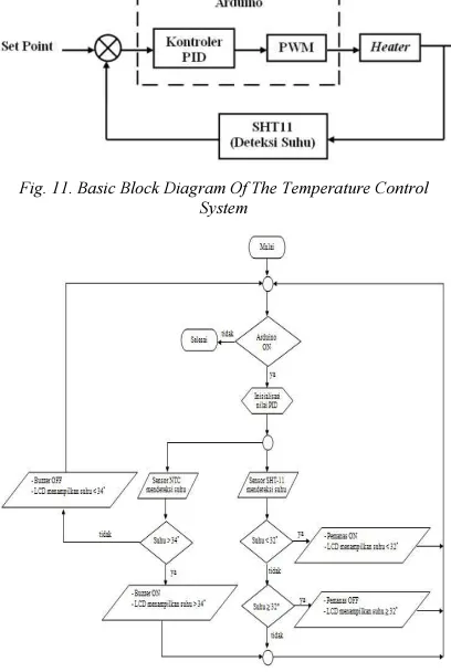
Temperature regulation is done by regulating the amount of heat generated by the heating element. Temperature magnitude is measured by the output of the temperature sensor SHT11 and used as input to the feedback controller.
[image:4.595.88.292.423.727.2]Input from sensors, is compared by a controller to input set point (desired temperature). That two variables are processed by the PID based Arduino Uno and issued in the form of PWM value. PWM value is then used as input to voltage controller block to turn on and turn off the heating element.
Fig. 11. Basic Block Diagram Of The Temperature Control System
Fig. 12. System Conditioning Flowchart
F. Software Design
In this research, the authors use the method of Proportional, Integral, and Derivative (PID) of the Arduino IDE and programming software.
Fig. 13. Arduino IDE Program
G. PID Source Code
Programming of PID in this paper is using the Arduino IDE software. The source code is done in two stages, namely the initialization parameters of PID and PID main system programming. The first step in programming is to determine the PID parameters needed. Some variables are determined such as the value of the input, the output value, the value of the set point, the value of Kp, the value of Ki, and the value of Kd. Once the initializing parameters of the PID-parameters are determined, the next step is the main program implementation.
4.
TESTING AND ANALYSISA. Testing System
Testing of the baby incubator temperature control system is divided into two parts. The first is measured at the temperature conditioner and then compared with measurements made with an analog thermometerr.
The second part is the temperature measurement of the incubator system settings to get the PID parameters (Kp, Ki, and Kd). Determining of the value of Kp, Ki, and Kd is done by Ziegler-Nichols 1st method. After obtaining the values of Kp, Ki, and Kd then it will be applied to the plant to know the response of the plant and then carried out the analysis to look at the effect of the PID system.
B. Temperature Conditioning Device Testing
( )
(
( )
)
[
3]
ln
ln
1
T
T
D
R
R
B
A
T
=
+
+
(3)
Before performing measurements on the temperature sensor NTC, firstly NTC sensor is going through the calibration process by as much as 4 times of the calibration scenarios with the room thermometer, namely 10, 20, 30, and 40 trials on 3 set point temperature, at a temperature of 7°C, 27°C, and 47°C.
C. PID Control Designing and Testing
PID control system design in this researchl is done by Ziegler-Nichols 1st method. This method gives the plant a unit-step input form. Therefore, the plant does not have the integrator so that it yield curve response of unit-step input as the shape of the S (S-shaped). This response curve will be used to find the delay time (L) and time constant (T) with the help of a tangent. From the values of L and T, we obtain later sought value Kp, Ki, and Kd with the aid of Ziegler Nichols tuning table. These variables then are applied to the plant to see the response with a PID control system.
[image:5.595.306.508.329.584.2]The first step in this design is that we provide input to the plant, which is the value of Kp = 1, Ki = 0, and Kd = 0 and obtain the response graph.
Fig. 14. Plant Output Response Graph With Kp = 1, Ki = 0, And Kd = 0
The second step is to find the value of the delay time (T) and time constant (L) with the addition of the tangent line on the graph output response of the plant. Through calculation, obtained value of L = 12 and T = 138,27 so the value of Kp = 13,827, Ki = 0,576, and Kd = 82,962.
D. TestingAnalysis
Analysis performed to further explanation is about how the qualities of each system part from the temperature sensor of the incubator to the PID control system.
E. ReadingAnalysis of Incubator Temperature
Temperature sensor reading on a device carried by the NTC sensor and read out SHT11 produces almost the same value. Temperature readings by SHT11 sensor at 23,80°C, NTC sensor at 23,47°C
and room thermometer at 24°C. The comparison result of sensor NTC, sensors SHT11 and room thermometer is about 1-3 %. When compared with existing theory, the value of the NTC sensor reading error results if the readings is still performed at a temperature range up to 200°C with an error of 0,2%. The difference between data sheet and actual temperature readings is occurred due to the lack of calibration of the device. The more number of calibrations performed at NTC sensor (infinite worth), the more accurate readings on the sensor NTC.
F. Testing Analysis of PID Control System
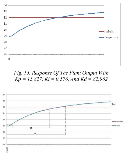
From the calculation of the Ziegler-Nichols 1st method, a score Kp = 13,827, Ki = 0,576, and Kd = 82,962. These values are then used again to control plant and temperature responses obtained as follows.
Fig. 15. Response Of The Plant Output With Kp = 13,827, Ki = 0,576, And Kd = 82,962
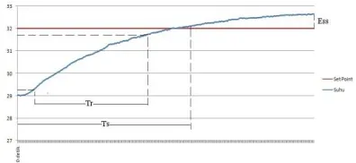
Fig. 16. Parameters Rise Time (Tr), Settling Time (Ts), And The Steady State Error (Ess) With Kp = 13,827, Ki
= 0,576, And Kd = 82,962
Using PID parameters Kp=13,827, Ki=0,576 and Kd=82,962 result rise time (Tr) 200,47 s, settling time (Ts) 306,16 s, and the steady state error (Ess) 29,16%.
[image:5.595.87.295.438.515.2]values are then used to control plant and temperature responses obtained are as follows.
Fig. 17. Parameters Rise Time (Tr), Settling Time (Ts), And The Steady State Error (Ess) With Kp = 13,827, Ki
= 0,576, And Kd = 80
In this condition, the obtained rise time, settling time and steady state error are 188,65 s, 285,67 s, and 20%.
[image:6.595.89.287.391.482.2]The second test is done with Kd=70 and fixed value of Kp and Ki. The obtained rise time, settling time and steady state error are 165,2 s, 259,19 s, and 21,875%.
Fig. 18. Parameters Rise Time(Tr), Settling Time (Ts), And The Steady State Error (Ess) With Kp = 13,827, Ki
= 0,576, And Kd = 70
5.
CONCLUSIONIn this paper, analyses and design of PID based baby incubator is presented. The design is proposed to replace the conventional on off baby incubator to convenient purpose. Based on the experimental tests, the system is performing well.
REFRENCES:
[1] Directorate General of Nutrition, Maternal and Child Health, “Management of Low Birth Weight Babies for Midwives and Nurses”, Indonesian Ministry of Health, Jakarta, 2011. [2] Bachri, Samsul, “Hybrid PID-fuzzy logic of DC
motor control,” Teknologi Makara, Vol. 8, No. 1, April 2004, pp. 25-34.
[3] Pratiwi, Dimas Putri, “Monitoring and controlling of Wifi based baby incubator,”
Bachelor Thesis, Telkom University,
Bandung, 2014.
[4] Ilyas, Jurniarni, “Training of baby incubator”, Erlangga, Jakarta, 1995.
[5] Johnson, Michael and Mohammad H. Moradi,” PID Control: New Identification and Design Methods”, Springer-Verlag, London, 2005. [6] Ogata, Katsuhiko, “Modern Control
Engineering”, 3rd Edition, Prentice-Hall, New Jersey, 1997.
[7] Rajkumar Bansal, A.Patra & Vijay Bhuria, “ Design of PID Controller for Plant Control and Comparison with Z-N PID Controller”, International Journal of Emerging Technology and Advanced Engineering (IJETAE), Vol. 2, Issue 4 of April 2012.
[8] Atmel Corporation, “Datasheet AVR ATmega328,” www.Atmel.com, 2009, accessed at 5th December 2013.
[9] _________,
http://arduino.cc/en/Main/arduinoBoardUno, accessed at 9th Desember 2013.
[10] Sensirion,“SHT1Datasheet,”
(http://www.sensirion.com/en/products/humidit y-temperature/humidity-sensor-sht10/, 2011, accessed at 12th January 2014.
[11] _________,
http://www.centralelectro.com/search.php?sear ch=sht, accessed at 26th January 2014.
![Fig. 4. Arduino Uno Module [9]](https://thumb-us.123doks.com/thumbv2/123dok_us/8911467.959511/2.595.348.462.544.627/fig-arduino-uno-module.webp)