The policV of International Computers limited Is one of continuous development and improve-ment of its products and services, and the right Is therefore reserved to alter the information contained in this document without notice. ICl makes every endeavour to ensure the accuracy of the contents of this document but does not accept lIabilitv for any error or omission. Anv equipment or software performance figures and times stated herein are those which ICl eKpecls to be achieved in normal circumstances. Where-ever practicable, ICl is willing to verify upon request the accuracy of any specific matter con-tained in this document_
With effect from 12th August 1968 the name of English Electric Computers
has been changed to
International Computers limit .. d
Technical Publication 1002 mm (R) @)International Computers Limited 1969
First Edition Januarv 1968 Second Edition October 1969
Issued bv Technical Publications Service International Computers limited
Head Office: ICl House, Putney. london SW15 Produced bV I CL Printing Services
CONTENTS
SECTION Page
l' Introduction
I-I The Basic System 1
1·2 Program 2
1-3 Hardware and Software 2
1-4 Programming Languages 2
1-5 Ability of Computer 3
1-6 Example of Usercode 3
2' Number Systems
2·1 Information Inside KDF 9 5
2- 2 Rules of Number Systems (Integers) 5
2-3 Rules of Number Systems (Fractions) 7
. 2·4 Conversion between Systems 8
2-5 Arithmetic Operations 10
2'6 Exercises 13
3' . Representation of Information
3-1 Main Store Memory of Bits 15
3'2 KDF 9 Character Code - paper tape 15
3'3 Referencing a particular digit 17
3·4 Kinds of Data 17
3-5 Number Representation 18
3-6 Fixed Point Numbers 19
3'7 Floating Point Numbers 22
3-8 Standard Floating Point 23
3·9 Number Precision 23
3'10 Examples 24
3'11 Exercises- 24
4' Breakdown of KDF 9 Word 28
6' Logical Structure
5-1 Main Store 31
5-2 Peripheral Device 32
5'3 Nesting Store 34
5-4 Arithmetic facilities 36
5-5 Q-store 36
6·6 Control Unit 37
SECTION Page
6- Programs
6-1 USERCODE - Mnemonic Code 41
6-2 Example of Program 41
6-3 Library Extraction 45
6-4 Use of Main Store 46
6-5 Usercode CompiIer 48
6-6 Layout of Information in Main Store 48
6-7 Program Heading 50
6-8 Exercises 51
7- Constant Declarations
7-1 Definition of Constants 53
7-2 Compiler Actions 53
7-3 Numeric Constants 54
7-4 Binary Constants 56
7-5 Address Constants 57
7-6 Q-store Constants 58
7-7 Half-length Constants 59
7·8 P-Constants 60
7'9 The Instruction 'SET' 62
7·10 Exercises 65
8' Operations on Q-stores
8-1 One Q-store manipulative instructions 67
8-2 PartQ-store manipulative instruction 68
8·3 Two Q-store instructions 70
8·4 Q-store 0_ 70
8·5 Example 71
8·6 Exercise 71
9- Nesting Store Manipulations
9·1 Instructions 75
9-2 Example 76
9-3 Exercises 76
10- Main Store Operations
10-1 General Prine iples 79
10-2 Direct AddreSSing 79
10'3 Indirect AddreSSing 81
10-4 Jumps on Counters 82
10-5 Modified Address with Q facility 83
10-6 Examples 84
SECTION Page
11- Basic Arithmetic Operations
11-1 Addition and Suuh'aclion 119
11-2 EXllmplcs 92
11-3 Logical Ollcrations 92
11-4 Radix Convcrsions 94
11·5 Exerciscs 98
12' Output Via OUTS
12·1 General Principlcs 101
12·2 OUT8 101
12'3 Dircctor's actions 102
12·4 Rules for Stream Numbers 102
12·5 Standard Plug Board 103
12·6 Punched Tape 103
12· 7 Examples 104
12'8 ExerCises lOS
13' Jumps.
13'1 .Jump Instructions 107
13'2 Examples 111
13'3 Exercises 111
14 introdUCtion to Library Extraction
14·1 General 113
14'2 Examples 113
14'3 Recommended format 114
14-4 Exercises 114
15- COlICept of Flowcharting.
15-1 General 117
15-2 Conventions 117
15-3 A Single Flowchart 120
is-
Programming Exercise A16·1 Example.problem 123
lS;2 Solution 124.
lS-3 Exercise 126
17- Input/Output Instructions
17-1 Basic Requirements 129
17·2 Devicc and TY)JEl Numbers 130
17-3 OUTS 130
17·4 Paper Tnpe 133
17·5 Purity and 8th Hole 135
17'S Fixed arid Variable length Dala 135
17'7 Paper Tape Instructions 1:J6
SECTION Page
17-9 Protective Interlocks and Lockouts 139
17-10 On-line Typewriter 140
17-11 High Speed Printer 14~
17-13 Exercises 145
IS- Double and Half Length
IS-I NEXT facility 149
lS-2 Half -length felch and store 150
lS'3 Q.H.N. 151
lS-4 Examples 151
lS-5 Exercises 152
19- Multiplication and Division
19-1 Multiplic ation 153
19-2 Division 156
19-3 Examples 158
19·4 Exercises 159
20- Further Arithmetic Instruction
20-1 Shift Instructions 163
20'2 Accumulative Multiplication 165
20-3 Multiple Length Division 165
20·5 Single length Floating-Point 167
20-6 Numbers other thnn pure integers 170
20-7 Examples 170
20'S Exercises 171
21' Programming Exercise B 173
22- Magnetic Tape
22-1 Magnetic Tape Units 177
22'2 Examples 190
22-3 Exerciscs 191
23- Subroutines and S. J . N . S.
23·1 Functions of a Subroutine 193
23·2 Rules for writing subroutines 193
23'3 Control of S.J.N.S. 196
23-4 Examples 199
23-5 Exercises 199
24- Advance Control
24-1 Advance Control 201
24' 2 Short Loops 203
SECTION Page
2&' Programming Exercise C 207
26' Director
26'1 Basic Functions 211
26·2 Entries to Director 212
26'3 Machinc Code Program Format 214
26·4 Typewritcr Interrupts 217
26'6 TYP(lwriter Log 219
27' US3rcode Compiler
27'1 Heading Sheet 221
27·2 Store Layout 224
28' Operating Instructions
28'1 Presentation 225
28'2 Format 225
28'3 Magnetic Tape schedulc 228
28'4 Operating Instructions 229
28'5 Restarts 229
28'6 Work tapes 229
28'7 Flexowriter 230
28'8 OUTS and OUT6 230
28'9 Paper Tape 230
28'10 OUT8 230
28'11 Timesharing and store limits 231
28'12 Time limits on programs 231.
29' . Software
29'1 NINEMASTER 233
29'2 Normal usage 233
29'3 Service Routine Library Manual 233
29·4 Exercise 233
30' IntroductiOn to Post
30'1 Principle 235
30'2 Postmaster Directives 235
30'3 Assembly Phase Messages 236
30'4 Correction Texts 237
30'5 Translation Phase Messages 240
Appendix 1 Appendix 2 Appendix 3 Appendix 4
Appendix 5 Appendix 6 Appendix 7
Appendices Answers
Review of elementary mathematics Powers of Two
Instruction Cross Reference List (with syllable counts)
Reference Tables, Failure Reports, etc., Other Peripheral Devices
Programming for TM 4 on KDF 9
Page 241 269 275 277
1- INTRODUCTION
1·1 The Basic System
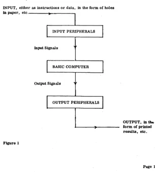
All electronic digital computers consist of two main categories of equipment:
(a) The 'black boxes' which perform all the calculations, processing of data, etc. and
(b) The' peripheral devices' via which the black boxes communicate with the outside world.
KDF 9 is such a machine.
The black boxes are the Basic Computer, and unless peripheral devices exist to feed in (input) commands and give out (output) results of calculations, etc. It Is virtually useless to man.
INPUT, either as instructions or data, in the form of holes In paper, etc. _ _ _ _ ~_---...,
Input Signals
BASIC COMPUTER
Output Signals
[image:10.435.69.385.230.580.2]OUTPUT PERIPHERALS
Figure 1
OUTPUT, In
u...
form of printed results, etc.1-1-1 Peripheral Devices. Peripheral devices for input may be such items as paper tape readers, electric typewriter (flexowriter), punched card readers, magnetic tape units, etc .• which are the media via which we com-municate with the machine.
The output peripherals are such as high-speed-line-printers. and paper tape punches.
1-2 Program
A sequence of instructions which the computer is to obey is known as a Program.
After a programmer has written a program it is prepared in a manner accep-table to one of the input peripherals. This device converts the program into input signals which are fed to the computer and stored away in the 'memory' . When all the instructions of the program have been stored away. and when certain requisites have been carried out the computer fetches the instructions, one at a time, from its memory and obeys them. Should the instructions, whilst being obeyed, require some data from outside the computer, this will be asked for and be expected to be received from one of the input peripherals. Eventually the results are passed to an appropriate output device for printing, etc.
1- 3 The Hardware and Software
The physical ironwork and electronics of the basic computer and its peripheral devices are known as the 'hardware' .
Those programs which enhance the ability of the hardware are called the , software' .
The hardware by itself is like a car without a driver. It has ability to do certain things but must be instructed (by software) what to do.
The main 'driver' of the hardware is that part of software known as the ''DIRECTOR'', which is a program that is fed into the machine at the beginning of the day, and stays there governing the functioning of the computer. This Director program will arrange for other programs to be received one at a time into the computer and for thein to be run. On some versions of KDF 9 the Director program may be controlling four programs running concurrently.
1·4 Programming Languages
The computer is designed to only understand instructions Which are in a language called 'Machine Code' (sometimes referred to as Binary Code). A program of instructions in this code is not easily written, so another language has been devised called USERCODE which is a mnemonic code, easily understood and which has a one-to-one correspondence with Machine Code.
then able to obey the instructions of the translated version.
1· 5 Abllity of the Computer
A widely held misconception about computers is that they can 'think' like a brain. This is not true. They obey instructions - admittedly much faster than man can do - but that is all. These instructions, the program, must be precise, and, if the results are to be of use, correct. Any logical error made by the programmer, generally, will not be detected by the computer. Hence a com-puter is not an cJectronic brain, it is an extremely fast obeyer of instructions.
1·6 Example of a USERCODE Program Body
This is an example of a simple Usercode program, which causes two numbers to be read in, added, and the result fed out. The reader is not expected to understand it until he has learnt, among other things, the computer's logical structure and information representation.
VO Q 0/AY27/AY27; VI Q 0/ A Y92/ A Y92; V2 Q 0/AY43/AY43;
YO; =QI; SET2; SET5; OUT; (OBTAINED USE OF READER); VI; =Q2; DUP; =CI; =C2;
V2; =Q3; SETI; SET5; OUT; (OBTAINED USE OF PUNCH); =C3; PIAQI; PARQI; (1ST NO. READ INTO Y27); JITR;
PIAQ2; PARQ2; (2ND NO. IN Y92); JITR;
Y27; Y92; +; (NOS. ADDED); ';Y43; (ANS IN Y43); POAQ3; (Y43 PUNCHED);
1; Cl; SET6; OUT; C3; SET6; OUT; ZERO; OUT; FINISH;
NUMBER B'YBTEMS
I-I lldormatiOll Inside KDF 8
Information to be understood by KDF 9 has to be in binary patterns and on occasions communication between the computer and programmer requires the octal representation of these binary patterns. The following will explain binary and octal number systems with reference to the more famlliar decimal system.
2· 2 Rules of Number System (Integers)
When counting In the decimal system, only one of the digits 0 to 9 Is needed, until it becomes necessary to specify the number "ten". We then put a 1 In the next column to the left and reset the original digit from 9 to O. So to represent "ten" we put 10, where 1 is a digit and 0 is a digit; notice that 10 is not one digit, it is a combination of two digits representing a number.
When ''nineteen'' is reached and the next number is required to be written down there is no digit left to be put Into the right hand column so 0 is placed there and "one" added to the tens column. This process continues until "one-hundred" is required when the carry goes even further to the left.
There are two essential points to notice about this famillar process:
(al There could be as many zeros as we liked to the left of the number (assuming it to be an integer) so that 0000027 is just the same as 27,
and
(b) A carry into the next most significant digit position occurs whenever the given digit reaches the value "ten".
More formally it is said that any integer number n can be represented In the decimal system by the equation:
r 0
n = ... +(dr x 10 )+ ... +(do x 10 )
where do, d1, etc. may be any of the digits 0 to 9.
Bear in mind that, for example, "sixteen" is the WORD used to represent the number, whereas 16 is the representation of that number In the decimal system. In facti 16 should be written as (1 x 101) + (6 x 100), but by convention we drop the 101 etc.
1·1·1 Assume man had used a number system based on eight digits only (0
to
7). Counting would be up to 7 and then the 'carry one' performed. This would mean that to represent "eight" 10 would have to be written. Such a system based on the digits 0 to 7 is called the Octal System. The octal l_ Is thus the same value as the decimal 8.Below a few decimal and octal numbers are listed for comparison.
Decimal Octal
6 6
7 7
8 10
14 16
15 17
16 20
19 23
20 24
Formally it is said that the number n can be represented in octal by:
r 0
n = ...•.•.••• +(dr X8 )+ ... +(doX8)
where the d's may be any of the digits 0 to 7.
2·2·2 The base in the decimal system is "ten" and in octal "eight". This base is called the RADIX of the system. In order to avoid confusion between various systems the radix is written as a suffix in parenthesis after the number unless it is abundantly clear which system is being used. Hence "fourteen" would be 14(10) or 16(8)'
It is possible to have a number system with a radix of any number greater than 1 provided symbols are devised to represent digits greater than 9.
2·2·3 The Binary System is a number system with the Radix 2, the permissible digits being 0 and 1.
The corresponding Binary equivalents of the decimal numbers 0 to 10 are:
Decimal Binary
0 0
1 1
2 10
3 11
4 100
5 101
6 110
7 111
8 1000
9 1001
10 1010
Formally it can be said that a binary number such as 1101001 represents:
6 5 4 3 2 1 0
(1 x 2 )+(1 x 2 )+(0 X 2 )+(1 x 2 )+(0 X 2 )+(0 X 2 )+(1 X 2 )
2·3 Rules for Number Systems (Fractions)
Extension of thc above section to cover fractions only requires the indices of the Hadix to be continued to negative values.
The dccimal number 26' 905 in full should be written as
1
°
-1 -2 -3(2 x 10 )+(6 x 10 )+(9 A 10 )+(0 X 10 )+(5 x 10 ).
Conventionally the 10' s arc dropped and to indicate where the indices of the radix changc from positive to ncgative a point (in this system called the decimal point) is inserted. Th(!re could be as many zeros as desired to the right of the fraction so that the above number is also 0026·905000; the same rule applies in othcr systcms with radices other than "ten".
2·3·1 In the octal system 15·\8) in full is
1
°
-1(1 x 8 )+(5 x 8 )f(4 x 8 ) which is (1 x 8)+(5 x 1)+(4 x
A)
or 8 + 5 +
1
N.B. The point in 15'4(8) is called the octal point.
2·3·2 Similarly in the binary system 1011'01(2) in MI is
(1 x 23)+(0 x 22)+(1 x 21)+(1 x 2°)+(0 x 2- 1)+(1 x 2-2)
which is
(1 x 8)+(0 x 4)+(1 x 2)+(1 x 1)+(0 x 1)+(1 x
!)
or 8 + 0 + 2 + 1 + ° + ~
or
n·
25 (10)N.B. The point in 1011'01(2) is called the binary point.
2·3·3 In decimal, 15·63472 is regarded as representing a number to 5 decimal places, which are lUlderstood to be 5 decimal fractional places. In octal and binary the expressions are octal fractional places and binary fractional places respectively.
2.3·4 It shoUld be exphasisL'<i that when we call 25, "twenty five", we are justified in doing so because in everyday language it is lUlderstood that the decimal system is being used. However, should be wish to talk of 31(8) we must say, "three, one, octal", or "the octal representation of twenty five".
In the same way in binary, 101(2) should be referred to as "one. oh, one. binary". or "the binary representation of five".
The reader should acquire the good habit of referring to numbers correctly; if
he doesn't he will find himself making such 'mistakes as wriling 1101 for "eleven hundred and one" and then think of it as "thirteen" because he can see only l' s and 0' s and immediately treat it as a binary number. '
2·4 CODversiem between Systems
Conversion of a number from its representation in one system to another has to
be performed in two stages: first the integer part is converted by one process and then the fraction part by another. The two results are then written down with the point inserted. The reason for this dual process is that integers have positive radix indices whereas those for fractions are negative.
N . B. The reader is asked to bear in mind that this process is used by man when converting on paper; in the computer the method is somewhat different. Confusion between the two methods and their particular application could unnecessarily increase the length of the program.
The Rules for Cemversiem (em paper)
1. Integers
(8) From Decimal to another system. Divide the decimal number by the radix of the other system and keep a record of the remainder; divide the quotient by the same radix recording the remainder and repeat this step until the quotient is O.
The resulting remainders in reverse order are the digits of the number in the new system from left to right.
Example: to convert 8632(10) to octal.
8 l8632 8
1..
1079 r. 0 81
134 r. 7 81
16 r 6 81
2 r. 0 -0 r. 2Hence 8632(10) is equivalent to 20670(8)
(b) From another system to Decimal. Multiply the most significant digit by the radix from which the conversion is taking place;' add the result to the next digit of the original number (0 is a digit) and again mulUplyby the liame radix; continued oruy to the stage when the current result is added to the digit in the ' units column of the original.
Example: to convert :1645(8) to decimal.
3 6 4 5
~ + 24 + 240 +1952
21 ao 244 1957
x 8 ~
2'10 1952
Hence 3645(8) is equivalent to 1957(10)
2. Fractions
(a) From Decimal to another system. Multiply the fraction by the radix of the other system and keep a record of the resulting integral part; multiply the resulting fractional part by the radix and repeat until the fraction becomes zero or until sufficient precision is obtained. The resulting integral parts are the digits of the number in the ncw system from left to right; the point must then be inscrted to the left of the number.
Example: to convert 0068:159:175(10) tooetal.
0068:159:175 8 (0) 0546875000 _ _ 8 (4)' :175000
_8 (:1)0000
lIence 0 068:J59:J75 (10) is equivalent to 0 04:J (8)
(b) From another system to Decimal. Divide the least significant'digit by the radiX, obtaining a fraction, insert the next digit of the original in front of this resulting fraction and again divide; continue until all digits of the original (including all zeros) have been brought down and divided.,
Example: to convert 00273(8) to Decimal.
8
/
:J·OOOO ·3758
/
7·375 ·9218758
/
2'921875 • 3652a<l:l75Il / O· :1652:14:175 '0451l54296875
Hence' 027:1(8) is equivalent to 0045654296875 (10)
N. B. The reader is not expected to learn these rules by heart.
2·4'2 Octal to Binary and vice versa. The group of three binary digits 111 represents "seven"; if a 1 is now added the group becomes 000 and a 1 appears to the left.
Since the largest possible value for the group of three digits is seven, the group can be looked upon as having a Radix of eight. There then must be some relationship between these groups of three binary digits and the octal number system.
By inspecting the follOWing examples it will be seen that every octal DIGIT can be written down directly as its equivalent group of three binary digits. It must be emphasised that the full group of three must appear so that '1(8) is not· 001(2) and NOT '1(2)'
However, more significant integer zeros and least significant fraction zeros may be omitted, e.g., '2(8) = '010(2) = -01(2)
Octal
5(8) 27
Binary
101(2)
010 111
·010 011
10111
·010011 ·23
12·36 001010 -011 110 = 1010'01111
In the last example, had it been required to convert 1010,01111(2) to octal, the necessary 0 I s would have had to be inserted in order to complete the groups of
three before writing down the octal equivalent:
viz., 1010·01111 = 1 010 • 011 11
= 001010 • 011 110: 12'36(8)
Another point to remember is that when converting from binary to octal, the grouping of threes must proceed from the binary point in either direction.
2' 5 Arithmetic Operations
The arithmetic operations used in decimal notation apply equally in the other number systems provided it is remembered that the digits available for use are restricted to one less than the radix being used, and that the multiplication tables are ·different.
Examples of the tables in octal are
x 3 x 6(8) x 5(8)
x 10(8) (8) 14 44(8) 43(8) 100(8) (8)
There is no neL>d to learn the tables for the different systems; merely use the normal tables and convert the partial answer of each operation performed. So that, to multiply 35(8) by 4 (8) the procedure is:
3 5
6
4 4 x 5 ~ 20 20 (10) ~ 24 (8)
4 put down 4 and carry 2
4 x 3 = 12
12 (10) ~ 1\8)
14(8) + the 2(8) carried ~ 16(8)
put down 6 and carry 1
Answer 1
1 6 4 (8)
no more working so put down the 1 (8) carried
This is rather a tedious process, probably the reader would rather convert both the multiplicands to decimal, obtain the product and then convert the answer back. In practice programmers seldom find the need to perform this operation, or in fact any of those in the next section but nevertheless he should know what to do (-or better-where to look) should the need arise.
2·5·1 Examples of the four arithmetic rules are now given, using the same equivalent numbcr in each group of three.
Decimal
Addition 22
(a) +21
4:1
(b) 23·5
22·25 +21·5 67·25 Octal 26 +25 53 27·4 26·2 ~ 103·2 Binary 10110 +10101 101011 10111· 1 10110·01 +10101·1 1000011·01
Subtraction (a) (b) Multiplication (a) (b) 24 -20 4 34·0 -15-5 18'5 Decimal 3 x4 12 25'50 x 12·25 25500 00 5100 00 510 00 127 50 31237 50 = 312- :1750
30 -24 4 42'0 -17-4 22-4 Octal 3 x4 14 31-4 x 14'2 3140 0 1460 0 63 0 4703
=470'3
Division (This 1s nasty at the best of times _)
Decimal
(a)
Page 12
O· 5454 ______ etc_
11/
6'050 44" 60 55 50 44 6 Binary
0-100010: _____ etc_ 1011/ 110·0
101 1 10 00 100 000 1000 0000 lliOO"o
1011 etc_
11000 -10100 100 100001·0 - 1110-1 10010-1 Binary 11 x 100 1100
11001'1 x 1100'01 110011000 00 11001100 00 1100 11 1001110000 11
= 100111000-011
Octal
0·4272. __ ••• etc_ 13/ 6-0
2· 6 Exercises
1. What is the formal representation of:
(i) 157 (10) (i1) 29 5 • (10)
(iii) 157 (8)
(iv) 35-4(8)
(v) 101(2)
(vi) 1101-01(2)
2. How would you represent "forty-five" in:
(i) decimal; (ii) octal; (iii) binary;
3. How would you represent "sixteen and a half" in:
(i) decimal; (ii) octal; (iii) binary;
4. Write down the binary equivalent of:
(i) 634- 23 (8)
(iii) 100· 001 (8)
6_ Write down the octal equivalent of:
(i) 101101>101(2)
(ii) 1101-1101 (2)
(iii) I-I (2)
. 6. Perform the following:
(i) 276 (8) + 167(8) + 32(8)
(iv) 521· 63 (8) - 43· 67 (8)
7. Perform the following operations on the binary numbers given. (Hint; in some oases, when the binary number has many digits it may save time to convert to octal - calculate in octal - then convert back to binary.)
(i) 1011-1101 + 11·101 + 1·0001 (U) 1010111000011·00101 - 1001001·00010
(iii) 1011·1101 x 11·101
(iv) 10101·1 + 11·01 correct to 2 binary places.
3· REPRESENTATION OF INFORMATION
3·1 Information Storage
To hold information, each storage location in the main "memory" is equipped with 48 miniature mab'l1ctic cores and depending on the direction of magnetisation, the computer will understand each core to represent either 0 or 1. Thus it is possihle to hold a pattern of 48 binary digits, called' bits', at each address. This pattern is called a 'word' .
For Bimplicity the contents of a 'word' can be represented on paper by sixteen octal (ligits, one for each group of three binary digits. If for a moment we assume that mab'l1ctisation of the cores ;mtielockwise means 0 and clockwise me;ms 1, and assuming that each word has only 12 instead of 48 bits, then the configuration:
"",_r-0 "",_r-0 "",_r-0
...
0 0 0'"
,...,~ 0 0 0....
3·2 KDF 9 Character Code
o
(j(j' is understood to be: ~ (2) which may be written as:2
(8)
It is now appropriate to discuss the KDF 9 Character Code, which is employed for the typewriter :mel 8 hole paper tape. Most readers will know that the Morse Code (md the teleprinter eode represent characters such as digits, letters of the alphabet :Uld punctuation marks by dots and dashes from a buzzer, or holes :md the absence of. holes in paper tape. The KDF 9 Code is very similar.
A character is formed from 6 binary digits (bits), but it is more convenient to look upon it as being formed from two octal digits. The number of different patterns that may be constructed in this way from six bits is 64, viz., 0 to 63 inclusive. Since provision is made in the KDF 9 Charactcr Codc for a generous selection of punctuation marks and other symbols, :md further since both capital :md small letters are to be included, there are more than 64 items to be represented. This means that many patterns in the code must be used twice over. To distinb'Uish between the two possible me:mings of such a pattern,
'Case Shift' and 'Case Normal' characters arc employed. A pattern is interpreted as being a character in case shift if the last' case' character sensed was Case Shift, and in case normal if the last' case' character was Case Normal. Note that those patterns with only one meaning have that meaning in case shift or case normal.
KDF 9 Character Code
Typewriter and 8-hole Paper
Tape Version Symbol Octal Value Function Octal Value Normal Shifted
00 Space 40
01 41 A a
02 CR-LF 42 B b
03 43 C c
04 Tab 44 D d
05 45 E e
06 Case Shift 46 F f
07 Case Normal 47 G g
10 50 H h
11 51 I
12 52 J j
13 53 K k
14 54 L I
15 55 M m
16 56 N n
57 0 0
Symbol 60 P P
Normal Shifted 61 Q q
17
/
62 R r20 0 63 S s
21 1 64 T
22 2 65 U u
23 3 < 66 V v
24 4 > 67 W w
25 5 70 X x
26 6 x 71 y Y
27 7 of 72 Z z
30 8 73
31 9 74
32 75
33 I. £ 76
34 77
35 +
36
*
37
3- 2-1 Explanation of Code. The above code is used in connection with paper tape. A sl ightly modified version applies for the high speed line printer. Items left hlank such as 0 1(8)' 0:' (8) arc to be ignored.
Clt-I.F is the conventional short form of 'carringe return, line fc"d' i. c., causing the follOWing character to be printed at the
b"ginning of the next line.
Tab is the same as 'tabulate' on a typewriter.
20 Shifted Is USed mainly in connection with' Algol' and refers to exponen-(8) tiation.
:12
(fl) To cause a character to be underlined it is only necessary to precerle the character with :12 (8) .
The carriage of the flexowriter docs not move after underline is typed.
:1:1 (8)Normal Is a suffix 10 below the line, and is on one character key.
7[) (8) Is the symbol called' End Message' .
It must be emphasised that 20(8) to :11(8) inclusive (in case normal) only refer to the character form of the digits. If an address is to contain "thirty-eight", then feeding in 2:1(8) followed by :10(8) would not be sufficient. This would only have stored the character code of the digits :I and 8. The method of converting
2:1(R) , :10(8) into the NUMBEH "thirty-eight" will be dealt with under 'Radix Convertion t •
3 - 3 Reference to a particular digit in a KDF 9 word
The 48 binary digits in a KDF <;l word are numbered for reference purposes 00-047, with 00 the most Significant (Le., the extreme left) digit.
The abbreviation Op is often used and interpreted to mean, according to con-text, either:
(i) The p th digit of a word, or
(ii) A word containing a 1 in the pth position and 0 I S elsewhere. Even though only the digits 00-047 exist, there is no reason why we should not give p a value outside the range 0-47 and talk of, say, 049 or even D (-4), but of course these digits will not exist in the word.
3-4 Data
In Chapter 1 we saw that the words of the computer may contain either instructions to be performed or data relevant to the problem.
Data may be of two kinds:
(i) Numbers which the computer works upon. and
(li) Characters of the Character Code.
It has already been shown how characters are stored; we shall now consider the storage of NUMBERS.
3' 5 Number ReprssElDtatim
. Before we consider the representation of numbers in the computer we need to be equipped with two new concepts of numbers.
<a) Any positive number may be represented by a fraction multiplied by an integral power of nn integer.
e.g .•
+26·3 (10)
+0, 014(10)
26'3 100
26'3 32
x
x 2 5
·014 -6
. 015625 x 2 (see Appendix 3 for powers of 2)
(b) Any fraction may be represented by the integer 0 or -I, plus a positive fraction.
e.g .• +'47(10)
-·47 (10)
o
+ ·47-1 + ·53
By combining these two concepts we can represent any positive or negative number 'x' by the equation:
e.g. ,
Page 18
x (-s+f) x RP where s is 0 for poSitive numbers, and
+26'3(10)
+26'3(10)
1 for negative numbers; f is nny positive fraction; p is a signed integer; R is a positive integer.
+0·47
(10) Note that the representation
of these two numbC!rs docs not only vary in 's' but necessarily also in • f' because: -1 +
:!I
-0' 5:11
3' 5·1 Numbers in KDF 9. KO fo' 0 uses this equation to represent numbers, .and siOl'e the computel' works in binary the value of R is always 2, so that the
equation becomes:
Provided the values of s, f and p, arc recorded, the value of x is uniquely specified.
There arc two ways of recording s, f and p:
(a) In a system called' Fixed Point' - where: s is held in ~O, ~Uld
f in D I-D4 7 in binary (the computer underst:Ulds that the point is between DO and DI),
The programmer has to remcmber the valuc of each of the p' s for every word containing a fixed point number,
(h) In a system callcd • Floating Point· - whcrc: s Is hcld in DO,
I" in DO-D47 in binary (thc computer understand that the point is bclween 08 and D9), and
p Is held in D I-D8 in a kind of binary,
Since, in both systems, • s' reprcsents either a positive or negative number by 0 or 1 respectively, and is held in DO, we call DO the Sign Digit.
To differentiate betwecn fixed and Floating-Point Number instructions the latter are followed by thc lellcr F,
3' 6 Fixed Point Numbers
Thc computer understands the layout of a fix cd point numbcr to be:
DO Dl D2 D:I D4 D5 . . . D46 D47
~.
-vc +vc
s
Programmer's Notebook
± ve p
If's, f and pare reeorded as sho'Ml above we say that' the number x is held in the word to p integral places'. This means that the true value of x is obtained when the point is taken from between DO and Dl and placed just after Dp; this implies that the digits D1 to Dp are binary integral plaees, (the Sign Digit, DO is not included).
In fact the programmer always (in fixed point numbers) considers the point to be just after Dp.
Examples; If the word contains;
DO D1 D2 D3 D4 D5 D6 D7 DB ... D47
o
o o
o
o
1o o
o
o
and the programmer considers it is holding x to 5 integral places. (i. e. , p~5 and the binary point is just after D5) then the true value of x is 00001. 0000 ... =\2)'
If he considers that the number of integral places is :!, i. e., the binary point is just after D3, then x is 000.01000 ...
=. 01 (2)'
Again, if he considers it is -4 integral places, (i. e. , the point is just after the imaginary D (-4» then x is '000000001 = 2-9 .
Making p very large (and hence f very small) for a particular value of x may result in some of the least significant digits of f being too far to the right as to be held in DI-D4 7.
Similarly making p too small will result in making f so large that it ceases to be a pure fraction, this is not permissible. It is therefore necessary to ensure that the programmer knows the limits that p can taken for any x.
The equations: x < 2P for positive x
Ixl 2P for negative x (where Ixl means the value of x without the - sign)
will give the best value of p if the algebraieally minimum is seleeted.
e. g., (I) the be3t (i. e., minimum) value of p for 28' 9 (10) is 5 because
2fl'9(10) is less than 2" (N.B. 24 " 16; 25 ,- :12; 26 c. (4)
(ii) the best value of p for -(j4 is 6 because
6
64 is less thM or equal to 2
(iii) ,Uld for +0' 26 it is -I because
-I -2 -I
0·26 is less th,Ul 2 (N.B. 2 '2,,; 2 '5)
If the value of p obtained this way is used, maximum precision will be obtained
(i. e., the smallest possible number of least sib'Ilifieant bits arc lost off the right h,Uld end) .
A larger value of p eould be used (but not smaller) if it were certain that no required digits would be lost off the right hMd end.
Regarding integers, where there arc never My bits to the right of the point, there is no reason at all why p should not be 47; in fact by making it 47, extremely large integel's eM be stored. It is left to the reader to satisfy himself that the largest positive integer possible under these eireumstMceS Is 247 -I, ,Uld the largest negative number is _2 47 .
When considering negative numbers 'Ul interesting point emerges. We know that the computer reqUires (+x)+(-x) to equal zero. That this is the case (using the s, f Md P equation) is shown as follows where x ~ • 05 (10)
+
·05 -1
+0,0" (-0+~)2
(10) v
o
'45 -1 (-I + -:[;) 2
(It is essen tial, of course, that the p for both the numbe rs to be added be the same) .
How C:Ul we quil'kly say what the contents of a word are, haVing been give the contents of a word holding a number of opposite sign?
Consider: +12(10) held to 4 integral places in a 6 bit word, added to
-12(10) held to 4 integral places in a 6 hit word.
DO D1 02 0:1 04 D5
0 1 0 0 0 +12
+ 0 0 0 0 -12
,0 0 0 0 0 0
,
1
There is no room in the 6 hit word to hold the 'extra' bit. so it is lost. which is exactly what we want. making the sum in the 6 bit word equal to zero. The reader is asked to verify for himself the following rule: to change the sign of the contents of a word. merely change all the I' s into 0' s and vice versa starting at the most significant (left hand) end UP TO BUT NOT INCLUDING the least significant 1 bit.
Summary of Fixed Point.
(a) The computer considers a binary point to exist between 00 and 01, with 00 = -1 or 0, and Dl to 047 as a positive binary fraction.
(b) The programmer may consider the point to be anywhere, say after Op, when he says the number is held to p integral places.
(c) For maximum precision p should have the algebraically smallest possible value.
(d) When working with pure integers p should be 47.
(e) p may be any value. even outside the range 1 to 47. in which case the extra
o
poSitions are assumed to exist.3· 7 Floating Point Numbers
The computer understands the layout of a floating point number to be:
~ • .,.;0;;,.1:...-..;;0;;.,..2 ... _._._0_7 _O_B....J~r
-ve -:Jve •
D10 D47 047 ...
+ve
S p (binary point)
In floating point we can not talk about "Integral places". the point is ALWAYS between OB and 09. The Similarity between 00 and 01-047 in fixed point, and 00 and 09-047 in floating point will be immediately obvious.
The difficulty arises when tring. in 01-0B. to represent p which may be positive or negative. From our previous discussion on the representation of numbers we saw that a sign digit is required. Unfortunately DO has already been used as the
sign digit for x. The problem is OVl'rcome by:
(i) III to UK bclllil considl'l'ed as a positive binary integl'l' with thl' point aftl'l' Uti, and
(Ii) wro bl'inll represenled by a I bit in 01 with 0' sin 1>2 to OIL
This means thal Dl lo Oil l'ontains 128(10) for p O. Any val'iation of p is added to 01' sUbtracted from this value. So tfmt, for example, p 1 lIives 10000001, aiICI p -I J.l'iv(.'s 01l1l11l.
I';xamph.·s of noaling point:
• 1 (jo 5 (J 0) where the ('OmpUll'r has bl.en told that p
00: 0
7 is relll'esl'll ted by:
01-D8 0!J-047
12H17· 1:15(10) 10000111(2) 00100001000 .. "(2)
-1(10) whcre the (·omputer underst:ul(ls p 0 is represl'Illed by:
00, 1
01-08 128tO 128(10) 10000000(2) 09-0470 allO's
Because p is indeterminale for x O. zero is represented in the computer by 00-047 bcing all 0' s, i.e., exactly as wlUt fixed point wro.
3° 8 Standard Floating Point
To simplify floating point operalions, Ute maehinc expects to find all nonling numbers in a standard form. (There is one exception, which is the instruction which converts non-st:mdard noaling numbers to standard form.)
The standard form is arranged 50 that every number is expressed as precisely as possible, which implies that p and f are chosen so that p takes the algebraically minimum possible vnlue.
3° 9 Numbers Generally
Whl'n the point in any binnry numbel' puttern is moved m places to the len the effect is to divide the number by 2m • similarly moving it to the right multiplies It by 2m.
In fixed point we have f represented by 47 bits so the precision to which we can hold :my fixed point number is 1 in 247 (i.e., 1 in about 104Xl014).
:19
In noating point f has only :19 bits and the pl'l.'CIsion is 1 in 2 (i. c., 1 in aboul 50 5Xl011).
the programmer and secondly whereas the largest integer (p-4 7). that can be held fixed point is
247 (i.e .. l'4xI014) in floating point p can be as large as 127 giving the largest integer as 2127 (Ll! .• I· 7Xl0 38 ).
3·10 Examples Character Code
1. A word containing 0755066207:l741(8)' when transferred to the typewriter causes
Mr. A.
to be typed.
2. If 4WAN. u u is typed into a word it would eventually contain
2400524156370000(8)'
(The manuscript way to indicate a space is by u ).
Fixed Point Numbers
1. The contents of a 12 bit word in octal when x is 111·01001 2 held to 5
integral places is ( )
0722(8)'
As the point can be imaginpd to be after D5 then the contents of the word arc 000111 010010. which when grouped into threes and expressed in octal is 0722. We do not show the octal point because the point is not contained in the word.
2. The least number of integral places to which -0' 124 (10) can be held in a word is -3.
-3 -3
(-0'124) = 0'124.;2 (N.B.2 = 0'125)
Floating Point Numbers
1. 7.25(10) in floating point with p = 6 is held as
o
10000110 00011101000 ... .2. 7,25(10) in STANDARD floating point is held as
o
10000011 111010000 ... .3. -7'25(10) in STANDARD floating point is held as
1 10000011 000110000 ... .
3·11 Exercises
1. If the following sets of characters are read into a KDF 9 word. show the contents of the word in octal. Case normal is assumed.
(a) ABC D 3 4 ;
(b) END uR U N u
(c) [1' Q"!~
2. If a KDF 9 word holding the following octal patterns is typed out, show the characters typed in the correct format.
(a) 06 33 07 21 00 31 06 63
(b) 07 02 41 42 06 02 41 42
~) 07 32 56 32 57 00 75 00
(Spaces are to be indicated byu)
3. What is the largest positive integer which can be held fixed point in a word of 95 bits? Answer need not be expressed in decimal.
4. Convert the following decimal numbers to the octal pattern which represents the contents of a 12 bit word, holding them fixed point to the specified number of integral places.
Number(10) Integral Places (10)
(a) 16 11
(b) -16 4
(c) -0'575 0
(d) 31·5 5
(e) -0·09375 -3
(f) 1865 as an integer
(g) 0·0001 with maximum precision
5. Write out in full the contents of a KDF 9 word, ending on the right with a string of dots to represent continuation of zeros if necessary, when the word contains the following decimal numbers in STANDARD FLOATING POINT. (Hint: compare with question 4) .
(a) 16 (d) 31'5
(b) -16 (e) 0
(e) -0'575 (f) -0-09375
'tI
i
~
THE
KDF 9
wom
~ rr~Y
HAS BE USED
48 AS
BITS
APPLICATIONS OF THE imP 9 WORD
Eight 6-Bit Alpha-Numeric Characters
One 48-Bit Fixed-Point Number
Two 24-Bit (Half length) Fixed-Point Numbers
Half of a 96-Bit (Double Length) Fixed-Point Number
_tt_
One 48-Bit Floating-Point Number
Two 24-Bit (Half length) floatingPoint Numbers
-Half of a 96 - Bit (Double length) floating-Point Number
-"-Three 16-Bit (Fixed point) Integers
Six 8- Bit Instruction Syllables
[<~)r
47 Bits (f)LSign
I
~
23 Bits (f) I(S)I
23 Bits (f) - . - - ]Sign Upper Half (U) L Sign Lowe!" Half (L)
I~
47 BitsSign
[0
I
47 B i t s - - ---~-l- _ . - ~
a-Bit 39-Bit
I (S)I (P) (Fraction) ..
~Sign
IS-Bit (Fraction) IS-Bit (Fraction)
(L') (L)
39- Bit (Fraction)
39- Bit (Fraction)
16 Bits 16 Bits 16
~-
]4' THE BREAKDOWN OF THE KDF 9 WORD
4·1
We arc now in a position to understand the various ways that the KDF 9 word may be used.
(a) Characters Each word has 48 bits and since each character requires 2 octal digits (i.e.,. 6 bits) for its representation each word may be used to hold 8.characters of the character code. The reader will often hear the expressions
'left or right justified', which means that, if only, say, 3 characters are in a word then they are placed to either the extreme left or right of that word respectively, with the other 5 characters as spaces (Octal 00).
(b) Single-Length Fixed Point Number A fixed point number of 48 bits as explained in Section 3, may be held in one word.
(0) 2-Half-Length Fixed Point Numbers Sometimes the problem in hand only rcquires fixed point numbers where If I can easily be held in 23 bits or less. Thus If' plus 00, making 24 bits, may be held in 00-023; a similar half length number may bc hcld in 024-047. Note.that integers are stored to 23 integral placcs for both the half length numbers.
(d) Oouble-Len;th Fixed Potnt Number When If I requires more than 47 bits, two 48 bit words are used to hold one fixed point number. The sign Oigit is in 00 of the more significant word. 00 of the 2nd word is ALWAYS 0 and is ignored. If' is considcred to be stored in 01-047 of word 1 and continued in 01-047 of word 2, so that a pure integer is held to 94 integral places.
(e) Single-Length Floattng Potnt Number A floating point number as explained in Section :I may be held in onc word.
(f) 2-Half-Length Floating Potnt Numbers As in item (c), above, two floating point numbers may bc hcld in onc word. The most significant half word contains 's' in 00 and 'p' in 01-08 as for a full length number; If I is contained in 09-023. The least significant half word is laid out In exactly the same manner in 024-047. The values which 'p' can assume are the same as in single length.
(g) Oouble-Length Floattng Point Number As in item (d), above, two words may be used to hold one floating point number. The sign digit is 00 of word 1. 00 of the 2nd word is ALWAYS 0 and is ignored. 'p' is held in 01-08 of word l. For engineering purposes p minus 39 is in 01-08 of word 2. If I is considered to be started in 09-047 of word 1 and continued in 09-047 of word 2. If p is less than :19, word 2 is made into all O'S.
(h) 3-Thlrd Length Integers For spl!cial purposes, which will be explained when we deal with Q-stores. it is necessry for a 48 bit word to be broken down into three IS-bit unsigned integers.
(I) Instructions Every instruction· in KDF 9 is contained in a group of 8, 16 and 24 bits. In this context 8 bits are called a syllable, so that an instruc-tion takes the length of I, 2 or 3 syllables.
In general, instructions take the following number of
syllables:-Arithmetic operations 1 syllable.
Shifts, indirect fetches and stores 2 syllables. Jumps, direct fetches and stores 3 syllables.
The number of syllables for any particular instruction will be found in Appendix 4.
The bits of a syllable are grouped like this:
00 0 0 0 0 0 0 B1B2 B3B4B5 B6B7B8
When the computer has executed an instrUction, it looks at the next two bits in the store.and finds B1 and B2 of the first syllable of the next instruction.
If they are 00 an instruction of 1 syllable is understood,
01 2 syllables "
10 or 11 " 3 syllables
For example, the instruction
II +j"
Is one syllable and stored as
00 101 110.
"
-;"is one syllable and stored
as
00 011 110.The computer senses the 00 and knows it need not look any further than this syllable for the complete instruction. The instruction "~M "is two
syllables and stored as Q .
01 000 000 kkkk qqqq
where the k's and q's are the binary of K and Q.
Any instruction of 2 or 3 syllables may overlap from one word into the next, as for example, if five syllables of a word are already filled and the next instruction has 2 syllables then one of these will go into the already partly filled word and the second into the first syllable of the next word.
This code, which the computer uses for instructions is called KDF 9 MACHINE (or Binary) CODE and is obtained from the programmer's USERCODE
instructions via the COMPILER program. Since this book only aims at teach-ing the USERCODE the binary form of instructions will not be explained further. What has been said is sufficient for the programmer's needs.
LOGICAL STRUCTURE
5'1 Main Store
The KDF 9 computer is centred around the main store, which is arranged in modules or blocks of 4096 words, each word containing 48 bits. Up to eight modules may be fitted to the machine, so that the maximum capacity .if main store is 32768 words. As mentioned earlier, eaeh bit is in fact a miniature magnetic core. Thin wires pass through these cores for purposcs to be ex-plained later.
As far as the programmer is concerned, only the sending of NEW information to a main store word will change its contents. Mere 'reading' of the word docs not destroy it. However, from an engineering pOint of view this is not strictly true; reading a word clears it and immediately replaces it.
Imagine four cores, magnetiscd, that is, holding information, and with wires passing through thcm as shown.
Pulse.
If a pulse is sent through the main wire, this will cause an the cores to become magnetised (in effect) in the direction of the pulse thus clearing the information stored. As magnetic changes only take place in the cores holding 'oncs' current is induced to flow in the sense wires as shown. It is by detecting these currents that the computer knows what each core held originally, i.e., it has 'read' the word.
The principle of reading data from and writing data into main store as follows.
The computer fetches a copy of the word into a 'transit camp' called the Fetch Buffer, by perforating six operations:
(a) The pulse is sent through the main wire.
(b) a current is induced in the sense wires.
(0) these are sent to the main store buffer, via a gate G which is closed.
(d) a copy of the word is sent to the fetch buffer from the main store buffer. and the word is pulsed back into the main store from the main store buffer.
We are then left with the original word still in the main store and a copy in the fetch buffer.
To store a word from the store buffer into the main store, the five steps above are repeated but with the following variations.
(a) Gate G is not closed so that thc buffer is not affected by the steps (a), (b) and (cl.
(b) In step (d) instead of a transfer from buffer to fetch buffer there is a transfer from the store buffer into the main store buffer.
MAIN STORE
PULSE __ ~ __ ~ __
~~e-~~--G
For those interested, it takes 6 microsecs, to perform the Mainstore-Main-store Buffer cycle, and 10 microsecs. to complete a fetch instruction.
5'1·1 The words in the main store are numbered from 0 onwards. For an installation of maximum size, the words would be numbered 0 to 32767. In the sequel the reader will see that other address notations are also used.
5' 2 Peripheral Devices
Information may be transferred into the KDF 9 system and results obtained from the system by means of a variety of input/output devices connected to the main store via sixteen peripheral buffers. Although up to four devices may be connected to each of nine of these buffers and one device to each of the other seven, a buffer can only control one of these devices at a particular instant.
Once a transfer of information to or from main store is initiated, the buffer can see it through to completion, while the main computer can continue with different work. The peripheral devices may include one or more of each of the following.
(a) Paper tape readers, reading characters punched in paper tape in 5-. 7-, or 8-hole code, at a speed of 1,000 characters per second.
(b) Paper tape punches, perforating 8-hole paper tape at a speed of 110 characters per second. These punches can be modified to punch 5-hole tape.
(c) Magnetic tape units capable of transferring information either to or from the computer at a rate of 40,000 characters per second. (These are the 1081 units)
(d) Similar units transferring 77,900 characters per second. (These are the 1085 units)
(e) Punched card readers capable of reading 80 column cards at 600 cards per minute.
(f) Card punches, punching cards at 300 cards per minute.
(g) A Magnetic drum capable of holding 40,000 KDF 9 words and transferring information to or from the computer at a rate of 5 x
11/
characters. per second.(h) Four Disc File units, each capable of holding 16 discs, which contain up to 4 x lei' words/unit each. The two exchange rates are: 4· 8 x 104 and
9' 6 x 10⁴ characters per second.
(1) A graph plotter allowing maximum plot size of 29~" wide on a continuous roll 120 feet long.
(j) High Speed Line Printers, capable of printing lines of up to 160 characters at 1000 lines per minute.
(k) An electric typewriter operating at 10 characters per second. Only one of these may be fitted, which, among other things provides a complete operating log.
Up to sixteen of the peripheral devices may operate at anyone time Protective Interlocks inside the machine ensure that no two input/output operations can proceed together if they refer to a common area of main store or to a common device. This precaution prevents the occurrence of effects detrimental to the program.
In a similar manner computation may proceed while an input/output operation Is in progress, the system of protective interlocks again preventing any possibility of interference between the two processes. Thus no information may be processed inside the machine until the transfer bringing that information into the machine from some input device has been completed.
To assist in the control of peripheral devices a one-bit register, called the 'Test Register', is used enabling the program to interrogate the various devices as to their current state. The necessary information is transferred to the test register from the buffer unit of the device concerned.
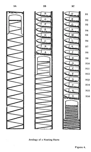
5·3 The Nesting Store
The nesting store of the KDF 9 can hold up to sixteen 48-bit words. The modc of operation of the ncsting store is completely different from that of thc main store, since the storage of words is organised in a way analogous to that used for bullets in the magazine of a sten gun. (See diagram). At thc beginning of a new program the nesting store is empty. If a word, (labelled 'A' in the diagram) is fetched from the main store it is placed in the top of the nesting store, pushing the 'spring bottom' down one unit to make room. Further words fetched from the main store follow the same pattern, each new arrival pushing the rest down one place to make room for itself.
3B of Fig. 4 shows the state of the nesting store after eight words have been fetched, and 3C after sixteen have been fetched. Note the numbering of the cells of the nesting store, Nl to N16 on the diagram. Nl always contains the last word fetched. As there is only one way out of the nesting store, (the top), as with the sten gun, the words.must etnerge in exactly the reverse order to that in which they were inserted. The wor~labelled 'A' will be the last out.
The rule for the nesting store is, therefore, "first in, laRt out", exccpt that there are a few instructions deliberately designed to reart:mge items in the nesting store.
Automatic tests inside the machine check that no more than sixteen words have been fetched into the nesting store, and also that a program does not attempt to- remove more words than have previously been put in. A contravention of either of these restriction leads to the immediate failure of a program.
3A 3B 3C
H Nl
G N2
F N3
E N4
N3
Nt)
B N7
N8
N9
NIO
<:Ci
---
_ F NIl
~-Nl2
Nl,3
Nl4
N15
Nl6
C)
[image:44.433.83.381.58.555.2]Analogy of a Nesting Store
Figure 4.
5· 4 Arithmetic Facilities
A comprehensive range of arithn)etic operations, shifting operations, logical operations and conditional jump instructions is included in the order code. All of these operate on the top cell or cells of the nesting store. Since the location of the data for these operations is fixed. an operative instruction such as " +; ", to quote a simple example, is quite sufficient to take the numbers stored in cells Nl and N2, add them, and leave the result in Nt.
The general l'ule fol' lhe nesltng store during any of these operations is lhal lhe operands are removed from the nesting store into the Arithmetic Unit, pro-cessed, and the result put back into the most accessible cell or cells. If thc number of words required for the result is less than the number of words occupied by the original operands, all the words in the less accessible cells that were not involved in the operation will have moved up one or more places to fill the now unused cells, a process known as 'nesting up'. Thus if Nl contains .the number 2, N2 contains the number 5, and N3 contains the number 9, all other cells being unoccupied, the state of the nesting store after the instruction" +; " would be Nl contains the number 7 (~5+2) N2 contains the number 9 (previously in N3) 'N3 to N16 inclusive being now unoccupied.
It must be remembered at all times that any operand used in an arithmetic instruction is removed from the nesting store. Should it be required for a later operation a second copy of it must be made before the first is used. A special instruction exists for this purpose.
Arithmetic instructions may be performed on either single or double-length numbers and these numbers may be either fixed or floating-point. The float-ing-point arithmetic operations are performed by hardware functions and are programmed in just the same way as their fixed-point counterparts, except that a floating point lable must be added to each arithmetic instruction.
Floating-point instructions in general take longer to execute than the corre-sponding fixed-point instructions. However, their greater Simplicity from the programmer's point of view can lead to considerable economies in time taken to write a working program. For this reason the floating-point facilities are very convenient for scientific calculations.
In all arithmetic operations there is the risk that a result may become too large for the word to hold. Because of this possibility there is a one-bit 'Overflow Register' connected with the arithmetic unit which is automatically set if sucll nn overflow occurs. When the overflow register is set the machine docs not automatically stop. The programmer should include overflow register test instructions at suitable points in his program together with appropriate remedial routines.
5·5 The Q-Stores
Information can be transferred between the top call of the nesting stm'e and one of a set of fifteen Q-stores numbered Ql to Q15, An extra store, QO, may be used by the programmer, but for certain special reasons it always has the
value zero.
A fetch from QO puts the value zero in Nl, while any quantity
sent from Nl to QO is lost, the eontents of QO remaining identically zero. Each of the remaining fifteen Q-stores consists of a 48-bit fast access reg-ister. These stores may be used for a variety of purposes during the running of a program. These uses include temporary storage of data or results when their presence in the nesting store would be inconvenient, and the storage of information which is obtained by calculation within a program but which is required for the execution of certain instructions. For this latter purpose the Q-store is often required to hold three independent 16-bit binary integers. When it is dividied into three parts in this way, the sections are known respectivelyas:-(a) The COUNTEH (Digits DO to 015)
(b) The INCItEMENT (Digits 016 to 031)
(c) The MODIFIER (Digits 032 to 047)
Instructions are available for operating on each of the three parts individually. No operation on one part can affect either of the other two, i. e. , no "spill" from one part into another is allowed.
5· 6 The Control Unit
The control unit exercises control over all parts of the machine. It extracts instructions from the main store as they are required, examines each in turn, and initiates the appropriate actions. The instructions are obeyed sequentially in the same ordcr as they arc stored until a transfer-of~ontrol instruction (i. e., a jump) is encountered, in which case the sequence is broken and resumed at another point usually specified in the control transfer instruction itself.
5· 7 The Subroutine Jump Nesting Store
The subroutine jump nesting store, usually abbreviated to SJNS, is used automatically by the machine to store the address to which control must event-ually return when a subroutine is about to be entered. Since second or higher order subroutines are quite often needed and since the return address for the last one entered is required first, a nesting store is ideal for this purpose because the return addresses always emerge in the correct order.
Ins truc tions of Main Program
More Ins truc tions of Main Program
Instructions of
Subroutine 1
More Instructions of
Subroutine 1
Instructions of
Subroutine 2
DIAGRAM OF PROGRAM USING 2ND ORDER SUBROUTINES
Sixteen cells are provided in the SJNS but programmers are recommended to restrict their use to fourteen cells, leaving the remaining two for use by certain control programs normally in use on the machine. This arrangement allows a programmer to use subroutines up to the fourteenth order and should present no practical restrictions. Communication is provided between the top of the SJNS and the ordinary nesting store so that extra addresses may be inserted or surplus ones removed.
Each cell of the SJNS has 16 binary digits. of which the first three represent the syllable number in the range 0 - 5. The remaining 13 hold a word address in the range 0 - 8191.
All instruction addresses in KDF 9 are of similar layout, leading to a rule that all instructions in a program must be within the first 8192 words allocated to that program - the rest of the store can, of course, be used for data. The size of the Director program does not reduce the limit of 8192 for other pro~ grams - when the instruction word address (13 bits) is extracted by the control unit, it adds the necessary correction factor (depending on where the first word ef·~he program has been placed) into a 15 *bit register, thus allowing any poss-ible address on the final result.
*215 = 32768, thus 15 bits can accommodate the integers 0 to 32727 which are
the main store word addresses of the maximum sized installation.
6· PROGRAMS
6· 1 Mnemonic Significance Of USERCODE
Throughout the KDF 9 Usercode the individual instructions have been kept as short as possible, whilst at the same time they have been given some mne-monic connection with the operation required. Where a conventional math-ematical symbol is available, it has been used to express the corresponding instruction in one symbol which is recognisable to all. This is possible for such instructions as 'multiply'. 'divide', etc. For the other instructions the name of the operation, or an abbreviation of the name, has been used.
Wherever possible the letters I and 0 have been excluded from these mnemonic forms, because of possible confusion with the figures 1 and O. Spaces occurr-ing between symbols are ignored by the Compiler program.
6· 2 Example of a KDF 9 USERCODE Program
The example program which follows will be referred to on occasions through-out this manual. The program, although correct, is not intended to be the most efficient method to adopt; it is purely for the purpose of illustration, and should be referred to whenever a new instruction in the sequel is en-countered.