Systems Reference Library
Sort
7
Specifications and Operating Procedures
IBM 1401 and 1460
P,'ogram J 40 I-SM-060
This reference publication contains the specifications and operating procedures for the Sort-7 program. The Specifications section describes the sorting technique, the tape-Ioadable and user-programming features of the program, file requirements and control cards.
The Operating Procedures section contains the instruction for transferring Sort 7 to tape and for executing the Sort-7 program. A description of the Sort-7 program deck, system preparation, and a list of halts and messages are also included.
Schematics of Type A and Type B standard tape labels are given in the Appendix to this publication.
For a list of associated publications and abstracts, see the IBM 1401/1460 Bibliography, Form A24-1495.
Minor Revision, April 1966
This publication, C24-3317-1, is a reprint of C24-3317-0 and incorporates the following Technical Newsletters:
N24-0279 N21-0042 N21-5000
Copies of this and other IBM publications can be obtained through IBM Branch Offices.
Address comments concerning the content of this publication to mM Programming Publications, Rochester, Minn. 5)5901
Contents
Sort 7 Specifications: IBM 1401 and 1460. .. .. . . .. . 5
Machine Requirements . . . 5
Related Infonnation. . . . 5
Sorting and Merging Techniques. . . . 6
Tape Loadable Feature. . . .. 11
User Programming Feature. . . . .. 11
Checkpoint and Restart Feature. . . . .. 11
File Requirements . . . .. 11
Tape Labels . . . .. 14
User Calculations. . . . .. 15
User Programming. . . . .. 18
Control Cards. . . . .. . . . .. 26
Sort 7 Operating Procedures: IBM 1401 and 1460.. 32
Description of the Program Deck ... " 32 Sort 7 Tape Build ... ' ... " 32 Sort 7 Tape Update. . . . .. 32
System Preparation . . . .. ... 34
Inserting Control Cards and Loading the Program .. . . . .. 34
Checkpoint, Interrupt, and Restart . . . .. 34
Sense Switch Operations. . . . .. 35
Error Routines . . . .. 36
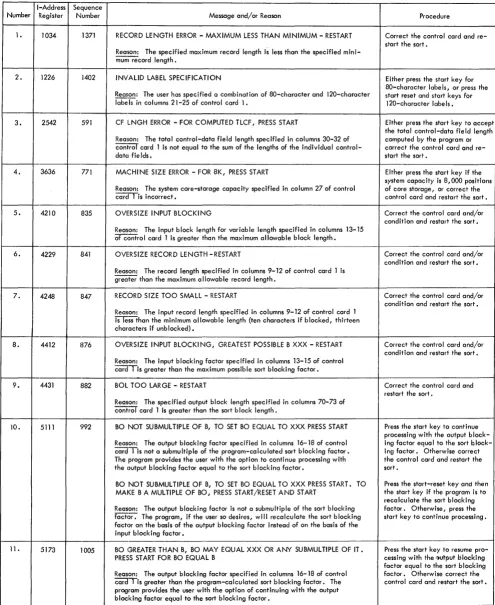
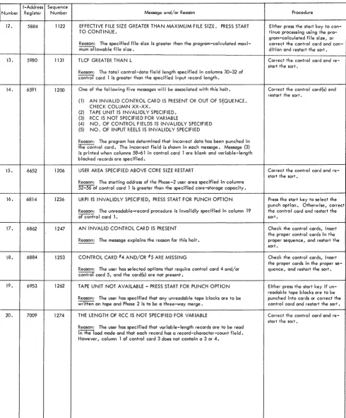
Halts and/or Messages . . . .. 37
Appendix.. . . .. .. . .. . .. . .. . .. . .. . ... .. . ... ... .. .. 50
Standard Tape Labels. . . . .. 50
Arrangement of Input Tapes. . . . 50
Coding Sheet . . . .. 50
Sort 7 for the IBM 1401 and JL 460 Data Processing Sys-tems provides the user with the ability to sort records that are stored on magnetic tape. The sorted records are arranged in collating sequence, either ascending or descending, according to the control data within the records.
Control cards, prepared by the user, modify the gen-eralized Sort 7 program to fit the requirements of a specific sort application. The Sort 7 program can be loaded from cards or tape. An optional program, sup-plied with Sort 7, modifies the card-oriented Sort 7 program and transfers it to tape.
Sort 7 performs tape sorting in two steps. The first step, phase 1, is an internal sort. This means that a number of records in random order are read into core storage from an input tape and then rearranged inter-nally into the desired sequence. As the sequences
(strings) are developed, they are written alternately on two output tapes if four tape units are used in the
oper-ation, or in rotation on three output tapes if six tape
units are used.
The second step, phase 2, consists of a series of
merge passes that results in a sequential tape file. If
four tape units are used for sorting, a 2-way balanced merge or a multiphase merge can be performed. The multiphase merge option reduces overall sort time
when fixed-length records are being sorted. If six tape
units are available, a 3-way balanced merge can be performed.
The Sort-7 program:
• Sorts blocked or unblocked records.
• Sorts fl:xed- or variable-length records (except for the multi-phase option that sorts only fixed-length records).
• Sorts according to control data contained in as many as ten fields of each record.
• Sorts on either numeric or alphameric control data.
• Sorts records in ascending or descending order. The collating sequence is given in the System Operation Reference Manual: IBM 1401 and 1460 Data Processing Systems, Form
A24-3067.
• Allows the user to insert routines that are to be executed dur-ing the Sort 7 program run.
• Processes standard 120-character (Type A) and BO-character (Type B) header and trailer labels on the input file, if desired. • Labels output tapes, if desired, in accordance with
control-card information.
• Provides a checkpoint routine that periodically writes the
Sort 7 Specifications
IBM 1401
and
1460
contents of core storage on tapc and enables the user to stop and restart the program at various stages.
• Sorts as many records at sort blocking as will fit on either one or two reels (depending upon whether four or six tape units are used) of magnetic tape. Input records may be contained on a maximum of 99 reels.
Note: In this publication, the term' standard tape labels
(header or trailer) refers to Type A alld Type B labels. See the tape IOCS specifications publication (See Related Infor-mation) for a description of label processing. Also, see Figure 19: Schematics of Type A and Type B Labels.
Machine Requirements
The minimum machine requirements for the Sort 7 program are:
An IBM 1401 system with:
• 8000 positions of core storage.
• Four IBM 729II, 7291V, 729V, or 7330 Magnetic Tape Units;
five units are required if Sort 7 is to be loaded from tape.
• IBM 1402 Card Read-Punch.
• IBM 1403 Printer Model 2, or IBM 1404 Printer. • High-Low-Equal Compare special feature. • Advanced Programming special feature. • Sense switches.
An IBM 1460 system with:
• 8000 positions of core storage.
• Four IBM 7330, 729II, 7291V, 729V, or 729VI Magnetic Tape Units; five units are required if Sort 7 is to be loaded from tape.
• IBM 1402 Card Read-Punch.
• IBM 1403 Printer Model 2.
• Indexing and Store-Address-Register special feature. • Sense switches.
Three tape units are required to transfer the Sort 7 program from cards to tape. Sense switches A, C, E, and F are used for the Sort 7 tape build job.
Five tape units are required if the Sort 7 program is to be loaded from tape.
Sense switches B, C, D, E, F, and G are used by the Sort 7 program. These switches permit operator inter-vention and options during the running of the program.
Related Information
Input/Output Control System (on Tape) Specifica-tions and Operating Procedures for IBM 1401 and 1460, Form C24-1462.
Autocoder (on Tape) Language Specifications and Operating Procedures for IBM 1401 and 1460, Form C24-3319.
Sorting and Merging Techniques
The sorting technique used by Sort 7 during phase 1 consists of reading a number of records from the input file, arranging them in sequences, and writing these sequences on two or three output tapes. One, two, or three tape units are used for input, and either two or three for the phase 1 output. The tapes that contain
phase 1 output are called work tapes.
Two input units are used if the records to be sorted are contained on two or more reels in a 4-tape sort.
Three input units can be used if the records are
con-tained on more than two reels in a 6-tape sort. Reading input records from more than one tape unit is done al-ternately from two units or in rotation from three units.
For example, if three tape units are used to read input
data from more than three reels, the Sort-7 program reads all of the records from the tape on the first tape
unit. It then reads all of the records from the tape on
the second tape unit, and then all of the records from the tape on the third tape unit. Provision is made to permit the operator to change input reels during phase 1 without interrupting the operation. Thus, on the sec-ond rotation, a fourth reel can be mounted on the first tape unit, a fifth reel on the second, and so forth, until the last reel of the file has been processed.
Any standard header and trailer labels on the input tapes are processed during phase 1. The retention-period field in each work-tape header label is checked
if the user requests the checking in his control card.
The sorted sequences developed by phase 1 are merged into one sorted sequence during phase 2. A series of merge passes are required to complete the sort. The sorted records are reblocked according to the user's specifications and are written as one sequential file on one or more output tapes.
Any temporary header labels on the work tapes are processed at the beginning of phase 2. During the last merge pass, standard header and trailer labels are
de-veloped if the user requests them in his control cards.
Types of Merges
The user has the option of electing either a balanced merge or a multiphase merge during phase 2.
6 Sort 7 Specs. and Op. Proc: 1401 and 1460
Balanced Merge
Normally, a balanced merge technique is used. The multiphase merge option is applicable only when fixed-length records are to be sorted on a four tape system.
When the merge is balanced, the number of input units equals the number of output units for each merge pass. The tape units used for phase 1 input become the output units for the first merge pass. All tapes used during the merging process are considered to be work tapes.
The balanced merge is called a 2-way merge when four tape units are used and a 3-way merge when six tape units are used.
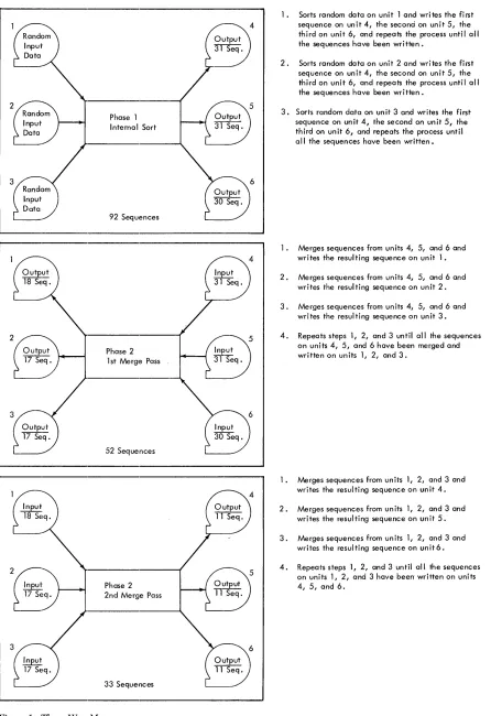
Figure 1 shows the results of a phase 1 internal sort and the first two merge passes in a 3-way balanced merge. The merging process described in Figure 1 is repeated until one sequential file is developed.
Multiphase Merge
The multiphase merge reduces the overall sorting time by 15% to 25% on four tape systems when the input files contain fixed-length records. The actual reduction in sort time depends on the randomness of the initial input data. The user specifies the multiphase merge option by turning sense switch C on before loading the Sort 7 program.
The multi phase merge is an unbalanced merge. That is, the number of input units does not equal the number of output units. The merging technique consists of a series of 3-way merges during which there are always three input units and one output unit.
Sort-7 phase-1 output is contained on two ltape units regardless of the type of merging selected for phase 2.
If a balanced merge is to be used, the merging process
can begin immediately. However, when the multiphase merge program is to be used, the sequences must be redistributed onto three tape units before the merging can begin. The redistribution is done during an adjust-ment phase that follows phase 1 of the sort and actually performs the first phase of the multiphase merge.
Adjustment Phase
The redistribution of the sequences developed during phase 1 is done in accordance with certain calculated values. The calculations are performed using values from a program-generated table shown in Figure 2.
Initially, aI, b1 and Cl in the table are aSSigned values
of 1. Because N at any table level is equal to the sum
of aI, b1 and Cl at that level, N equals three at the first
level and then N
+
3Cl equals six. Higher table levelsare generated using the previous level a1, hI and Cl values. At any table level after the first, al is equal to Cl
2~~
17 Seq.Phase 1 Internal Sort
92 Sequences
Phase 2 1 st Merge Pass
52 Sequences
Phase 2 2nd Merge Pass
[image:7.612.75.521.60.710.2]33 Sequences
Figure 1. Three-Way Merge
1. Sorts random data on unit 1 and writes the first sequence on unit 4, the second on unit 5, the third on unit 6, and repeats the process until all the sequences have been written.
2. Sorts random data on unit 2 and writes the first sequence on unit 4, the second on unit 5, the third on unit 6, and repeats the process until all the sequences have been written.
3. Sorts random data on unit 3 and writes the first sequence on unit 4, the second on unit 5, the third on unit 6, and repeats the process until all the sequences have been written.
1. Merges sequences from units 4, 5, and 6 and writes the resulting sequence on unit 1.
2. Merges sequences from units 4, 5, and 6 and writes the resulting sequence on unit 2.
3. Merges sequences from un its 4, 5, and 6 and wri tes the resul ti ng sequence on un it 3.
4. Repeats steps 1, 2, and 3 until all the sequences on units 4, 5, and 6 have been merged and written on units 1, 2, and 3.
1. Merges sequences from units 1, 2, and 3 and writes the resul ting sequence on un it 4.
2. Merges sequences from units 1, 2, and 3 and writes the resulting sequence on unit 5.
3. Merges sequences from un its 1, 2, and 3 and writes the resulting sequence on unit6.
N+3c, N °1 b1 c1
6 3 1 1 1
11 5 1 2 2
21 9 2 3 4
38 17 4 6 7
70 31 7 11 13
129 57 13 20 24
237 105 24 37 44
436 193 44 68 81
802 355 81 125 149
1475 653 149 230 274
2713 1201 274 423 504
4990 2209 504 778 927
Figure 2. Multiphase Table
sum of al and Cl in the level immediately preceding; and Cl is equal to the sum of the b1 and Cl in the level
immediately preceding.
[image:8.613.46.288.60.327.2]The values generated for N + 3Cl, at each table level are successively compared with S (the total number of sequences developed during phase 1) until a table level is reached where N + 3Cl ~ S. Then generation of suc-ceeding levels ceases. The values aI, b1 , and CI at this
table level are the number of sequences that appear on three of the four available tape units when the adjust-ment phase is complete. If S is six or less, special values are aSSigned by the program.
[image:8.613.303.542.64.322.2]Calculation of the factors required for redistribution of the sequences is performed using the values at the table level where N
+
3Cl ~ S. The redistribution fac-tors are calculated using the following formulas:S-N
Y = - 3 - (rounded to the next lower integer)
X =S-N-2Y
PI
=
Cl - YP2
=
A-X-ClPa
=
A+
k - X - Y - alTo explain these formulas,.it is assumed that during phase 1 the initial input file was read from tape unit 1; that 55 sequences of sorted records were developed; that 28 of the 55 sequences were written on tape unit 3; and that the other 27 sequences were written on tape-unit 4.
8 Sort 7 Specs. and Op. Froc: 1401 and 1460
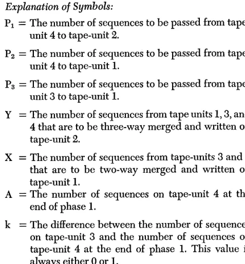
Explanation of Symbols:
PI
=
The number of sequences to be passed from tape-unit 4 to tape-tape-unit 2.P2
=
The number of sequences to be passed fromtape-unit 4 to tape-unit 1.
Ps
=
The number of sequences to be passed fromtape-unit 3 to tape-tape-unit 1.
Y
=
The number of sequences from tape units 1, 3, and 4 that are to be three-way merged and written on tape-unit 2.X
=
The number of sequences from tape-units 3 and 4that are to be two-way merged and written on tape-unit 1.
A
=
The number of sequences on tape-unit 4 at the end of phase 1.k
=
The difference between the number of sequences on tape-unit 3 and the number of sequences on tape-unit 4 at the end of phase 1. This value is always either 0 or 1.The values for N, a1, b1 and Cl from the table are,
respectively, 31, 7, 11 and 13. For this example, al equals the number of sequences on tape-unit 3 after adjustment; bl equals the number of sequences that are on tape-unit 1 after adjustment; and CI equals the number of sequences on tape-unit 2 after adjustment. The computed adjustment values for this example are: PI
=
5; P2=
6; Ps=
5; Y=
8; and X=
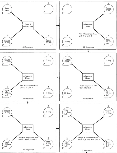
8.The adjustment operations performed using these computed values are shown in Figure 3. The first operation performed is to pass P 1, or a total of 5, se-quences from tape-unit 4 to tape-unit 2. Then P2 , or 6, sequences are passed from tape-unit 4 to tape-unit 1. Next Ps, or 5, sequences are passed from tape-unit 3
to tape-unit 1. The sequences are now distributed on three tapes but further adjustments are required before the multpihase merge can begin. The next operation is a two-way merge during which X, or 8, sequences are merged from tape-units 3 and 4 and then written on tape-unit 1. Then Y, or 8, sequences are three-way merged from units 1,3, and 4 and written on tape-unit 2.
Thus, the required distribution of seven sequences on tape-unit 3, eleven sequences on tape-unit 1, and thirteen sequences on tape-unit 2 is achieved, and the multiphase merge can begin.
Merge
Phase 1
55 Sequences
Adj",tment
I
PhasePass 5 SeqlJences from Unit 3 to Unit 1
55 Sequences
J
Adjustment Phase
Merge 8 Sequences from Units 3 and 4 to Unit 1
47 Sequences
Figure 3. Adjustment Phase
2
0 0
3
8
2
B
4 3
8 8
2
B
Adjustment Phase
Pass 5 Sequences from Unit 4 to Unit 2
55 Sequences
Adjustment Phase
Pass 6 Sequences from Unit 4 to Unit 1
55 Sequences
Adjustment Phase
31 Sequences
Multiphase Merge Program
2
2
8
[image:9.612.81.574.61.706.2]1
8
3
8
D
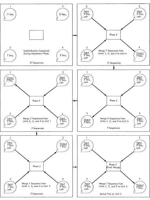
Redistribution Completed During Adjustment Phase
31 Sequences
Phase 2
Merge 2 Sequences from Units 2, 3, and 4 to Unit
5 Sequences
Merge 1 Sequence from Units 1, 3, and 4 to Unit 2
3 Sequences
Figure 4. Multiphase Merge
10 Sort 7 Specs. and Gp. Proc: 1401 and 1460
2
8
4
8
2
2
C
Merge 7 Sequences from Units 1, 2, and 3 to Unit 4
17 Sequences
J
Phase 2
Merge 4 Sequences from Units 1, 2, and 4 to Unit 3
9 Sequences
Phase 2 Final Merge)
Merge 1 Sequence from Units 1, 2, and 3 to Unit 4
Sorted Fi Ie on Unit 4
2
2
2
[image:10.612.46.540.45.704.2]merged from three of the tape units and written on the fourth unit. The merging continues until all of the se-quences on one of the input tapes have been read and merged. This tape is then rewound and becomes the output tape during the next merge phase. The output tape is also rewound and becomes an input tape dur-ing the next phase. This three-way mergdur-ing process continues until the entire file has been merged and written on one tape, which, for this example, is on unit 4.
The specifications entered into the control card( s) are the same whether a balanced or a multiphase method of merging is employed during phase 2. All of the options available when a balanced merge is used are available during a multiphase merge including
INTERRUPT and RESTART. When the program is
inter-rupted during the multiphase-merge operations, the merge phase in process is completed, after which two of the four tapes are rewound automatically. Before the program can be restarted, each tape must be re-mounted on a tape unit with the same number as the one from which it was removed. Restart by pressing the tape-Xoad key.
Tape Loadable Feature
To transfer the Sort 7 program to tape, use the optional program supplied with Sort 7. This program first inserts patch routines that make Sort 7 tape operable and then writes the modified Sort 7 on tape. At object time, patch routines occupy the uppermost 120 positions of core storage. Thus, these positions are not available for user routines.
Three tape units are required for the tape-build job. After Sort 7 has been transferred to tape, the user can perform a tape-update job to modify the tape by in-serting or deleting routines. The update job can also copy the Sort 7 tape. Two tape units are required for the tape update job.
Five tape units are required when Sort 7 is loaded from tape. The Sort 7 tape must be mounted on tape unit 1. A number other than 1 must be selected as the unit number for each of the four remaining tape units. Since four tape units are used for the sort either a two-way balanced merge or a multiphase merge can be performed.
User Programming Feature
Exits are provided at key points within the main line and the input/output portioIlts of the program so the user can set aside areas in phase 1 and/or phase 2 for his exclusive use during the program run. To reserve
these areas, the user must specify the beginning ad-dress of each area in the control cards.
User routines must be written in the 1401-1460 tape Autocoder language, assembled, and punched into cards. If the Sort 7 program resides on tape, the tines must be transferred to the Sort 7 tape. The rou-tines will increase the sorting time because they de-crease the number of core storage positions available for use by the Sort 7 program.
Checkpoint and Restart feature
Conditions may arise which make it necessary to in-terrupt the Sort-7 program before the sorting job being performed is complete. To allow for this possibility, a feature that permits the user to stop processing at cer-tain stages of the sort and later to resume processing at this same point is incorporated into the program.
If processing is stopped during phase 1, all sorting performed up to that point is lost. To restart, it is nec-essary to reload the program deck. During phase 2, a checkpoint record is written before each merge pass begins. Thus, if processing is stopped during phase 2, only the merge pass that is interrupted is lost.
The output of the preceding pass remains intact. When the program is interrupted, the user must save the output reels from the last pass and the reel contain-ing the checkpoint.
file Requirements
This section discusses the general characteristics of files that can be processed by Sort 7. The maximum file size depends on the record length, the sort blocking factor (number of records per block), and the density of the tape. See User Calculations.
Allowable Record Configurations
Sort 7 processes either fixed-length or variable-length records. The minimum record length is 13 characters for unblocked records and 10 characters for blocked records. The maximum record length per blocked or unblocked records is 3999 characters. When sorting variable length records with more than one control field and/or in descending order, the maximum record length or block length that can be handled is 3400 characters. There are four different record formats that the program, can handle. A record mark follow-ing the last character of each record is optional.
The following terms are used in the description of the acceptable formats:
Block Character-Count Field: A four-character block
character-count field itself. The character-count, which must contain AB zone bits over the units position of the field, is used for checking for wrong-length record conditions.
RecQrd Character-Count Field: A record
character-count field of 3 or 4 characters in each data record con-tains a count of the number of characters in that record, including itself. This field must be in the same relative position in each data record, and must be the same length in each data record of a given file.
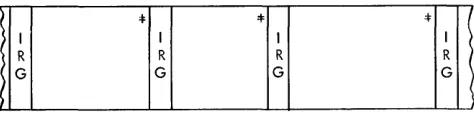
Form-l Records
Form-l records (Figure 5) are fixed-length and are written on tape unblocked.
:I: :I: 4=
I I I I (
R Ll R L2 R L3 R
G G G G )
> (
Figure 5. Form-l Records
Form-2 Records
Form-2 records (Figure 6) are fixed-length and are written on tape in blocks. Padding records must be added to short-length blocks.
:I:
Figure 6. Form-2 Records
Form-3 Records
Form-3 records (Figures 7 and 8) are variable-length and written on tape unblocked. Each record can have a Record Character Count (RCC) field.
~ I :f I
'*
I '1=R: I R:
I I RI I I
j R CI I R C: R C ' R
C:
I
i G CI G G C' G
I I I
I I
< I I I I I I I
Figure 7. Form-3 Record with a Record-Character Count Field
Figure 8. Fom1-3 Records without a Record-Character Count Field
12 Sort 7 Specs. and Op. Froc: 1401 and 1460
If Form-3 records without record character count fields are specified for input, a record character count field is added at the beginning of each record (first four characters) by Sort 7 for internal processing. If the specified output record format in this case is equiva-lent to the input record format (that is unblocked), the added record character count field is normally deleted, and the records are restored to their original lengths.
If, however, blocked output is specified, the record character count field added by Sort 7 is always retained.
Form-4 Records
Form-4 records (Figure 9) are variable-length, and written on tape in blocks. Each record contains a rec-ord character count field and each block contains a Block Character Count (BCC) field.
Jill
}
: :
*'
:
I 4= I I~ I B I I R I I I I R I I I I R I I
( R C : C: IC: : C:
~GC
IC I IC I I I I C:I I
I I : I I I
I I I I I I
I-Record A
-1--
Record B-1-
Record C - IFigure 9. Form-4 Records
Restrictions
Records may contain any alphameric characters or special symbols except:
1. Tape mark as the first character of a record.
2. Record mark within a record. A record mark as the last character of each record is permissible but not mandatory.
3. A group mark.
4. A word separator. It is possible to have a word-separator character on tape if the tape is to be read in load mode. In this case the word separator reads into storage as a word mark over the character it precedes on tape. A word mark must occur in either the high-order position of a control data field, in the first position of the record, or, in the case of variable-length records, in the high-order position of the record character count field. Care must be taken to make certain that all control positions and the record length are specified correctly in this case.
Control Data Fields
[image:12.613.47.291.205.303.2] [image:12.613.309.547.297.366.2] [image:12.613.49.290.382.460.2] [image:12.613.53.289.552.607.2] [image:12.613.53.290.633.690.2]in the same place in each record. The total length of all control-data fields may be as large as 999 characters. The location of each control-data field must be speci-fied by the user in the control cards. If more than one field is used, the user must specify which field is to be compared first (major), which' second (intermediate or minor), and so forth.
Padding
The term padding refers to records added to a file to be sorted when the number of records in the file is not a multiple of the input blocking factor. These addi-tional records are generated internally by the Sort,-7 program. Padding does not occur in the case of vari-able-length records.
Sort 7 automatically adds padding records to an input file if, after reading into storage the last block of records during phase 1, it finds that there are insuffi-cient records to fill the processing area. Enough padding records are generated to fill the remainder of the proc-essing area. Padding records generated by Sort 7 are sorted and merged in the same manner as data input records. They must, therefore, be composed' either en-tirely of nines or enen-tirely of blanks. The user's choice must be punched in one of the control cards. If they contain nines, they will be the last records (ascending sequence) or first records (descending sequence) of a sorted file. If they contain blanks, the opposite results will be obtained.
The SOllt program checks only the control data fields to detennine padding records in the actual sorting or merging phases. A record mark may be the last char-acter of each padding record generated, if the user so specifies.
Tape Den!sity
The Sort-7 program processes input reels written in either high- or low-density mode. The final output reel or reels may be written in either density, although high density is recommended. The user need only set the density switch of the output tape unit to the density desired.
Note: If processing is performed in the high-density mode and the Rna I output is in low density, the Rnal output may re-quire more than one full reel of magnetic tape for a two-way merge, or more than two full reels for a three-way merge. In this situation, the program halts when an end-of-reel is en-countered during Rnal output. The user may then mount a new tape and continue.
Input/Out'put Mode
Unless otherwise specified by the user in the control cards, the input tape(s) are assumed to be written in move mode. Tapes written in load mode can be proc-essed by Sort 7 only if any word marks for the input
data are in the high-order position of any control data field, in the beginning of a record, or in the high-order position of the record character count field. Records with word marks in any other position, and written on tape in the load mode, cannot be processed.
Sort 7 writes the phase-2 sorted output on tape in either move or load mode, depending upon the needs of the user. An output file written in load mode con-tains word marks over the high-order position of all control fields and over the first character of each record.
Sort Program Control Totals
In balanced sorting, all records in the file are read and written during each phase-2 merge pass. For this rea-son, a record count may be maintained during each pass and compared against the count from the previous pass to make certain records have not been dropped or added. If the counts differ, a halt will occur. The user, at this point, may restart the pass or continue with the sort.
In multiphase sorting, the number of records read and written during each phase-2 merge pass will vary.
It is only during the last merge pass that all the records in the file will be handled. Therefore, it is impossible to provide an internal check from pass to pass. Instead, the phase 1 record count is compared to the record count taken during the final merge pass. If the counts differ, the end-of-sort message containing the record count will indicate that an error condition exists.
Unreadable Input Records
Tape records or blocks are considered unreadable when they contain one or more characters that cause redundancy indications after one hundred attempts have been made to read them. A wrong length record is not a redundant record and is not treated as such by the Sort-7 program.
Input tape blocks that are unreadable may be treated in a variety of ways, depending upon information spec-ified by the user in the control cards. The Sort-7 pro-gram:
1. Writes the unreadable block on tape.
2. Punches it into cards, or
3. Prints the block on the printer.
Tape
Labels
Sort 7 can process standard 120-character (Type A) and standard 80-character (Type B) header and trailer tape labels. See the tape laCS specifications publication for a description of tape labels and label processing. Also, see Figure 19: Schematics of Type A and Type B Labels. The user can specify the kind of processing
de-sired by means of the control cards.
Nonstandard header and trailer labels (not exceed-ing 120 characters in length) on the input tapes can be bypassed by Sort 7, or the labels can be processed by user routines. Exits are provided at convenient points to permit the inclusion of the user routines.
Input Header Labels
The Sort-7 program, depending upon control-card in-formation, either bypasses or checks standard header labels on the input tapes. The user can specify that full label-checking or checking of just the file name be per-formed on each input header label. The file serial num-ber, reel-sequence numnum-ber, file name, and creation date are checked when full label-checking is specified.
When the input tapes contain nonstandard header labels, the user must specify in the control cards that the input tapes contain header labels and that label checking is not to be performed. Then, if the user does not insert a routine to process the nonstandard labels, the Sort-7 program bypasses the header labels.
If the user specifies in the control cards that the input tapes contain header labels, then all input tapes must contain a header label. The header labels on all tapes must conform to the user specifications on the control cards.
Work-Tape Header Labels
The work tapes for phase 2 of the Sort-7 program can contain standard header labels, or temporary header , labels, or no header labels.
If the work tapes contain standard header labels, the user is permitted to specify that the sort check the retention cycle of the tapes. This safeguards master tape(s) that may still remain on the input tape unit(s) at the beginning of phase 2.
The work tapes can have temporary 80-character header labels that have the following format:
Positions
1-4
5
6-10 11-80
Contents
IHDR
Blank
Tape serial number
Blanks
14 Sort 7 Specs. and Op. Proc: 1401 and 1460
The work tapes can have temporary 120-character header labels that have the following format::
Positions Contents
1-4 IHDR
5 Blank
6-30 Blanks
31-35 Tape serial number
36-120 Blanks
If the user specifies that the work tapes do not con-tain labels, Sort 7 writes a temporary header label on each work tape.
Output Header Labels
The user can specify that standard header labels be written on the output tapes. The user can further spec-ify, in the control cards, that these header labels con-tain either the information from the header label on the first input tape or information supplied by the user in a control card.
The information in positions 1-40 of the header label on the first input tape, with the exception of the crea-tion date, can be duplicated in the header label written on each output tape. The current date, which must be punched in a control card, is written in the creation-date field of the output header labels.
If an entirely new standard header label is to be written on the output tapes, the user must punch the header-label information, with the exception of the tape serial number, into a control card. If the new label is to be a standard 80-character label, the user has the option of either punching a tape serial number into the control card or having the program place the tape serial number from the output tape into the new header label. This option is not available for standard 120-character labels.
Input Trailer Labels
Standard trailer labels on input tapes can be either by-passed or processed by Sort 7. If the user specifies that either 80-character or 120-character trailer labels are to be processed, the label is read, the label information is printed, and the block count maintained by the pro-gram is compared with the block count from the trailer label. If 80-character trailer labels are specified, the record count maintained by the program is also com-pared with the record count from the trailer label.
process-ing of nonstandard labels must be done by a user routine.
Trailer labels are not maintained on the Sort 7 work tapes.
Output frailer Labels
Sort 7 and Merge 7 generate standard trailer labels and write them on the output tapes, if the user so specifies. Each generated output trailer label contains an end-of-reel or an end-of-file indication and a block count that is maintained by the program. The eighty character label also contains the record count that is accumu-lated by the program. Any further output trailer-label processing must be done by user-inserted routines.
Label Error Procedures
The Sort 7 program prints each input tape label the first time it is reac!. If an error is found when the pro-gram is checking either an input header label or an output header label, a message is printed and the pro-gram haIts. The user can then either mount the correct tape and cause the program to check the header label on this tape or continue the operation with the incor-rectly labeled tape. In the latter case, the program continues as if the tape were labeled correctly.
Sort 7 halts if the program-generated block count does not equal the block count contained in the input trailer label being checked. The user can then either accept the program block count as valid and continue the operation or check the input tape by editing it or making a rerun.
A similar halt occurs if a discrepancy is found when the record count maintained by the program is com-pared to the record count located on 80-character trailer label. There is no record count field on the 120-character label.
User Calculations
The Sort 7 program calculates and prints out the values of the following constants:
1. For fixed-length record applications:
B is the sort blocking factor used by Sort 7. BL is the length of the sort block.
MFS is the maximum file size.
G is the number of records sOlted internally at one time.
2. For variable-length records:
BLmnx which is the maximum length of a sort block. MFS is the maximum file size.
The user can calculate the values of these constants by using the formulas given in this section.
Fixed-Length Records
This section contains the formulas that can be used to determine the sort blocking factor (B), the sort block length (BL), the number of records sorted internally at one time (G), and the maximum file size (MFS).
Sort Blocking Fador
For a given application, the Sort 7 program calculates the sort blocking factor (Bactual). The user can deter-mine Bactual if the maximum allowable blocking factor (Bmax) and the users' input blocking factor (BI) are known. Calculate Bmax as follows:
_ 1ST - PS2 - UA2--12! Bmax - [ (M+l) L
J
where
L
J
means rounded low.ST
=
Core storage capacity of the 1401 or 1460 system.PS2
=
Number of core storage positions required by phase 2 of the Sort 7 program.This value is:
3925 for a balanced merge with standard label processing.
3225 for a balanced l'nerge without standard label processing.
3215 for a multiphase merge with standard label processing.
2815 for a multiphase merge without standard label processing.
UA2
=
Number of core storage positions required for user programming in phase 2. If a user area is not re-quired, and1. The program is on cards, UA2
=
O. 2_ The program is on tape, UA2=
120.M
=
Type of phase 2 merge. This value is: 2 for a four-tape balanced merge.3 for a multi phase merge (four-tape sort only). 3 for a six-tape balanced merge.
L
=
Record length.After Bmax has been calculated, Bactual can be deter-mined using the following formula:
LBmax! Bactual
=
L13IJ
(BI)Where BI
=
the user's input blocking factor. BI should be equal to or a factor of Bmax.The value of the output blocking factor (BO) must
Optimum Input Blocking Factor
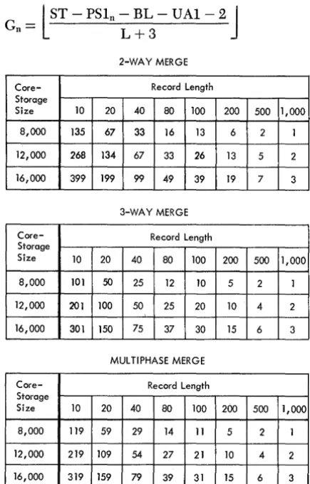
The Sort-7 optimum input blocking factor (BI) is the actual sort-blocking factor (B) used in phase 2 of the program. The optimum input blocking factors shown in Figures 10 and 11 are based on the assumptions that fixed-length records are being sorted, and that a user-written routine has not been inserted in phase 2.
Number of Records Sorted Internally
The number of fixed-length records that can be sorted internally at one time (Gaetual) can be determined if
the sort block length (BL) is known. Calculate BL as follows:
BL
=
(Baetual)(L)where Baetual
=
Blocking factor determined by Sort 7L
=
Record lengthBL should be calculated for each sort application. The minimum BL is 400 characters; the maximum BL is 3999 characters.
The calculation of Gaetual is an iterative process that uses the formula:
l
ST - PSln - BL - U Al - 2J
Gn=
L + 32-WAY MERGE
Core- Record Length Storage
Size 10 20 40 80 100 200 500 1,000
8,000 135 67 33 16 13 6 2 1
12,000 268 134 67 33 26 13 5 2
16,000 399 199 99 49 39 19 7 3
3-WAY MERGE
Core- Record Length Storage
Size 10 20 40 80 100 200 500 1,000
8,000 101 50 25 12 10 5 2 1
12,000 201 100 50 25 20 10 4 2
16,000 301 150 75 37 30 15 6 3
MUL TlPHASE MERGE
Core- Record Length Storage
Size 10 20 40 80 100 200 500 1,000
8,000 119 59 29 14 11 5 2 1
12,000 219 109 54 27 21 10 4 2
[image:16.617.304.521.66.364.2]16,000 319 159 79 39 31 15 6 3
Figure 10. Optimum Input Blocking Factors when Tape Label Processing Is Specified
16 Sort 7 Specs. and Gp. Proc: 1401 and 1460
2-WAY MERGE
Core- Record Length Storage
Size 10 20 40 80 100 200 500 1,000
8,000 158 79 39 19 15 7 3 1
12,000 292 146 73 36 29 14 5 2 16,000 399 199 99 49 39 19 7 3
3-WAY MERGE
Core- Record Length Storage
Size 10 20 40 80 100 200 500 1,000
8,000 119 59 29 14 11 5 2 1
12,000 219 109 54 27 21 10 4 2
16,000 319 159 79 39 31 15 6 3
MULTIPHASE MERGE
-Core- Record Length Storage
Size 10 20 40 80 100 200 500 1,000
8,000 129 64 32 16 12 6 2 1
12,000 229 114 57 28 22 11 4 2
16,000 329 164 82 41 32 16 6 3
Figure 11. Optimum Input Blocking Factors when Tape Label Processing Is Not Specified
where
L
J
means rounded low.UAI = Number of core storage positions required for user programming in phase 1. If a user area is not required and
1. The program is on cards, U Al
=
O.2. The program is on tape, U Al
=
120.Note: G is never greater than 2B when multiphase merging is
used.
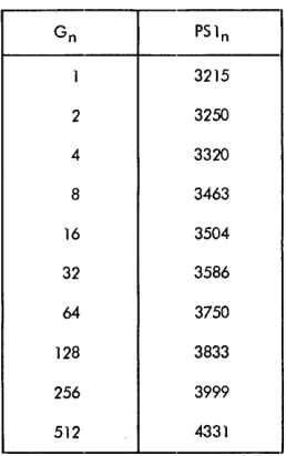
During each iteration, a value is calculated for Gn based on a PSln value that is obtained from the chart in Figure 12. The iterations cease when two successive calculated Gn values fall within a particular range of Gn values shown in Figure 11. The last calculated Gn value is then used in the following formula to calcu-late Gaetual.
l
GnJ.
Gaetnal = -B-- (Baetnal)actual
The method of calculating Baetual and Gaetnal is shown in the following example. Assume that fixed-length records are being sorted, a balanced merge with label processing is being used, and that:
[image:16.617.46.264.349.689.2]Gn PS 1n
1 3215
2 3250
4 3320
8 3463
16 3504
32 3586
64 3750
128 3833
256 3999
[image:17.612.75.204.56.262.2]512 4331
Figure 12. Values of G and Their Associated Phase-1 Program Sizes
L= 100
Bt=3
M=2
UA1=0 UA2=0
Then:
_l~L6000 - 3925 - 0 - 6J _ Bmax - 3 (100)
-B,,'unl =
l
~
J
(3),=
(13) (3)=
39BL = (39) (100) = a900
1}2069J _
L
300 - 40Then, using the first value of PSln shown in the chart:
= l16000 - 3215 - 3900 -- 0 - 2
J
= l8883J
= 86 G1103 103
For the next iteration, use the PSln value that is
shown opposite the upper limit of the range in which G1 falls. Thus, PSln for the next iteration is 3833 be-cause 26
<
G1
<
27.Then:
_l16000 - 3833 - 3900 -- 2
J -
l8265J
-G2 - 103 - 103 - 80
Because G1 and G2 are within the same range in the
chart (26
<
G2
< G
1< 27), the iterations cease. Gaetual
is calculated using the last calculated Gn value (80).
C,,'unl
=
l:~J
(39)=
(2) (39)=
78.Maximum File Size
The input file to be processed by Sort 7 must be no longer than the number of records that can be con-tained on one reel (if phase 2 is a two-way merge or a multiphase merge), or on two reels (if phase 2 is a three-way merge). This number depends on record length, the sort blocking-factor, and whether process-ing is performed in the low- or high-density magnetic-tape mode. It ca.n be determined as follows:
R
=
K X B (N-1)(B X L)
+
IRGExplanation of Symbols:
R = Maximum number of input records.
K = Number of usable character positions per tape reel (assume 2,300 feet).
High-density tape: 22,080,000. (800 characters per inch). High-density tape: 15,350,000.
(556 characters per inch). Low-density tape: 5,520,000.
(200 characters per inch).
B = Sort blocking-factor.
L = Record length (if fixed) or maximum record
IRG
N
length (if variable).
= Number of character locations per interrecord gap (.75").
High-density tape: 417. Low-density tape: 150.
= Type of phase 2 merge. This value is:
2 for a four-tape balanced merge (2-way merge).
2 for a multiphase merge (four-tape sort only). 3 for a six-tape balanced merge (3-way merge).
Variable-Length Records
This section contains the formulas that can be used to determine the maximum sort block length (BLmax), the maximum number of core storage positions used for internal sorting (GLmax), and the maximum file size (MFS).
Maximum Sort Siock Length
For a given application, the Sort 7 program calculates the maximum sort· block length (BLmax). An actual blocking factor cannot be calculated since it will vary depending on the record length.
Calculate BLmax using the following formula:
See Fixed Length Records: Sort Blocking Factor for
an explanation of the symbols used in the formula. BLmax must not be greater than 3,999 characters or less than 400 characters.
Core Storage Used for Internal Sorting
The user should determine the maximum number of core storage positions used for internal sorting (eLmax)
if he plans to use his own routines with Sort 7.
First calculate the value of e. V se the following
for-mula for en and perform the necessary iterations until two successive calculated en values fall within a par-ticular range of en values shown in Figure 12.
en
=
lST - PSln - BLmax - VAl-2J Lmin + 3Multiply the last calculated en value by Lm1n to de-termine e Lmax.
See Fixed Length Records: Number of Records Sorted Internally for explanations of the iterative
proc-ess and the symbols used in the formula.
For example, assume that a 3-way balanced merge with label processing is being used and that:
ST
=
12000Lmax
=
150Lm1n
=
15VAl
=
3000VA2
=
2000BiLmax
=
900Then:
BLmax
=
l
12000 - 3925 - 2000 - 8J
3+1=
l~7
J
= 1516For the first iteration, use PSln
=
3215:e
1
=
l12000 - 3215 - 1516 - 3000 - 2J 15+3=
l4:7
J
=
237
Thus, PSln
=
3999 for the next iteration:_112000 - 3999 - 1516 - 3000 - 2J e2
- [ 15+3
=
l3~~
J
=
19318 Sort 7 Specs. and Op. Proc: 1401 and 1460
Because 27
< e
2< e
1< 2
8 e Lmax is calculated usingthe value of e2 :
eLmax = (193) (15)
=
2895Maximum File Size
The formula for estimating the maximum file size is the same as for fixed-length records.
User Programming
The user can write his own routines and incorporate them in the Sort 7 program. Exits, in the form of four-character no-op instructions, are provided at various points in the program. These no-op instructions can be easily changed to unconditional branches so that, dur-ing the runndur-ing of the program, user-written routines can be executed.
A user's program in phase 1 tends to decrease the number of records that can be internally sorted (e). One included in phase 2 decreases the sort block length (BL). Therefore, these programs should be kept to a minimum so as not to affect sorting time to any great extent.
If the multiphase merge option is elected:. user pro-gramming routines can be incorporated in phase 1 as usual. However, a routine incorporated in phase 2 must be associated with the final merge phase only.
A user routine should be written in IBM 1401-1460
tape Autocoder language and be assembled by the tape Autocoder processor.
If Sort 7 is to be loaded from tape, column 78 must not be used. The last instruction of each routine must be a branch back to the next sequential instruction in the Sort-7 program. After the routine has been assem-bled and a condensed object deck has been punched, the first three cards and the last card of the object deck should be removed. These are the clear-storage cards 1 and 2, the bootstrap card, and the clear-and-branch card.
To use any exit, the user punches a patch card that contains a branch instruction which overlays the no-op instruction. The format of the patch card is:
Columns
1-4
5-39
Contain
BIll
Blanks
Explanation
40-46 L004XXX This instruction loads the branch instmction from columns 1-4 of this card into core storage. The posi-tions indicated by XXX contain the address (actual machine language) of the rightmost position of the no-op instruction.
47 -67 NOOOOOONOOOOOONOOOOOO
68-71 1040
72-80 Blanks
If index registers 1, 2, or 3 are to be used during
the execution of the user routine, the contents of the register( s) must be saved. After the user routine has been executed and before the branch back to the next sequential instruction of the Sort-7 program, the con-tents of the index register(s) must be restored.
If Sort 7 is to be loaded from cards, the patch card
followed by the user's object deck must be inserted in
the Sort "1 program deck.
If Sort 7 is on tape, an ALTER card is also required
for each user routine, or group of routines that is to be inserted between the same EX (execute) statement, that is to be transferred to the Sort 7 tape. The format of this card is:
Columns Contain
16-20 ALTER
21-24 Object card sequence number
25-26 Blank
Explanation
This is the card sequence number of the next EX (execute) state-ment after the no-op instruction on the program listing. The card
se-q~~nce number must be four dIgItS.
The ALTER statement, the patch, and the user rou-tine must be transferred to the Sort 7 tape by means of an update job.
Two programmed exits facilitate the addition of user programs to the program tape.
1. Label--USERE1, location--0413, sequence number -150.
This exit is available during the tape-build and
tape-update operations. It can be used to add
pro-grams or routines to the program tape. When it oc-curs, tape unit 3 has been rewound and group marks
have been placed in core-·storage positions Bl and
IBl, as well as in the uppermost core position in the system.
The core-,storage area between positions 3500 and 7500 is available for the program to be added. Insert the branch card and the routine between card num-ber 0080 and card numnum-ber 0081.
2. Label-USERE2, location-2374, sequence number
-525.
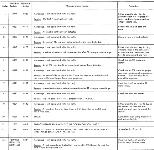
This exit follows the halt that results when the tape-load key is pressed after halt 005 (see Figure
13). It enables the user to add programs or routines
to the program tape. To get to the branch operation, the user must press the start-reset key and then the start key.
The core-storage area between positions 3500 and 7500 is available for the program to be added. Insert the branch card and the routine between card
num-ber 0080 and card numnum-ber OOBI.
If the user routines are assembled before Sort 7 is
transferred to tape, the user can insert the routines in the Sort 7 deck and transfer both to tape by means of a build job. In this case, no ALTER cards are required. The starting address of the phase 1 and/or phase 2 user programming area(s) must be specified in the con-trol card. The user should subtract the number of posi-tions reqUired for his routines from the upper core stor-age limit (7999 for 8K, 11999 for 12K, 15999 for 16K).
If Sort 7 is to be loaded from tape, the uppermost 120
positions are used by Sort 7. In this case, add 120 to the number of positions required for the user routine(s) before determining the starting address of the phase 1 and/ or phase 2 user programming area( s).
Because Sort 7 uses the print area in core storage for label processing, the user is responsible for saving any data that may be in that area at the time his routine is initiated. This data must be restored in the print area before completion of the user's routine.
This section describes the exits available during the assignment phase, phase 1, and phase 2. The program-listing sequence number and the core-storage address of the leftmost position of the no-op instruction are shown for each exit. The branch instruction punched in the patch card is loaded into core storage in the loca-tions that contain the no-op instruction for the exit.
If the routines are to become part of the Sort 7
pro-gram deck, they must be inserted between the appro-priate cards. The sequence numbers of the cards are given for each exit or group of exits.
If Sort 7 is to be loaded from cards, the uppermost
two positions in phase 1 and the uppermost 16 positions in phase 2 (multiphase) and the uppermost 22 posi-tions ill phase 2 (balanced) are used by the Sort pro-gram and are not available for user routines. These positions should be taken into consideration when the starting addresses of the user areas are determined. Assignment Phase
This exit is available in the assignment phase after the dump tape (specified in column 19 of control card 1) has been rewound. This exit can be used to process a label on the dump tape if desired.
Insert the patch card and the assembled user rou-tine for this exit between cards 0272 and 0273. Core storage usable for this routine is available between positions 1570 and 3975.
Sort 7 generates a work-tape header label on the dump tape if the dump-tape option is speCified.
Phase-l Exits
The lowest core-storage position that can be reserved for user programming in phase 1 when fixed-length records are being sorted can be determined using the formula:
Low~s.t core-~torage
=
PSI + BL + GL + 6 pOSItIon aVailableWhere:
PSI
=
The PSln value in Figure 1 that is shown op-posite the upper limit of the range within which Gaetual is contained. This value is 3833 for the example in Fixed-Length Records.When variable-length records are being sorted, sub-stitute BLmax for BL and GLmax for GL in the preced-ing formula. PSI for variable-length records is the PSln shown opposite the upper limit of the range within which G2 is contained.
Use exits 1-4 for processing standard 80-character labels or nonstandard labels with 80 characters or less. Insert the patch card(s) and the assembled user rou-tine(s) between card 0398 and card 0399.
1. Label- EXIT7, location - 2481, sequence num-ber-1795.
This exit is available in the label-handling rou-tine after an input header label has been read and checking, if specified, has been performed. This exit may be used to:
a. Perform additional checking of the header label. b. Process a nonstandard header label, or,
c. Read any additional header labels on the input tape.
The low-order position of the header label that has just been read is 201, the high-order position is 280. The first 40 positions of the first header label are stored in positions 422-461, if a 1 is punched in column 22 of control card l.
The contents of positions 201-280 are printed during the label-handling routine.
20 Sort 7 Specs. and Gp. Proc: 1401 and 1460
The user should punch a 1 in column 21 of con-trol card 1 if this exit is to be used to work on non-standard header labels.
Note: The lowest core-storage position available for
read-ing the first header label is 6500. The formula for calculat-ing the lowest core-storage position is inapplicable because the EXIT7 instruction is executed before the complete initialization of phase 1. However, the formula is applicable for reading header labels after the first.
2. Label- EXITO, location - 4334, sequence num-ber-2078.
This exit is available before any work-tape labels are created or read, if labels are specified.
Work-tape labels will be written on the output tapes if they are specified in column 4 of control card 3 or if columns 21-25 of control card 1 are not left blank.
The low-order position of the label is 4175 (WLAREA - 29). The high-order position is 4254 (WLAREA + 50). After this exit, the labels will be read and checking, if specified, will be performed.
If positions 4175-4254 do not contain a label, a temporary label will be constructed in these posi-tions. Thus, this exit can be used to create labels before label checking.
3. Label - EXIT5, location - 4658, sequence num-ber-2144.
This exit is available in the label-handling rou-tine just before the writing of an output header label. If work-tape labels are specified:
a. The label has been read, and
b. Retention-cycle checking has been performed, if
specified.
If work-tape labels are not specified, a tempo-rary work label has been set up in the label area ready to be written as an output header label.
Any modification or checking of the work-tape header label can be performed at this time.
This exit can also be used to produce the output header label on the work tapes. The label is written from WLAREA - 29 (4175). The user has 80 posi-tions (4175-4254) for a nonstandard header label. A group mark can be found at WLGM (4256).
4. Label- EXIT9, location - 4707, sequence num-ber-2154.
This exit is available after the phase-l work-tape labels have been written.
or less. Insert the patch card(s) and the assembled user routine(s) between card 0442 and card 0443.
5. Label- USEXT7, location-2481, sequence num-ber·-2264.
This exit is available in the label-handling rou-tine after an input header label has been read and checking, if specified, has been performed. This exit may be used to:
a. Perform additional checking of the header label.
b. Process a nonstandard header label, or
c. Read any additional header labels on the input tape.
The low-order position of the header label that has just been read is 201? the high-order position is
320. The first 40 positions of the first header label
are stored in positions 42,2-461, if a .3 is punched in column 22 of control card 1.
The contents of positions 201-320 are printed during the label-handling routine.
The user should punch a .3 in column 21 of con-trol card 1 if this exit is to be used to work on non-standard header labels.
Note: The lowest core-storage position available for read-ing the first header label is 6500. The formula for calculat-ing the lowest core-storage position is inapplicable because the USEXT7 instruction is executed before the complete initialization of phase 1. However, the fonnula is applicable
for reading header labels after the first.
6. Label- USEXTO, location-4.381, sequence num-ber -- 2.3.39.
This exit is available before any work-tape labels are created or read, if labels are specified.
Work-tape labels will be written on the output tapes if they are specified in column 4 of control card 3, or if columns 21-25 of control card 1 are not left blank.
The low-order position of the label is 4175
(WLAREA - 29); the high-order position is 4294
(WLAREA + 90). After this exit, the labels will be read and checking, if specified, will be performed.
If positions 4175-4294 do not contain a label, a temporary label will be constructed in these posi-tions. Thus, this exit can be used to create labels before label checking.
7. Label- USEXT5, location - 4659, sequence num-ber -- 2.398.
This exit is available in the label-handling rou-tine just before the writing of an output header label. If work-tape labels are specified:
a. The label has been read, and
b. Retention-cycle checking has been performed, if
specified.
If work-tape labels are not specified, a temporary work label has been set up in the label area ready to be written as an output header label.
Any modification or checking of the work-tape header label can be performed at this time.
This exit can also be used to produce the output header label on the work tapes. The label is written from WLAREA - 29 (4175). The user has 120 posi-tions (4175-4294) for a nonstandard header label. A group mark can be found at MAGMWL (4296).
8. Label- USEXT9, location - 4708, sequence num-ber-2407.
This exit is available after the phase-l work-tape labels have been written.
9. Label- USEXT6, location - 2658, sequence num-ber -2.305.
This exit is available just after the standard
120-character input trailer label is read and checked, if
specified. Any additional checking can be per-formed at this time.
This exit also can be used to read or process any additional trailer labels that have 120 characters or less. Core storage positions 201-320 contain the trailer label.
N ate: Column 24 of control card 1 should contain a 3
if the user wants to process nonstandard trailer labels with 120 characters or less.
Insert the patch card( s) and the assembled user routine(s) for exits 10-13 between card 0632 and card 0633.
10. Label - PUTEXT, location - 1405, sequence number -1571.
This exit occurs before records are moved from the input area to the output area. Index-register 1 contains the core-storage address of the beginning of the input record.
11. Label - RITEXT, location - 1657, sequence number -1628.
This exit is available immediately before writing a block of records on one of the output tapes. Core storage positions 1665-1667 contain the starting ad-dress of the output area.
This exit is available after a tape record has been read and the associated error-checking is complete except for the wrong-length record check. Index-register 3 contains the core-storage address of the beginning of the input block. Index-register 1 con-tains the core-storage address of the group mark that was placed one position to the right of the last character of the block.
The exit can be used to perform:
a. Record modification or editing. Do not change
the length of fixed-length records. If variable-length records are modified in length, be certain that both the record character count and block character count (if either is present) reflect the change. Also, modify the contents of index-register 1 accordingly, and relocate the group mark.
b. Deletion. The entire block can be deleted by
branching the program to the instruction labeled NOISRT, location 2043, sequence-number 1710, in the tape read routine. If only selected records within the block are to be deleted, additional pro-gramming is required.
The user should insert blanks or nines in the con-trol data field( s) of the record( s). The record can be deleted during the final output phase if an entire block of such records exits.
c. Record-length check. The user can insert a
rou-tine to check the length of variable-length records. Sort 7 does not check the lengths of variable length records.
13. Label - EXIT6, location - 2680, sequence num-ber-l836.
This exit is available just after the standard
BO-character input trailer label is read and checked, if specified. Any additional checking can be per-formed at this time.
This exit also can be used to read or process any additional trailer labels that have BO characters or less. Core storage positions 201-2BO contain the trailer label.
Note: Column 24 of control card 1 should contain a 1
if the user wants to process nonstandard trailer labels with 80 characters or less.
Phase-2 Exits
This section describes the exits that are available for user-written routines during phase 2.
Phase-2 user-written routines should be placed into core storage above position 7000 for balanced merging and above 6000 for multiphase merging. This is neces-sary because the checkpoint record routine in this phase requires core-storage positions below this location.
22 Sort 7 Specs. and Op. Proc: 1401 and 1460
Exits 1, 2, and 3 are available in the routine that processes standard BO-character labels on the work tapes (phase 2 prephase). These exits can be used re-gardless of which merging technique is employed in phase 2. Insert the patch card(s) and assembled user routine(s) for exits 1, 2, and 3 between card 0690 and card 0691.
1. Label-EXDT AP, location-83l, sequence num-ber-3566.
This exit is available just before phase 2 is loaded into core storage. It can be used to process the header label on the dump tape.
2. Label-PREIPX, location-l090, sequence num-ber-3612.
This exit is available after the input header label has been read. Any checking of the label can be per-formed at this time. The low-order position of the label that has just been read is 700 (SWKLBA). The high-order position is 779. Position TBO contains a group mark.
3. Label-PREOTX, location-l308, sequence num-ber-366l.
This exit is available after the output header label (on the work tape) has been read and before it is written. The label can be modified, if desired, at this time. The low-order position of the label is 700 (SWKLBA); the high-order position is 779. Position TBO contains a group mark.
Exits 4, 5, and 6 are available in the routine that processes standard 120-character labels on the work tapes (phase 2 prephase). These exits can be used regardless of which merging technique is employed in phase 2. Insert the patch card(s) and assembled user routine( s) for exits 4, 5, and 6 between card 0726 and card 0727.
4. Label-EXET AP, 10cation-852, sequence num-ber-3775.
This exit is available just before phase ~2 is loaded into core storage. It can be used to process the header label on the dump tape.
5. Label-PRAIPX, 10cation-ll04, sequence num-ber-3820.
6. Label-PRAOTX, location-1319, sequence num-ber--3866.
This exit is available after the output header label (on the work tape) has been read and before it is