GA23-0059-0
File No_ 8360/8370/83/4300/8100-30
Systems
GA23-0059-0
File No. 5360/5370/53/4300/8100-30
IBM 3270
Information Display System
Data Stream
Programmer1s Reference
- - . . .
--
....
- - - -
-
-
_
...
_ .
-~---
---..---
-
-
--- --- _
..
-.,-First Edition (January 1981)
This publication introduces and explains the functions of the 3270
Information Display System data stream. Changes are continually made to the information herein; before using this publication in connection with the operation of IBM systems, refer to the latest IBM System/360 or System /370 SRL Newsletter for the editions that are applicable and current.
It is possible that this material may contain reference to, or
information about,IBM products (machines and programs), programming, or services that are not announced in your country. Such references or information must not be construed to mean that IBM intends to announce such IBM products, programming, or services in your country.
The n~es and addresses used in the examples that appear in this manual
are fictitious, and any similarity to the names and addresses of actual persons is entirely coincidental.
Publications are not stocked at the address given below; requests for IBM publications should be made to your IBM representative or to the IBM branch office serving your locality.
A form for readers' comments is provided at the back of this
publication. Address additional comments to IBM Corporation, Department 52Q, Neighborhood Road, Kingston, N.Y., U.S.A. 12401. IBM may use or
PREFACE
Who This Book Is For
This book is for the programmers who need to know what is involved in using the 3270 data stream to produce panels or information at displays and
printers. This book is for those programmers who plan and code the panels for display or printing.
For those programmers who write the access method macro instructions or other input/output (I/O) instructions, this manual is to be used in
conjunction with the appropriate access method or IBM Program Product publications.
How This Book Is Organized
This book has nine chapters and five appendixes:
•
•
•
•
Chapter 1, "The 3270 Data Stream: Overview and Concepts," introduces the 3270 data stream, gives an overview of it, and discusses 3270 data stream concepts. .
Chapter 2, "Partitions," covers partitions and functions related to partitions, such as. INPID, INOP, and PWAIT.
Chapter 3, "3270 Data Stream Commands," describes the commands used in the 3270 data stream and their operations.
Chapter 4, "3270 Data Stream Orders and Attributes," describes the orders and attributes used in the 3270 data stream and how they function. It also explains
character-set properties.
•
•
•
•
•
•
Chapter 5, "Magnetic-Reader, Keyboard, and Selector-Pen Operations," describes how magnetic readers work with the 3270 data stream, the keyboard functions that affect data stream operation, and the use of the selector pen.
Chapter 6, "Printer
Considerations," covers printer functions with the 3270 data
stream and the local-copy function for systems network architecture (SNA) and binary synchronous communications (BSC).
Chapter 7, "Structured Fields," lists the structured fields in alphabetic order, gives their syntax, and describes how they function.
Chapter 8. "Binary Synchronous Communications (BSC) Environment," discusses a BSC environment and describes the differences in operation from an SNA environment for the 3270 data stream.
Chapter 9, "Non-SNA Environment (Locally Attached Devices -- 3272
Version),~ discusses a non-SNA environment of locally attached devices (3272 version) and describes the differences in operation from an SNA or BSC environment.
Appendix A, "SNA Sense Codes," summarizes the sense codes
•
•
•
•
Appendix B, "SNA Sense Codes for Structured Fields," summarizes the sense codes returned for
structured-field errors.
Appendix C, "Reset Actions," summarizes the reset actions for the 3270 data stream.
Appendix D, "12-, 14-, and 16-bit Addressing," explains the
addressing used in the 3270 data .stream.
Appendix E,"Glossary of Terms and Abbreviations," defines terms and abbreviations used in this
publication.
Other Books You May Need
The following publications provide a general introduction to the 3270:
•
•
•
An Introduction to the IBM 3270
====..::...::.= -
--Information Display System, GA27';'2739IBM 3270 Information Display System ~i~rary User's Guide, GA23-0058
IBM 3270 Information Display System
3271 Control Unit
-•
•
•
•
•
3272 Control Unit
- -
3275' Display Station-Description and Programmer's Guide, GA23-0060
IBM 3270 Information Display System
3274 Control Unit
~riPtion-and .Programmer's
Guide, GA23-0061
IBM 3270 Information Display System
3276 Control Unit Display Station Description and Programmer's Guide, GAl8-208l
IBM 3270 Information Display System
3278 Display Station Description, GA23-0063
IBM 3270 Information Ojsplay System
3279 Color Display Station Descr.iption, GA33-3089
IBM Systems Reference Library General Information - Bina~
Synchronous
Communications, GA27-3004
For a~cess methods, refer to the
CONTENTS
CHAPTER 1. THE 3270 DATA STREAM: OVERVIEW AND CONCEPTS 1-1 Introduction 1-1
Overview 1-1
Data Stream Format 1-2 Attention Identifiers
(AIDs) 1-3
3270 Data Stream Commands 1-3 3270 Data Stream Orders 1-4 3270 Data Stream Attributes 1-4 Data 1-4
Structured Fields in the 3270 Data Stream 1-5
Concepts 1-6
Unformatted and Formatted Screens 1-6
Kinds of Attributes 1-7 Field Attributes 1-7
Extended Field Attributes 1-8 Character Attributes 1-10 The Cursor 1-10
Partitioning 1-11 Read Functions for a
Partition 1-12
Explicit Partitioned and Implicit Partitioned States 1-12
CHAPTER 2. PARTITIONS 2-1 Creating a Partition 2-1
Character Buffer and Concept of Presentation Space 2-1
Presentation Spaces,. Windows, and Viewports 2-1
Relationship between Presentation Space and Viewport 2-2
Scrolling 2-4
The Cursor in Partitions 2-4 Multiple Partitions 2-4
The Implicity Partition 2-5 Explicity Partitions 2-5
States and State Transitions 2-6 Inbound Operation (INOP) 2-8 Inbound Partition Identifier
(INPID) 2-8
Partition Wait Condition (PWAIT) 2-9
The System Lock Condition 2-9 The Terminal Wait (TWAIT)
Condition 2-10
CHAPTER 3. 3270 DATA STREAM COMHANDS 3-1
Introduction 3-1 Commands 3-1
Commands within Structured Fields 3-1
Command Codes 3-2 The WCC Byte 3-2 Write Operations 3-5
Write Command 3-5
Erase/Write Command 3-6 Erase/Write Alternate
Command 3-7
Write Structured Field Command 3-7
Erase All Unprotected (EAU) Command 3-8
Read Operation 3-8 AID (Attention
Identification) 3-8 Read Commands 3-9
Read Buffer Command 3-11 Read Buffer Field Mode 3-12 Read Buffer Extended Field
Mode 3-12
Read Buffer Character Mode 3-12
Read Modified Command 3-13 Read-Hodified Operation 3-13 Short-Read Operation 3-14 Read Modified Field Mode 3-14 Read Modified Extended Field
Mode 3-14
Read Hodified Character Mode 3-14
Read Modified All Command 3-15 Read Modified All Field
Mode 3-15
Read Modified All Extended Field Mode 3-15
Read Modified All C~aracter
Mode 3-15
Read Commands in Structured Fields 3-15
Read Operations from Partitions 3-15
Operator Enter Actions 3-16 Application-Initiated
Reads 3-16
A Read Partition Structured Field 3-16
Read States 3-19
Normal Read State 3-19 Retry Enter State 3-20 Retry Read State 3-20 Read-State Transitions Processing of Enter Actions Processing of Read Commands Read Acknowledgment 3-23
CHAPTER 4. 3270 DATA STREAM ORDERS AND ATTRIBUTES 4-1 Orders 4-1
Buffer Control Orders 4-1 Start Field (SF) 4-2 Start Field Extended
(SFE) 4-2
3-21 3-22 3-22
Set Buffer Address (SBA) 4-4 Set Attribute (SA) 4-5
Modify Field (MF) 4~6
Insert Cursor (IC) 4-8 Program Tab (PT) 4-8
Repeat to Address (RA) 4-9 Erase Unprotected to Address
(EUA) ·4-10
Graphic Escape (GE) 4-10 Format Control Orders 4-11 Character Sets 4-12
Nonloadable Character Sets 4-12 Loadable Character Sets 4-12 Attributes 4-13
.Field Attributes 4-14
Extended Field Attributes 4-15 Character Attribures 4-16 Conflict Resolution between
Attributes 4-16
Attribute Types and Selection Rules 4-18
Attribute Values and Selection Rules 4-18
Reset All Character Attributes 4-18 Field Attribute 4-19 Field Validation 4-19 Extended Highlighting 4-19 Color 4-20 .
Character Set 4-21 Field Validation 4-21
Mandatory Fill 4-22 Mandatory Field 4-23 Trigger Field 4-24 Processing of Character
CHAPTER 5. MAGNETIC-READER, KEYBOARDS, AND SELECTOR-PEN OPERATIONS 5-1
Magnetic-Reader Operations 5-1 3275/3277-Compatible
Operation 5-1 Numeric/Alphanumeric
Operation 5-6
Card Codes and Application Program Codes 5-6
Secure/Nonsecure Magnetic Stripe Cards 5-9
Secure Magnetic Stripe Cards 5-10
Nonsecure Magnetic Stripe Cards 5-10
Test Card 5-10
Keyboard Functions 5-10 Keys That Affect the Data
Stream 5-11 Cursor 5-11
Graphic Data 5-11 Automatic Skip 5-12
Erase to End of Field (ERASE EOF) Key 5-12
ERASE INPUT Key 5-12 Insert t-tode (INS MODE)
Key 5-13
Delete (DEL) Key 5-14 Duplicate (DUP) Key 5-14 FIELD MARK Key 5-14
Program Attention Keys 5-15 Clear Partition Key 5-15 CLEAR Key 5-15
Jump Key 5-16
Keyboard Actions with Attribute Selection Keys 5-16
Keyboard Actions in partitions 5-17
Scrolling Partitions 5-17 Scroll Keys 5-18
Vertical Scrolling 5-18 Keyboard Actions and
Scrolling 5-19 Action for Data Entry
Keystrokes 5-19 Automatic Scroll 5-20 Selector-Pen Operation 5-20
Selector-Pen Field Format 5-20 Designator Characters 5-20
CHAPTER 6. PRINTER CONSIDERATIONS 6-1 Printers 6-1
Local-Copy Function in an SNA Environment 6-3
Copy Initiation 6-4 Printer Availability 6-4
Display/Printer Compatibility 6-6
APL Mismatch 6-7
Character Attribute/Extended Field Attribute (CA/EFA) Mismatch 6-7
Programmed Symbols (PS) Considerations 6-7
Extended Color Mismatch 6-8 Extended Highlighting
Mismatch 6-8
Partition Mode Considerations 6-8 Local-Copy Command in the BSC
Environment 6-8
CHAPTER 7. STRUCTURED FIELDS 7-1 Activate Partition 7-3
Create Partition 7-4 Destroy Partition 7-6 Inbound 3270DS 7-7
Load Programmed Symbols (Load PS) 7-8
The Compression Function Character Cell Division The Compression Process The Comparison Rules and
Header Bits 7-16
7-13 7-14 7-14
Creating the Compressed Bit String 7-16
Terminator Bits 7-17
Examples .of the Compression Algorithm in Use 7-17 Example of Algorithm Using
Comparison Rule 1 7-18 Example of Algorithm Using
Comparison Rule 2 7-19 Example of Algorithm Using
Comparison Rule 3 7-20 Outbound 3270DS 7-20
Query Reply 7-22
Query Reply (Character Sets) 7-23 Query Reply (Color) 7-25
Query Reply (Field Validation) 7-27 Query Reply (Highlight) Query Reply (Partitions) Query Reply (Reply Modes) Query Reply (Usable Area)
7-28 7-30
7-31 7-32
Read Partition 7-35 Reset Partition 7-37 Set Reply Mode 7-37 Set Window Origin 7-39
CHAPTER 8. BINARY SYNCHRONOUS COMMUNICATIONS (BSC)
ENVIRONMENT 8-1 Transparent Mode 8-1 Write Commands 8-1 Read Commands 8-2
Read Buffer Command 8-2
Read Modified Command 8-2 Test Request Read 8-3 Inbound Transmissions 8-4 Inbound Operation (INOP) 8-5 Read States 8-5
Normal Read State 8-6 Data Pending States 8-6 Read-State Transitions 8-6 Retry States 8-7
Indicators 8-8
Host Acknowledgments 8-8
Processing of Read Commands 8-9 Processing of Read Partition Query
Structured Fields 8-10 BSC Copy Command 8-10
CHAPTER 9. NON-SNA ENVIRONMENT LOCALLY ATTACHED DEVICES--3272 VERSION) 9-1
Commands 9-1
Write Commands 9-1 Read Commands 9-1
Read Buffer Command 9-2 Read Modified Command 9-2 Inbound Transmissions 9-3 Inbound Operation (INOP) 9-4 Read States 9-4
Normal Read State 9-4 Data Pending States 9-5 Retry State 9-5
Indicators 9-6
Host Acknowledgments 9-7
Processing of Read Commands 9-7 Processing of Read Partition Query
Structured Fields 9-8
APPENDIX A. SNA SENSE CODES A-1
APPENDIX B. SNA SENSE CODES FOR STRUCTURED FIELDS B-1
APPENDIX D.
12~,14-, AND 16-BIT
ADDRESSING D-1
FIGURES 1-1. 1-2. 1-3. 1-4. 1-5. 2-1. 2-2. 2-3. 3-1. 3-2. 3-3. 3-4. 4-1. 4-2. 5-1. 5-2.
Mapping the Display to the Character Buffer 1-2 Example of Formatted Fields 1-6
Character and Extended Field Attributes--A Conceptual View 1-7
Attribute Pairs (2 Parts) 1-9
Presentation Space and Viewport (without Scrolling) 1-11
The Presentation Plane--A Conceptual View 2-2
Presentation Space, Window, and Viewport (with
Scrolling) 2-3
Management of Presentation Spaces 2-7
Write Control Character (WCC) Bit Definitions 3-3 Write Control Character
(WCC) Reset Actions (for Displays) 3-4
Attention Identification (AID) Bytes Sent from the Display to the Application Program 3-10
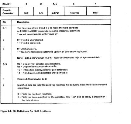
Read-State Transitions 3-21 Bit Defintions for Field Attributes 4-14
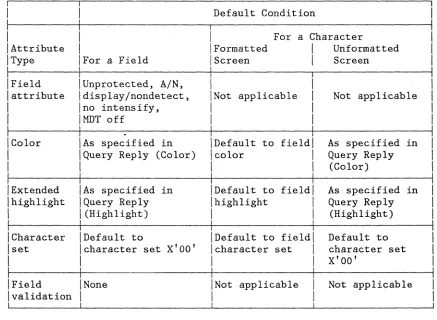
Attribute Default Conditions 4-30
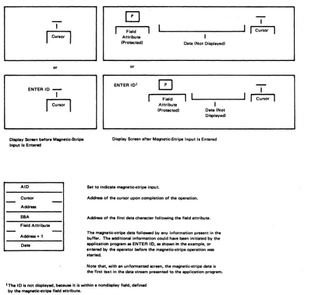
Display Screen Activity before and after Magnetic-Stripe Input (Unformatted Display) 5-3
Display Screen Activity before and after Magnetic-Stripe Input (Formatted Display with Unprotected Field Attribute) 5-4
5-3. 6-1. 6-2. 6-3. 7-1. 7-2. 7-3. 7-4. 7-5. 7-6. 8-1. 9-1. A-1. B-1. C-1. D-1.
Display Screen Activity before and after Magnetic-Stripe Input (Formatted Display with Protected Field Attribute) 5-5
The WCC Byte (As Defined for Use with Printers 6-2
The Copy Data Stream 6-10 Copy Control Character
(CCC) 6-10
Structured-Field Format 7-1 Vertical and Horizontal Slicing of a Character Cell 7-14
Type 1 Data Format--An Example Dot Pattern Encoded 7-15
E~ample of Compression
Algorithm Using Comparison Rule 1 7-18
Example of Compression Algorithm Using Comparison Rule 2 7-19
Example of Compression Algorithm Using Comparison Rule 3 7-20
Read-State Transitions for BSC 8-7
Read-State Transitions for Non-SNA Locally Attached Devices--3272 Version 9-6
SNA Sense Codes for 3270 Data Stream Errors (2 Parts) A-1
SNA Sense Codes for Structured-Field Errors
(3 Parts) B-1
(
CHAPTER 1. THE 3270 DATA STREAM: OVERVIEW AND CONCEPTS
INTRODUCTION
This chapter introduces the 3270 data stream, gives an overview of what it is and what it does, and discusses data stream concepts.
Not all 3270 data stream functions are implemented by all products using the 3270 data stream. You should therefore consult your product library for the 3270 data stream functions used by your products.
Chapters 1 through 6 describe the 3270 data stream in a systems network architecture (SNA) environment: Chapters 1 through 5 discuss the 3270 data stream for displays in the SNA environment; Chapter 6 covers printer applications. Chapters 8 and 9 describe the differences for binary synchronous communications (BSC) and non-SNA
locally-attached-device environments, respectively.
Note: Some environments may operate in a mixed mode, for example, BSC and synchronous data link control (SDLC); refer to the appropriate chapters to determine probable restrictions on using the 3270 data stream in this type of environment.
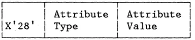
The 3270 data stream is a formatted data stream used for transmitting data between an application program and a terminal. The 3270 data stream supports both display and printer functions. The format is:
I
ILH
! TH RH 3270 Data Stream
I
£TI
I
. The LH, TH, RH, and LT are the link header, transmission header, request/response header, and link trailer, respectively.
OVERVIEW
The 3270 data stream is based upon the presence of a mapped character buffer in the device. There is a fixed one-to-one relationship between each character storage location in the buffer and each character
position on the display. For example, if a display has a display
0 80 160 240 320 400 480 560 640 720 800 880
80-Character-per-Line Display
79 159 239 319 399 479 559 639 719 799 879 959
o
2
959
. 960-Byte Character Buffer
Figure 1-1. Mapping the Display to the Character Buffer
The data stream allows the application program to divide the display surface into one active area and, optionally, one or more reference areas. Each area is called a partition, and the partition that is "active" is the one the operator is using to enter data or requests.
The application program uses partitions by first creating one or more partitions and then writing data to a specified partition. ·If the
application programmer chooses not to create partitions, then the entire display surface is the active area (and it is considered one partition).
The character buffer may contain codes for graphic characters or field attributes. Because each storage location in the character buffer is mapped to a screen position on the display surface, the field attribute takes up a character position on the display. The 3270 field attribute defines a field as that field attribute position plus the character positions up to, but not including, the next field attribute in the character buffer.
The data stream controls the processing and formatting of data with commands, orders, control characters, attributes, or structured fields. The command byte defines the function to be performed by the display.
DATA STREAM FORMAT
An application program sends data (and control instructions) to the display by means of commands. An outbound data stream is a data stream sent from the application program to the device, and contains:
Outbound Data Stream
The write control character (WCC) is used with write commands only.
An inbound data stream is sent from the device to the application
program and consists of an attention identifier (AID) followed by orders and data.
Inbound Data Stream
AID
Cursor Address (2 bytes)Data
In many cases the data is optional.
ATTENTION IDENTIFIERS (AIDS)
An AID, which is always the first byte of an inbound data stream, describes the action that caused the inbound data stream to be transmitted.
3270 DATA STREAM COMMANDS
Commands control such things as whether the application program writes to or reads from a display, and whether the screen is erased before new data is written. An application program sends data (and control
characters) to the display by means of commands. The commands and data used by the application program and display are as follows:
I
[Command
I
IWrite
I Erase/Write
IErase/Write Alternate IErase All Unprotected IRead Modified
IRead Modified All IRead Buffer
IWrite Structured Field I
Data after Command Can Include:
A WCC, orders and data A WCC, orders and data A WCC, orders and data None
None None None
Structured fields
3270 DATA STREAM ORDERS
Orders are instructions in the' 3270 data str'eam that provide control information. Theordars that can besant with
the
write commands are:•
Set Buffer Address (SBA)•
Start Field (SF)•
Start Field E'xtended (SFE)•
Modify Field eMF)•
Set Attribute (SA)•
Insert Cursor (IC)•
Program Tab (PT)•
Repeat to Address (RA)•
Erase Unprotected to Address (EUA)•
Graphic Escape (GE)The orders that can be included in the inbound data stream are:
• Set Buffer Address
• Start Field
• Start Field Extended
• Set Attribute
• Graphic Escape
3270 DATA STREAM ATTRIBUTES
Attributes determine the properties of a field or of characters within a field. The display uses three kinds of attributes: field attributes, extended field attributes, and character attributes.
DATA
STRUCTURED FIELDS IN THE 3270 DATA STREAM
Structured fields are used to convey additional control functions and data to or from the display. The Write Structured Field (WSF) command is used to transmit structured fields outbound.
The structured-field functions that can be accepted by a display are:
•
Create Partition•
Activate Partition•
Destroy Partition•
Set Window Origin•
Load Programmed Symbols•
Set Reply Mode•
Reset Partition•
Outbound 3270DSWrite
Erase/Write
Erase/Write Alternate
Erase All Unprotected
• Read Partition
Read Modified
Read Modified All
Read Buffer
Query
The display uses an AID
eX'88')
to indicate inbound structured fields. The structured field functions that can be sent by the display are:• Query Reply
The display shows data that has been transmitted to it from an
applieation progtam or. data that has been entered by the operator. The displayed data can be modified or deleted by the operator (or by further transmissions from the application program), and the revised data can be transmitted back to the application program for storage or additional processing.
Data received from the application program, or data to be transmitted to the application program, is stored in a character buffer and is
displayed on the screen in the form of alphanumeric characters and symbols. The displayed image is updated when the buffer data is modified by the operator and when new data is received from the application program.
UNFORMATTED AND FORMATTED SCREENS
An application program can use either a formatted or an unformatted Screen to communicate with a display operator:
• A formatted screen (fields defined by field attributes) is organized into fields by the application program.
• An unformatted screen (no fields defined) is regarded as one with a storage/display area that the operator uses in free-form manner.
The e~ample in Figure 1-2 illustrates the versatility of formatted
fields. In this example, the solid characters represent the displayed form of characters stored in the character buffer. The squares
represent buffer locations occupied by control characters called field attribute characters (which are actually displayed as blanks). The dotted characters represent a field of data that is stored in the buffer but has been defined by the program as nondisplayable - that is, not visible to the operator.
C]NAME
:[J
JOHN B DOE
,.., SA'
!'o. ~v r-, ,2
no. ,. zl..J ... /4i~ • L .. ~ ( .... .: ~~ •• ~
[] JOB TITLE :[],WRITER
[]PHONE
4f:{]383-·7628
KINDS OF ATTRIBUTES
Three kinds of attributes are used in the 3270 data stream: field attributes, extended field attributes, and character attributes. Field and extended field attributes define the start of a field and control the characteristics of the field. Character attributes control the characteristics of a character.
The field attribute occupies a character location in the character buffer and is stored in such a way that it is always displayed as a blank. The extended field attributes and character attributes do not occupy positions in the character buffer, but are nevertheless stored and do control the characteristics of the field and character(s), respectively.
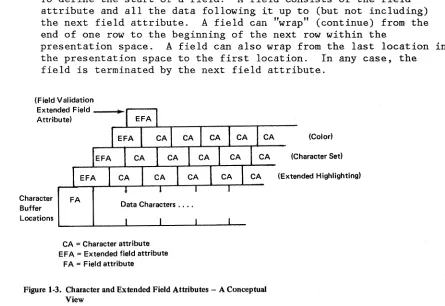
Conceptually, the extended field attributes are extensions of the field attribute, as shown in Figure 1-3.
Field Attributes
The field attribute is defined by the application program for the following purposes:
• To define the start of a field. A field consists of the field attribute and all the data following it up to (but not including) the next field attribute. A field can "wrap" (continue) from the end of one row to the beginning of the next row within the
presentation space. A field can also wrap from the last location in the presentation space to the first location. In any case, the field is terminated by the next field attribu~e.
(Field Validation
Extended Field _ _ ~ ... - - - . Attribute)
Character Buffer Locations
FA
Data Characters ....
CA = Character attribute EFA = Extended field attribute
FA = Field attribute
CA (Color)
CA (Character Sed
[image:18.612.94.539.398.704.2](Extended Highlighting)
There is no limit to the number of fields that can be defined, other than that imposed by the screen size.
To define the following characteristics for the entire field:
Protected or Unprotected. A protected field is protected from
modification by the operator. An unprotected field is available for the operator to enter or modify data. The unprotected definition classifies a field as an input field.
Alphanumeric or Numeric. Subject to its being unprotected, an alphanumeric field is one into which an operator enters data normally, using the shift keys (uppercase/lowercase or
numeric/alphabetic) as required.
Fields defined as numeric will accept all uppercase symbols and numerics from a data entry type keyboard. On a typewriter type keyboard, numeric has no meaning and all entries are accepted.
Autoskip. A field defined as protected and numeric causes the cursor to skip a subsequent field.
Nondisplay
£E
Display/Intensified Display. The selectedcharacteristics apply to the entire field. Nondisplay means that any characters entered from the keyboard are entered into the buffer for possible subsequent transmission to the application program but they are not displayed. Intensified display means the intensified characters appear on the screen brighter than the nonintensified characters.
Detectable or Nondetectable. A field defined as detectable can be detected by the selector pen or the cursor select key, subject to the use of a designator character
Base color (4 colors) can be produced on color displays and color printers from current 3270 application programs by use of combinations of the field intensify and field protection attribute bits. For more information on color, refer to the IBM 3270 Information System: Color and Programmed Symbols manual, GA33-3056.
Extended Field Attributes
The extended field attribute provides additional field definition beyond that provided by the field attribute. The extended field attribute defines field characteristics such as color, character set, field
validation, and extended highlighting. The extended field attribute is always associated with a field attribute. (See Figure 1-3.)
Attribute Pair -- Attribute Type Attribute Value
Attribute ~
Extended Highlighting
Color
Character set
Figure 1-4 (Part 1 of 2). Attribute Pairs
Attribute Value
Default. If used as a character attribute, the default is the characteristics defined by the extended field attribute. If used as an extended field attribute, the default becomes those characteristics indicated by the Query Reply (Highlight) structured field.
Underscore. Each character in the field is underlined.
Blink. Each character of field affected is caused to flash on and off.
Reverse video. In each character cell affected, the on/off illumination state of every display point .is reversed. The effect is analogous to white on black becoming black on white.
Default. If used as a character attribute it assumes the characteristics of the extended field attribute. If used as an extended field attribute, it is as indicated by the Query Reply (Color) structured field.
Multicolor. Indicates that the color is defined by a triple-plane Programmed Symbol set.
All others. Assigned to the color
identifications as indicated by the Query Reply (Color) structured field.
Default. If used as a character attribute, it assumes the characteristics of the extended field attribute. If used as an extended field attribute, it is the nonloadable character set that has the
tcrn
ofX'OO'
in the Query Reply(character sets) structured field.
Attribute ~
Field v,alidation
Figure 14 (Part 2 of 2). Attribute Pairs
Character Attributes
Attribute Value
Local character set ID. For the nonloadable character set.
Mandatory field. A field that must be modified by the operator before the operator can
transmit any data from the display.
Mandatory-fill field. A field that, if
modified by the operator, must be filled with characters other than the null character before the operator can move the cursor out of the field or transmit any data from the display.
Trigger field. A field that, if modified by the operator, is transmitted inbound as soon as the operator tries to move the cursor out of the field. This allows the application program to receive and to validate fields one by one.
A character attribute is associated with an individual character to define characteristics such as character color, character highlighting, or character set. The extended field attributes of any single character are superseded by the character attributes associated with it;
characters in nondisplay fields, however, are never displayed. The attribute structure used for character attributes is the same as for extended field attributes. (See Figure 1-4.)
THE CURSOR
The cursor is a special mark that is displayed on the screen to indicate where the next action from the keyboard will take effect (for example, where the next character keyed in will appear on the screen). One and only one cursor is displayed.
The cursor can be moved by the operator or by instructions from the application program.
PARTITIONING
Partitioning allows the application program to define a presentation space that may be different in both size and shape from the physical display surface. Multiple partitions can be defined for the display which will allow the display surface to be divided into several
rectangular areas called viewports, where data from multiple partitions may be displayed on the same physical display surface. The viewport is the area used to display and enter data for'that partition. (See Figure
1-5. )
The application program can organize a partition as either formatted or unformatted.
~
y
'"
"
... ...'" '"
"
...
"""""
" "
...'"
... ... ...,
'"
'"
"
Screen
...
...
"
"
...
Figute 1-5. Presentation Space and Viewport (without Scrolling)
Each partition has a unique partition identifier (PID) assigned at
creation time. The PID identifies the partition so that the application program can send data to, or receive data from, individual partitions.
Similarly, the .operato.r can enter, delete, or modify data in any selected partition (except in protected fields) by positioning the cursor appropriately within the partition's viewport.
If the application program does not define any partitions, the device assumes a single partition of default size with the PIO equal to O. This is referred to as the implicit partition.
READ FUNCTIONS FOR A PARTITION
The transmission of data from a partition can be initiated either by the application program or by the display operator the same as for a
nonpartitioned display surface. The display operator, however, can initiate a transmission only from an active partition. The application program can initiate a transmission from any partition by using the Read
Partition struct~red field. .
The Read Partition structured field provides the same read functions for partitions as the read commands do for nonpartitioned screens., for
example, Read Modified and Read Buffer.
EXPLICIT PARTITIONED AND HIPLICIT PARTITIONED STATES
The 3270 data stream supports displays in both explicit partitioned and implicit partitioned states. The initial state of a display supporting partitions is the implicit partitioned state (for example, power-on reset). The operation with implicit partition 0 on a display that supports partitioning is the same as on a display that does not support partitioning.
The application program can replace the implicitly created partition by explicitly creating one or more partitions of its own, thereby placing the display in explicit partitioned state.
CHAPTER 2. PARTITIONS
CREATING A PARTITION
The application program can define a "logical" screen. Galled a partition, which may differ in both size and shape from the physical display screen. The partition is defined by use of the Create Partition structured field. (Structured fields are discussed in Chapter 7.) Once a partition has been created, data is transmitted to and from the
partition as if it were a physical screen with the geometrical
characteristics specified in the Create Partition structured field. The mapping from the application program's view of the device to the
physical screen is transparent to the application program, once the partition has been successfully created.
CHARACTER BUFFER AND CONCEPT OF PRESENTATION SPACE
The amount of storage, in the character buffer, that is used by the partition is defined by the application program. Data in this buffer may be interacted with by the application program and by the operator. The character buffer provides storage for characters that may be
displayed on the display surface. This character buffer is simply addressable storage that contains as many locations as there are
character positions in the partition. Each buffer location contains one character and is separately addressable.
Conceptually, however, a partition can be regarded as a two-dim~nsional
presentation space whose size is defined in terms of its depth H (number of rows) and its width W (number of columns). Thus, the character
buffer associated with this partition is defined to be WxH bytes. The addresses of the character buffer locations range from 0 to (W x H) -1. The combination of viewport and associated presentation space is called a partition.
PRESENTATION SPACES, WINDOWS, AND VIEWPORTS
A partition has associated with it a conceptual two-dimensional surface, called the presentation space. Data may be thought of as being
Column 1
,
Row1_
--r--t----
Presentation SpaceRowH
t
_Column W
Figure 2·1. The Presentation Space-A Conceptual View
On the display surface, there is a rectangular area called a viewport. The viewport is that area on the display surface where the terminal operator sees the partition data displayed. Each viewport is related to a window so that the data in the presentation space within the window appears on the screenwith±n the viewport.
For processing 3270 data streams, a coordinate system must be defined on the presentation space. Rather than formatting data on the presentation space in row/column coordinates, 3270 compatibility :r'equires lineal addressing of the presentation space (also known as the character buffer) by use of the 3270 Set Buffer Address order. (Orders are discussed in Chapter 4.)
RELATIONSHIP BETWEEN PRESENTATION SPACE AND VIEWPORT
When the scrolling display function is not in use, a partition's
presentation s'pace and viewport have the same dimensions. (See Figure 1-5.) Assuming it is not in a "nondisplay" field, each data character in the presentation space is displayed in the corresponding row and column of the viewport.
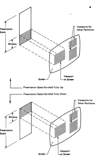
When the scrolling display function is in use, the viewport displays the data from a subarea of the presentation space caned the ,window. (See Figure 2-2.) The window and the viewport have the same dimensions (rows and columns). Assuming it is not in a nondisplay field, each data
character in the window is displayed in the corresponding row and column of the viewport. The position of the presentation. space data in
Presentation Space
4
Window'-
,
...
,
,
"
'-,
-...'-,
,
,
'- '-'-,
L
ScreenPresentation Space Scrolled Fully Up
Viewport on Screen
Presentation Space
V
,
"
,-...
,
'
"
,
Screen
[image:26.612.118.463.68.586.2]Viewport on Screen
Figure 2-2. Presentation Space, Window, and Viewport (with Scrolling)
•
Viewports for Other Partitions
SCROLLING
•
In a scrollable partition, the presentation space data can be moved up or down relative to the window by:
•
The operator using th~ SCROLL keys•
The application programWith this function, the application program positions the window by specifying the number of rows (see "Set Window Origin" in Chapter 7) by which the top of the window is to be offset from the top of the
presentation space.
THE CURSOR IN PARTITIONS
As on the nonpartitioned screen, the cursor can be moved by operator keystrokes or by instructions from the application program; but, always, the range of cursor movement on the screen is constrained to the bounds of a viewport. The cursor can be moved out of a given viewport only into another viewport; this can be accomplished by means of the
jump-partition key or an Activate Partitiqn structured field sent from the application program. The cursor can never appear at a screen position that is outside the bounds of a viewport. The partition associated with the viewport that contains the cursor is known as the active partition. The operator can enter data only into the active partition.
Associated with a partition is a current cursor position, which
determines where alphanumeric data is placed in the presentation space during operator keystroking. The cursor is displayed at the current cursor position of the partition. Data entry or cursor movement causes the current cursor position of the partition to be changed.
MULTIPLE PARTITIONS
The physical screen can be divided into several viewports, allowing data from multiple partitions to be displayed on the same physical screen. The partition with which the operator interacts is called the active partition, and only one partition may be active at a time; Each partition is identified by a partition ID (PID).
greater than N. If no such partition exists, the next active partition is that partition with the lowest PID.)
The application program may activate any partition by using the Activate Partition structured field, and may deactivate any partition by
activating another partition. (These structured fields are described in Chapter 7.)
THE IMPLICIT PARTITION
When the display is powered on, it is placed in implicit partitioned state. A single implicitly defined partition is created automatically and assigned a PID of 0 with the default screen size. In implicit partitioned state, the size of the implicit partition is controlled by the Erase/Write (EW) and Erase/Write Alternate (EWA) commands in the data stream.
EW redefines implicit partition 0 with the default screen size. EWA redefines implicit partition 0 with the alternate screen size. The default and the alternate size are specified in BIND SESSION.
The characteristics of the implicit partition are as follows:
• Partition parameters expressed in row/column coordinate system
• Partition size
=
Screen size• Window size = Partition size • Viewport size = Window size • Viewport origin
=
Screen origin• No scrolling permitted
• Unprotected (operator interaction allowed)
EXPLICIT PARTITIONS
The Create Partition structured field is used to replace the implicitly created partition 0 with a partition that is explicitly defined. The first Create Partition causes the implicit partition to be destroyed and the display to be placed in an explicit partitioned state.
partition 0 operates in implicit partitioned state, while explicit partition 0 operates in explicit partitioned state.
No matter which partition 0 is used, commands can be sent to the partition as the first byte of the data s,!:ream or enclosed in a structured field. When data is returned from either implicit or explicit partition 0, it is transmitted without use of the Inbound 3270DS structured field.
STATES AND STATE TRANSITIONS
Displays using the 3270 data stream can operate in one of two states. When operating without partitions (operating with implicit partition 0), the device is said to be in implicit partitioned state. When partitions have been created explicitly, with the Create Partition structured
field, the device is said to be in the explicit partitioned state. In each state, all the orders and commands described in this manual are valid. The distinction Qetween the two states relates to the way in which the usable area is managed. In implicit partitioned state, the size of the viewport equals the screen size. In explicit partitioned state, there can be more than one viewport on the usable area. For more information, see the Create Partition structured field in Chapter 7.
The presentation space (character buffer) controls the value at which buffer addresses wrap. In general, the presentation space may be equal to, or greater than, the viewport on the screen, with the window and the viewport always equal in horizontal and vertical dimensions. In
practice, for those devices that permit scrolling, the presentation space may be larger than the viewport. For devices that do not permit scrolling, the presentation space is of the same size as the viewport.
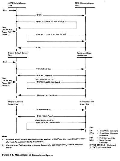
The management of presentation spaces is summarized in Figure 2-3. The commands, reset function, and structured fields shown in this figure are described in detail in the manual.
When in implicit partitioned state,EW establishes a default screen size and EWA establishes an alternate screen .size.
The functions of the EW, EWA, Write, and EAU commands on a partition with a nonzero PID are achieved by transmitting a WSF command containing an Outbound 3270DS structured field. This structured field contains the corresponding partition command; that is, it indicates whether the
3270 Default Screen Size
Bind ~I
3270 Alternate Screen Size
t==::::'",~OO'~'
' ..
"D~I
Clear ... _ _ _ _ _ _ _ _ _ _ _ _ _ _ _ _ _ _ _ _ _ _ ..1
CLEAR Key I
PowerOff~
(Note 11
,
C
dEWAI; d32700S Str Fld. PIO-OI"-1
... . . d E W I 4 -Display Default Screen
Size
Partitioned State
Screen Size
,,",~I
T
t----'''-" ...
- - - I ..~
I'"
dEW. WCC-Resed ClearCLEAR Ke_y~ r(32700S Str Fldl or Power Off - -
r
r(EW/EWA. WCC=No Resed(Note II ~
~!
, ... - - - r(Destroy Last p a r t i t i o n l - - - -....
t.
Display AlternateScreen Size
Partitioned State
Screen Size
N_:
1
.---
r(Creete Partitionl... _ _ _ _ _ dEWA. WCC=Re .. t l - - - -_ _ ... d32700S Str Fldl or
C
r(EW/EWA. WCC-No Re .. d·1
Key: EW EWA
Erase/Write command Era .. lWrite Alternate
command
1. Any loealaction, such 81 device return from loeal·telt or SSCP use, that resets thellCreen may
also reset the IICreen $ize to the default value.
PID =- Partition Identifier
[image:30.612.128.526.51.584.2]2. If a StfllCtur&d field cllllnot be processed. because of. dera stream error. no srats tTIIIIsitiOTl occurs.
Figure 2-3. Management of Presentation Spaces
WCC - Write Control Character 32700SSTR FLO = Outbound
INBOUND OPERATION (lNdP)
The d"splay recor~ inbound operation (INOP) so that it knows the oper tion to perform when it transmits data inbound. The display also
is received.
I \ ' ) set by any of the following:
• With the exception of a Read Partition structured field directed to partition 0,- whenever INPID is set to 0, INOP is set to Read
Modified.
•
•
•
An operator enter action, including a trigger action, sets INOP to Read Modified.
A Read Partition structured field sets INOP to the specified operation, namely, RB, RM, RMA, Query.
Acknowledgment of an inbound transmission sets INOP to Read Modified.
INBOUND PARTITION IDENTIFIER (INPID)
The display records the inbound partition identifier (INPID) so that it knows the partition to use when it transmits data inbound. The display also uses INPID to know which partition to use when an application program-initiated retry is received.
INPID is set by any of the following:
•
•
•
•
When an implicit partition is. created, INPID is set to
o.
An operator enter action, including a trigger action, setsINPID to the PID. of the active partition.
A Read Partition structured field sets INPID to the specified PID unless the PID is X'FF' (query operation), in which case INPID is unchanged.
• Acknowledgment of an inbound transmission sets INPID to O.
PARTITION WAIT CONDITION (PWAIT)
The partition-wait condition (PWAIT) is a partition-related
input-inhibit condition that, when raised, prevents operator keystroking into that partition. The following rules apply:
•
•
•
•
•
PWAIT is reset by the host; it cannot be reset by the operator.
While the PWAIT condition is raised for the active partition, an appropriate indicator is displayed.
At anyone time, only one partition can have a PWAIT condition (namely, the inbound partition, INPID).
PWAIT is used to prevent the operator from changing data after
performing an enter action, but before the host acknowledges receipt (for example, by keyboard restore).
Thus, PWAIT is caused by any operator enter action except a trigger action and is reset by the host's read acknowledgment.
THE SYSTEM LOCK CONDITION
System lock is a partition-related input-inhibit condition that, when raised, prevents operator keystroking into that partition_ The
following rules apply:
•
•
•
•
System lock can be reset by the host or by the operator.
While system lock is raised for the active partition, an appropriate indicator is displayed (provided a higher-priority condition, such as PWAIT, does not exist).
At anyone time, several partitions can have a system-lock condition.
System lock is raised, together with PWAIT, by any operator enter action except a trigger action.
System lock is removed by any of the following:
A RESET key pressed by the operator removes system lock from the active partition.
An end bracket (EB) indicator in the RU chain removes system lock from the inbound partition whose PID is defined by INPID.
THE -TERMINAL WAIT (TWAIT) CONDITION
TWAIT is a terminal-related input-inhibit condition that prevents the operator from keystroking. TWAIT is raised when there is only one
CHAPTER 3. 3270 DATA STREAM COMMANDS
INTRODUCTION
As described earlier, the 3270 data stream consists of commands, orders, control characters, attributes, data, and structured fields. This
chapter describes the commands and how they function in the data stream. The 3270 data stream commands and user-provided data are transmitted between the application program and the d~splay.
The outbound data stream usually consists of write commands and a WCC followed by orders and data. If the write command is a WSF, however, no WCC byte follows this write command in the data stream. The inbound data stream consists of an AID byte followed by data. The format of the write type command 'is as follows:
I
IWrite Command
I
WCC Orders and Data
or
i
IWSF Structured Field(s) !
COMMANDS
Commands are sent to a display to initiate the total or partial writing, reading, or erasing of data in a selected character buffer. Commands are sent as a command code in the first byte of a chain, or they may be sent in structured fields.
COMMANDS WITHIN STRUCTURED FIELDS
The Outbound 3270DS structured field provides the write-type command functions (Write, Erase/Write, Erase/Write Alternate, Erase All Unprotected), and the Read Partition structured field provides the read-type command functions (Read Buffer, Read Mod~fied, Read Modified All) .
In general, the command protocol is the same whether the function is initialized by a command code (first byte of the 3270 data stream) or by an Outbound 3270DS or Read Partition structured field. There are some
differences~ however, which are detailed in this chapter.
COMMAND CODES
The command codes are not unique code points and, therefore, rely on position to resolve ambiguity. Only one command is allowed per RU chain. The command must be the first byte of the 3270 data stream.
Following are the command codes and command abbreviations:
Command Abbreviation EBCDIC ASCII
Write W X'Fl' X'31'
Erase/Write EW X'FS' X'3S'
Erase/Write Alternate EWA X'7E' X'3D'
Read Buffer RB X'F2' X'32'
Read Modified RM X'F6' X'36' Read Modified All RMA X'6E' X'3E' Erase All Unprotected EAU X'6F' X'3F' Write Stru.ctured Field WSF X'F3' (Note)
Note: The use of structured fields requires that the full 8 bits of a byte be used; therefore,WSF is not supported in an ASCII environment.
THE WCC BYTE
The WCC is not a unique code, but is identified by position; that is, it is the byte following the write command. If the WCC is omitted,
whatever byte follows the write-type command is interpreted as the WCC. The data stream is normally a minimum of a W, EW, or EWA command and the WCC. If any write command (except EAU) is sent with no WCC or data, it
is treated as a no operation (no-op).
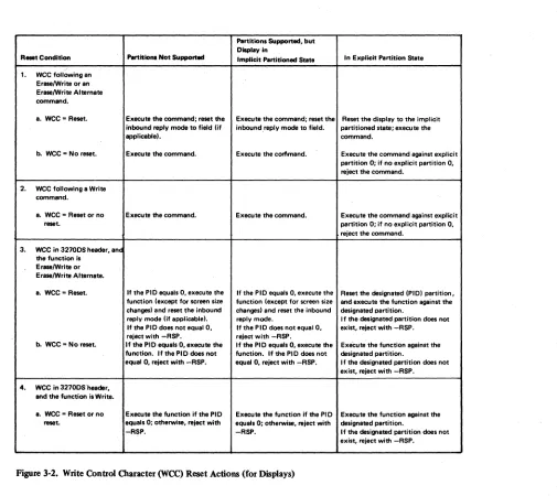
All WCC functions except for Reset MDT are deferred until data is written and orders are performed. See Figure 3-1 for a description of each WCC bit and Figure 3-2 for a summary of the reset actions.
When a data stream contains multiple WCCs (because of their appearance in structured fields), the WCC functions are executed as follows:
Reset--- Executed in each structured field as it is encountered.
Start print --- Executed at the end of the RU chain, after the write operation has been completed. Only the last
structured field may have a WCC that specified Start Print; otherwise, the chain is rejected
(sense code X'1001').
Sound alarm --- Executed for each structured field, at the end
of the operation specified for the structured field. Keyboard reset -- Executed for each structured field, at the end
of the operation specified for the structured field. Reset MDT --- Executed for each structured field, prior to the
writing of any data or the executing of any orders in the data stream.
Bit
o
2 and 3
4
5
6
7
Explanation
See Note.
WCC reset bit. When set to 1, resets partition characteristics to their system-defined defaults. When set to O. the current characteristics remain unchanged (no reset. operations are performed). See Note.
Reserved.
Start-printer bit. When set to 1. initiates a local-copy operation of the display surface at the completion of the write operation, When no printer is available, a
negative response (0801) is returned. (See Chapter 6 for details of local-copy operation.)
Sound-alarm bit. When set to 1, sounds the audible alarm at the end of the operation if that device has an audible alarm.
Keyboard·restore bit. When set to 1. restores operation of (unlocks) the keyboard .. I t also resets the AID byte.
Reset modified data tag (MDT) bits in field attributes. When set t01, all MDT bits in the device's existing character buffer are reset before any da~ is written or orders are executed.
[image:36.612.86.546.133.768.2]Note: If the reset function is not supported, the only function of bits 0 and t is to make the WCC byte an EBCDIC/ASCII-translatable character. Bits 0 and 1 are set in accordance with FigureD-,. If the reset function is supported, bit 1 controls reset/no reset and bit 0 has no function.· When bit 1 is used for the reset function, the WCC byte isno longer always EBCDIC/ASCII-trenslatable; the,.e-fore, the reset function cannot be supported in an ASCII environment
Partitions Supported. but Display in
R_Condition l'IIrtitiolll Not Supported Implicit Partitioned State In Explicit Partition State
/ 1. wee following an
Erase/Write or an EraselWrite Alternate command.
a. wee = Reset. Execute the command; reset the Execute the command; reset the Reset the display to the implicit inbound reply mode to fiald (if inbound,reply mode to field. partitioned stete; execute the
applicablel. command.
b. wee = No reMt. Execute the command. Execute the corflmand. Execute the command against explicit partition 0; if no explicit partition O. reject the command.
2. wee following a Write command.
a. wee -Reset or no Execute the commend. Execute the command. Execute the command against expliCit
raset. partition 0; if no explicit partition O.
reject the command. 3. wee In 32700S header. anc
the function I. EraselWrite or EraselWrite Alternate.
a. wee = Reset. If the PIO equals O. execute the If the PIO equals-O. execute the Reset the designated (PIOI partition. function (except for screen size function (except for screen size and execute the function against the changesl and reset the inbound chengesl and reset the inbound designated partition.
reply mode (;f applicablel. reply mode. I f the designated partition does not If the PIO does not equal O. If the PIO does not equal O. exist. reject with -RSP. reject with -RSP. reject with -RSP.
b. wee = No reset. If tha PIO equals O. execute the If the PIO equals O. execute the Execute the function against the function. If the PIO does not function. If the PIO does not designated partition.
equal O. reject with -RSP. equal O. reject with -RSP. I f the designated partition does not exist. reject with -RSP. 4. wee in 32700S'header.
and the function is Write.
8. wee = Reset or no Execute the function if the PIO Execute the function if the PIO Execute the function against the reset. aquals 0; otherwise. reject with equals 0; otherwise. reject with deSignated partition.
[image:37.612.61.566.49.499.2]-RSP. -RSP. If the designated partition does not exist. reject with -RSP.
WRITE OPERATIONS
The process of sending a write-type command and executing that command is called a write operation. Five write commands are initiated by the application program and executed by the display:
•
Write (W)•
Erase/Write (EW)•
Erase/Write Alternate (EWA)•
Write Structured Field (WSF)•
Erase All Unprotected (EAU)The first three commands are used by the application program to load, format, and selectively erase a character buffer or presentation space at the display. These commands can also initiate certain display operations, such as copying a display screen, restoring the keyboard, and sounding the audible alarm.
The Write Structured Field command sends structured fields to the display.
Write and Erase/Write operations are identical except that EW causes complete erasure of the character buffer before the write operation is started. Thus, EW is used to load the buffer with completely new data, whereas Write can be used to add t~ or modify existing buffer data. EWA
is identical with EW except that EW sets and uses the default display screen size while EWA sets and uses the alternate display screen size.
Write, EW, and EWA, when sent in the first byte of the data stream, are used for write operations in partition
o.
They must be encoded in a structured field if used for partitions with nonzero IDs.The WSF must be used for any write operation to partitions with nonzero IDs. The command is followed by one or more structured fields, which are interpreted and executed by the display. The structured field identifies the specific partition by its partition ID (PID).
WRITE COMMAND
The buffer location where data entry starts depends on the.starting location specified by the Set Buffer Address order that follows the
wee.
If an SBA does not follow thewee,
the starting location is the buffer address where the cursor is positioned.· The formatting and placement of write data and the modifying of existing buffer data·are described under "Orders" in Chapter 4.ERASE/WRITE COMMAND
Execution of the Erase/Write command performs the following functions:
1. Erases the character buffer by writing null characters into all buffer locations.
2. Sets all the associated character attributes to their default value
(X'OO').
3. Erases all field validation attributes.
4. Sets the current cursor position to 0. If directed to a partition, autoscro1-1 is performed if necessary to position the window at offset (0,0).
5. If bit 1 of the
wee
is set to bIll:a. Resets the inbound reply mode to Field.
b. Resets to implicit partitioned state. implicit partition PID to 0.
partitioned state, if currently in explicit It destroys all partitions, creates
°
with default screen size, and sets inbound6. Provides an acknowledgment of any outstanding read or enter if the keyboard-restore bit in the
wee
is set to bIll.7. Provides a negative trigger reply.
8. Performs a write operation.
Bit 1 in the
wee
carries reset information used by Erase/Write. If nowee
is defined following an Erase/Write, then no erasing or resetting occurs and it does not acknowledge any outstanding read or enter operation. However, it. is treated as a negative reply to a trigger field AID.ERASE/WRITE ALTERNATE CONNAND
This command performs the same operation as described for the
Erase/Write command, but it uses the alternate screen size. If there is no alternate screen size, the EWA is treated the same as an Erase/Write command.
WRITE STRUCTURED FIELD COMMAND
The WSF command is used to send structured fields from the application program to the display. On the application-to-display flow, structured fields can be sent only with the WSF command.
Devices not supporting structured-field data streams must reject this command (sense code X'1003').
The format of a Write Structured Field data stream is:
I
IWSF
I
Command Structured Field Structured Field
The data stream may contain one or more structured fields. Each structured field contains a length field that enables the receiver to calculate where the current field ends and the next one begins. Some structured fields may have a length field that equals 0, but only when sent as the last structured field in the RU chain.
The Outbound 3270DS is an example of a structured field. It allows one of four operations to be performed within the named partition:
•
Write•
Erase/write•
Erase/write alternate•
Erase all unprotectedERASE ALL UNPROTECTED (EAU) COMMAND
This command does the following:
• Clears all the unprotected character locations of the partition to nulls and resets any character attributes affected to their default values.
• Resets to 0 the MDT bit in the field attribute for each unprotected field.
• Unlocks the keyboard.
• Resets the AID.
• Repositions the cursor to the first character location in the first unprotected field of the partition's character buffer.
If the entire buffer is protected, buffer data is not cleared and MDT bits are not reset. However, the keyboard is unlocked, the AID is
reset, and the cursor is repositioned to the first buffer address in the partition.
READ OPERATION
The process of sending a read command and returning the requested information is called a read operation. A read operation can be
initiated by an explicit read command sent by the application program or by an operator action, for example, pressing the ENTER key. A read operation sends an inbound data stream to the application program with an AID byte as the first byte of the inbound data stream.
AID (ATTENTION IDENTIFICATION)
When the terminal operator initiates an enter operation, the display includes an AID byte in the input to the application program indicating the operator action. Operator actions that initiate an enter operation include:
•
Pressing a program-function or program-attention key.•
Pressing the ENTER, CLEAR, or Clear Partition key.•
Reading a magnetic stripe with a magnetic reader.•
Detecting on an attention field with the selector pen.The possible AID bytes are shown in Figure 3-3. All AID bytes
transmited by the display are a result of operator actions except for:
•
No AID generated•
No AID generated (printer)•
Structured field•
Read partitionThe display sends the no-AID-generated AIDs for unsolicited reads, errors, and unusual conditions. It sends the structured field AID whenever a structured field is sent inbound. The structured field may be sent as a result of some operator action, or it may be a reply to a previous application program request. It sends the Read Partition AID when replying to a Read Partition structured field requesting a read operation.
When data is transmitted to the application program, the most recent AID value is transmitted. The display records the most recent AID byte value. This value, initially set to no-AID-generated, may be set to another value by operator action. (See Figure 3-3.) The application program may reset the AID value to ~ AID generated by sending a write command with the keyboard-restore bit set on in the write control character.
Once the AID is set, it remains set and input is inhibited until one of the following commands is issued:
• Any write command that has the keyboard-restore bit on in the WCC
• Erase A1l Unprotected
READ COMMANDS
EBCDIC ASCII EBCDIC
AID (Ha) .. (Hex) (Graphic)
No AID genenited 6.0 20
No AID generated E8 59 y (printer only)
Structured field 881 h
Read partition 61 I Trigger action 7F
PF1 key F1 31 1
PF2 key F2 32 2
PF3 key F3