Malviya, Vihar, Mishra, Rakesh and Fieldhouse, John D.
Comparative computational analysis of dragreducing devices for tractortrailers
Original Citation
Malviya, Vihar, Mishra, Rakesh and Fieldhouse, John D. (2008) Comparative computational
analysis of dragreducing devices for tractortrailers. In: Proceedings of Computing and
Engineering Annual Researchers' Conference 2008: CEARC’08. University of Huddersfield,
Huddersfield, pp. 18. ISBN 9781862180673
This version is available at http://eprints.hud.ac.uk/id/eprint/3669/
The University Repository is a digital collection of the research output of the
University, available on Open Access. Copyright and Moral Rights for the items
on this site are retained by the individual author and/or other copyright owners.
Users may access full items free of charge; copies of full text items generally
can be reproduced, displayed or performed and given to third parties in any
format or medium for personal research or study, educational or notforprofit
purposes without prior permission or charge, provided:
•
The authors, title and full bibliographic details is credited in any copy;
•
A hyperlink and/or URL is included for the original metadata page; and
•
The content is not changed in any way.
For more information, including our policy and submission procedure, please
contact the Repository Team at: [email protected].
COMPARATIVE COMPUTATIONAL ANALYSIS OF DRAG-REDUCING
DEVICES FOR TRACTOR-TRAILERS
V. Malviya, R. Mishra, J. Fieldhouse.
University of Huddersfield, Queensgate, Huddersfield, HD1 3DH, United Kingdom.
ABSTRACT
Constant rise in fuel price in recent times has caused manufacturers of heavy commercial vehicles (HCV) to turn to efficient aerodynamic design of trucks, wagons, tractors as well as trailers.
The comparative analysis in this study compares the coefficient of drag of the following four aerodynamic configurations of a tractor-trailer combination:
1. Semi-trailer with no devices. 2. Semi-trailer with cab roof fairing.
3. Semi-trailer with the proposed rolling pin device.
4. Semi-trailer with the proposed rolling pin device and the cab roof fairing.
The overall coefficient of drag for the tractor-trailer combination for the above four configurations is computed and compared along with that of individual critical surfaces to analyse the effect of two major drag-reducing devices, the cab roof fairing and the momentum injection rolling pin. The pressure distribution in the flow field around the vehicle is studied to understand the flow mechanisms involved in the reduction in overall drag.
Keywords aerodynamic drag reduction, momentum injection, computational fluid dynamics
1. INTRODUCTION
Around 70% of all goods are transported by trucks and a large proportion of these are articulated tractor-trailers. Although the aerodynamic development of passenger and sports cars has seen much growth, the same cannot be said for commercial vehicles. Aerodynamic design of trucks and buses has seen some development only in the recent years after a stagnation of about thirty years (Modi 1997). This has been caused by continuously increasing fuel prices, which have forced the freight operators and hence truck, tractor and trailer manufacturers to explore the aerodynamic development of such vehicles.
The effect of aerodynamic drag force (FD) on a moving vehicle is proportional to the square of velocity (V).
FD = ½·ρ·CD·A·V2
Here, ρ is the density of air, CD is the coefficient of drag and A is the vehicle reference (frontal) area. The power (P) required to overcome this drag is proportional to the cube of the velocity (V).
P = ½·ρ·CD·A·V3
Hence at any speed above 30 mile/hour, aerodynamic drag is the most significant resistance force and up to 50% of the usable power of the engine is used to overcome this resistance. A typical large freight operator in the United Kingdom has approximately 600 tractor units and twice as many semi-trailers. Such a fleet would annually cover about 56 million miles, which translates to approximately £19.25 million in fuel (Department for Transport 2006). Hence, even a small fraction achieved in fuel savings could mean savings of thousands of pounds.
hence fuel consumption (Hammache et al. 2001; Browand 2005); this concept however requires a large scale collaborative effort and extensive logistics scheduling for harnessing significant benefit.
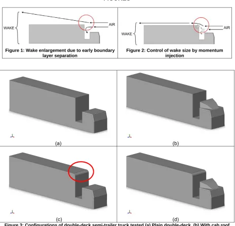
Pressure drag, which accounts for more than 90% of the aerodynamic drag (Browand 2005), is caused by the difference in pressure between the front and the wake of the vehicle. The air flowing around the vehicle causes separation of the boundary layer inducing a low pressure wake. As shown in Figure 1 boundary layer separation influences the size of the wake behind the vehicle due to its shape. Early separation significantly increases the pressure drag acting on the vehicle.
2. ROLLING PIN
Momentum injection or moving surface boundary-layer control (MSBC) is a concept which was initially intended for use on aircraft wings and airfoils for increasing lift and delaying the stall. The injection of kinetic energy into the flow over the top surface of the airfoil causes reduction in pressure over the top surface thus increasing lift, even at largely adverse angles. An example of MSBC in automotive aerodynamic research is the use of moving ground in automotive wind tunnels, which prevents formation of boundary layer near the ground and hence allows effective flow-field analysis under the vehicle. This concept is now being realised to reduce drag in bluff bodies and consequently being slowly adapted to embrace automotive aerodynamics. By injecting kinetic energy to the flow over the top surface of the vehicle the adverse pressure gradients can be reduce leading to delayed separation of the boundary layer. This causes reduction in the wake size (Figure 2) and hence in the pressure drag.
Delaying the separation minimises the relative motion between the surface and the free stream. This injection of momentum into an existing boundary layer also promotes higher velocities in its vicinity thus inhibiting development of high static pressure on the windward faces of the moving vehicle. This, coupled with the higher wake pressures significantly reduces the pressure drag. In case of tractor-trailer combinations, this device has also been found to improve the flow characteristics in the recirculation region (gap) between the tractor and the trailer (Singh et al. 2005) as shown in Figure 2.
The recirculation region of turbulent flow in the wake of a moving vehicle is also associated with periodic vortex shedding. Boundary layer suction and turbulence promoters have been studied and tested with various degrees of success (Munshi et al. 1999). Galloping of automotive vehicles is also a major stability concern which has been exhaustively researched on tall buildings, long bridges and similar bluff bodies. Momentum injection also serves as an alternative to using vibration suppression techniques like active mass damper and gyrostabilizers (Munshi et al. 1999). The delay in boundary layer separation by momentum injection serves this purpose by modifying the forces responsible for such vibrations.
The tractor-trailer geometry considered for this study was based on a generic tractor trailer combination 16.3m long, 2.6m wide and 4.7m high. The semi-trailer was 12.73m long. The rolling pin device considered in this study was mounted on the top leading edge of a semi-trailer, with its length same as the semi-trailer’s width. The diameter of the 0.7m was consistent with the ‘pin diameter / trailer length’ ratio used by Singh et al. (2005). For a reasonable basis for comparison with other drag-reducing devices, the vehicle (hence free stream) velocity (VAIR) in this study was taken as 19.5m/s (43.5 mile/hour, 70 km/hour). The linear velocity (VPIN) at the surface of the rotating pin was taken 3.9 m/s which is similar to the VPIN / VAIR ratio considered by Singh et al. (2005). This translates to an angular velocity (ωPIN) of 11.14rad/s (≈ 106 rev/min). The motive power required to rotate the rolling pin device can be provided by a standard DC motor which typically draws approximately 4 Amp of continuous current from the power system. As in most cases, if the vehicle power supply is assumed to be based on a 12 Volt system, the power required by the motor will be 48 Watt.
3. RESULTS AND DISCUSSION
million tetrahedral elements. Skewness of less than 0.6 was achieved for about 95% of the elements and an aspect ratio between 1 and 2 for about 99% of the elements. The lateral faces of the flow domain upstream and downstream of the tractor-trailer geometry were assigned the velocity inlet and pressure outlet boundary conditions; the inlet velocity was specified at 19.5m/s and the outlet pressure was defined at ambient atmospheric pressure. The bottom horizontal face of the flow domain was defined as a moving wall at 19.5m/s to simulate the motion of ground relative to the vehicle geometry. All other faces of the domain and the tractor-trailer were stationary walls. In case of the tractor-trailer with momentum injection, the curved face of the rolling pin was defined as rotating wall with an angular velocity of 11.14rad/s as computed section 2.The flow field in the meshed flow domain of the tractor-trailer was mathematically simulated the computational fluid dynamics (CFD) package Fluent (Fluent Inc. 2006); Fluent is used to iteratively solve Navier-Stokes equations along with the continuity equations and appropriate auxiliary equations depending on the type of application, using a control volume formulation. In this study the conservation equations for mass and momentum have been solved sequentially with two additional transport equations for steady turbulent flow. Linearisation of the governing equations is implicit. Computational simulation of each configuration was carried out on a two-node cluster of identical Windows-based workstations with a single 1.8GHz Intel Core 2 Duo processor and 2GB physical memory each. Each simulation lasted for about 4 hours before the residuals flattened out to their minimum values. A preliminary computational analysis of a single-deck tractor-trailer combination revealed that addition of a rounded leading edge to the semi-trailer improved the coefficient of drag of the base combination by about 9.5% from 0.77 to 0.70. This was done to ensure that the injection of momentum provided significant improvement in coefficient of drag compared to a stationary rounded edge.
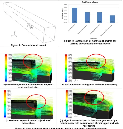
[image:4.595.86.533.467.787.2]As shown in Figure 5, it was found that the coefficient of drag was reduced by 16.38 % from 0.90 for a semi-trailer truck with no aerodynamic devices to 0.75 with the rolling pin installed on the leading edge of the semi-trailer. This improvement is comparable to that achieved by the tractor cab roof fairing. Further investigation using flow path visualisation (Figure 6) revealed that the flow path for the base tractor-trailer that diverges at the windward edge of the semi-trailer as shown in Figure 6(a). Although addition of the cab roof fairing improves the overall coefficient of drag by 16.32%, Figure 6(b) shows that the flow still diverges at the windward edge of the semi-trailer. The injection of momentum by the rolling pin significantly reduces this divergence of flow as shown in Figure 6(c). This is a direct consequence of the reduction in relative motion between the trailer surface and the flow. This reduction in flow divergence is further assisted by the inclusion of the cab roof fairing as shown in Figure 6(d); this is because the frontal area of the semi-trailer directly exposed to the flow is reduced.
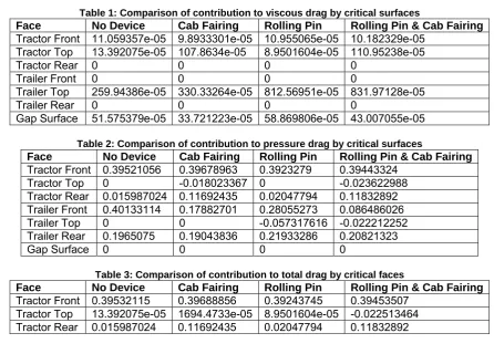
Table 1: Comparison of contribution to viscous drag by critical surfaces
Face No Device Cab Fairing Rolling Pin Rolling Pin & Cab Fairing
Tractor Front 11.059357e-05 9.8933301e-05 10.955065e-05 10.182329e-05 Tractor Top 13.392075e-05 107.8634e-05 8.9501604e-05 110.95238e-05
Tractor Rear 0 0 0 0
Trailer Front 0 0 0 0
Trailer Top 259.94386e-05 330.33264e-05 812.56951e-05 831.97128e-05
Trailer Rear 0 0 0 0
Gap Surface 51.575379e-05 33.721223e-05 58.869806e-05 43.007055e-05
Table 2: Comparison of contribution to pressure drag by critical surfaces
Face No Device Cab Fairing Rolling Pin Rolling Pin & Cab Fairing
Tractor Front 0.39521056 0.39678963 0.3923279 0.39443324 Tractor Top 0 -0.018023367 0 -0.023622988 Tractor Rear 0.015987024 0.11692435 0.02047794 0.11832892 Trailer Front 0.40133114 0.17882701 0.28055273 0.086486026 Trailer Top 0 0 -0.057317616 -0.022212252 Trailer Rear 0.1965075 0.19043836 0.21933286 0.20821323
Gap Surface 0 0 0 0
Table 3: Comparison of contribution to total drag by critical faces
Face No Device Cab Fairing Rolling Pin Rolling Pin & Cab Fairing
Trailer Front 0.40133114 0.17882701 0.28055273 0.086486026 Trailer Top 259.94386e-05 330.33264e-05 -0.049191921 -0.01389254 Trailer Rear 0.1965075 0.19043836 0.21933286 0.20821323 Gap Surface 51.575379e-05 33.721223e-05 58.869806e-05 43.007055e-05
Table 1 shows the contribution to viscous drag coefficient by listed surfaces considered critical when driving in a straight line in still air. Table 2 shows the contribution to pressure drag coefficient by the same surfaces. Similarly Table 3 itemises the total drag coefficient of each listed surface. It is clear from the individual values of drag coefficient, that although viscous drag contributes very little to total drag, the top surface of the trailer is major contributor to viscous drag due to skin friction with its large surface area. The injection of momentum marginally increases this coefficient from 260×10-5 to 812×10-5. This is far outweighed by the favourable pressure gradient caused by the injection of momentum shown in Table 2. The injection of momentum also dramatically reduces the pressure drag on the windward face of the semi-trailer with the cab roof fairing.
Figure 7 shows the static pressure distribution on the vertical lengthwise symmetry (X-Y) plane of the moving tractor-trailer combination. It shows predictably similar pressure distribution immediately upstream and downstream of the vehicle. Figure 7(a) shows a large region of high pressure on the windward side of the front face of the semi-trailer for the base tractor-trailer; this is significantly reduced in case of the tractor-trailer with the cab roof fairing as well as that with the rolling pin as shown in Figure 7(b) and Figure 7(c) respectively. Figure 7(d) shows a further reduced high-pressure region upstream of the semi-trailer. The illustrations also show that the cab roof fairing and the rolling pin are equally effective in reducing the low pressure region over the top surface of the semi-trailer immediately behind its top leading edge, hence effectively reducing the overall adverse pressure gradient in this region. However in case of the cab roof fairing a relatively high static pressure is observed at the bottom of the tractor-trailer gap; this can be attributed to the recirculation vortices created due to the increased area of the rear surface of the cab. Optimum design of the rolling pin can serve to reduce this high pressure created due to the recirculation vortices further improvement drag characteristics of the vehicle.
Figure 8 shows how the requirement of motive power varies with vehicle speed in still air on level road. A rolling resistance of 2795.85N is considered on the basis of a generic laden tractor-trailer weighing 38000kg (RoadTransport.com 2007). At about 25m/s (55mile/hour, 89km/hour) aerodynamic drag becomes the most dominant resistance force and the rolling pin provides a power saving of 9% from about 160kW to 145kW; when combined with the cab fairing it provides a further 6% reduction in power consumption down to about 135kW. At this speed 25kW reduction in power consumption translates to energy savings of about 455 Wh/mile. The energy density of diesel is 10.9kW/litre (Transtronics Inc. 2008); this translates to an improvement in fuel efficiency of 0.0417 litre/mile, which is about 7% of the average of 0.5747 litre/mile (2.8 km/litre) (Department for Transport 2006).
4. CONCLUSIONS
trailer, when optimised will provide a better insight into the true potential of the concept of momentum injection and its benefit in reducing aerodynamic drag.
REFERENCES
Browand, F., (2005). 'Reducing Aerodynamic Drag and Fuel Consumption'. [online] Available from: <http://gcep.stanford.edu/pdfs/ChEHeXOTnf3dHH5qjYRXMA/10_Browand_10_11_trans.pdf> [Accessed September 10, 2008].
Cole, L., (2008). 'Diesel prices and fuel tax'. RoadTransport.com. [online] Available from:
<http://www.roadtransport.com/Articles/2008/02/27/130000/diesel-prices-and-fuel-tax.html> [Accessed September 12, 2008].
Department for Transport, (2006). 'Smoothing the Flow at TNT Express and Somerfield using Truck Aerodynamic Styling'. Freight Best Practice. [online] Available from:
<http://www.freightbestpractice.org.uk/default.aspx?appid=1960&cid=42> [Accessed July 29, 2008].
DON-BUR, 'Aerodynamic Teardrop Trailer'. DON-BUR. [online] Available from:
<http://www.donbur.co.uk/gb/products/aerodynamic_teardrop_trailer.shtml> [Accessed September 11, 2008].
Fluent Inc., (2006). 'FLUENT 6.3 User's Guide'.
Fluent Inc., (2007). 'GAMBIT 2.4 User's Guide'.
Haegert, F.W., (1988). Aerodynamic structure for semi-trailer trucks. [online] Available from: <http://www.freepatentsonline.com/US4750772.html> [Accessed August 5, 2008].
Hammache, M. et al., (2001). Aerodynamic Forces on Truck Models, Including Two Trucks in Tandem, Berkeley (USA): University of California, Berkeley. [online] Available from:
<http://www.path.berkeley.edu/PATH/Publications/PDF/PRR/2001/PRR-2001-27.pdf> [Accessed September 11, 2008].
Hucho, W. ed., (1998). Aerodynamics of Road Vehicles 4th ed., Warrendale, PA (USA): Society of Automotive Engineers (SAE).
Matěj, S. & Jiří, N., (2004). 'Aerodynamic Devices to Reduce the Base- and Underbody Drag of Semitrailer Unit'. In: AED2004: sborník příspěvků 4th International Conference on Advanced Engineering Design na CD. Glasgow (UK): Orgit Ltd. [online] Available from:
<http://www3.fs.cvut.cz/web/fileadmin/documents/12241-BOZEK/publikace/2004/AED2004_Sulitka.pdf> [Accessed August 5, 2008].
McCullough, W., (2005). Aerodynamic guiding arrangements for vehicles. [online] Available from: <http://www.freepatentsonline.com/US6932419.html> [Accessed September 11, 2008].
Modi, V.J., (1997). 'Moving Surface Boundary-Layer Control: A Review'. Journal of Fluids and Structures, 11(6), pp.627-663. [online] Available from:
<http://www.sciencedirect.com/science/article/B6WJG-45KV1S5-C/2/2022cc2b7775d3e56a7d3af63ce478d6> [Accessed August 21, 2008].
Munshi, S.R. et al., (1999). 'Fluid dynamics of flat plates and rectangular prisms in the presence of moving surface boundary-layer control'. Journal of Wind Engineering and Industrial Aerodynamics, 79(1-2), pp.37-60. [online] Available from: <http://www.sciencedirect.com/science/article/B6V3M-3VCDJS3-3/2/9dbd10b96c9d8d8a54d47fd3fc504f6d> [Accessed September 4, 2008].
RoadTransport.com, (2007). 'Weights and dimensions / vehicle plating - 03/01/2007 - RoadTransport.com'. RoadTransport.com. [online] Available from:
Singh, S.N. et al., (2005). 'Effect of moving surface on the aerodynamic drag of road vehicles'. Proceedings of the Institution of Mechanical Engineers, Part D: Journal of Automobile Engineering, 219(2), pp.127-134. [online] Available from:
<http://journals.pepublishing.com/content/p00u8205t27983lh/> [Accessed July 24, 2008].
Sullivan, M.M., (2005). One piece A-pillar air deflector and windshield molding. [online] Available from: <http://www.freepatentsonline.com/US6899376.html> [Accessed September 11, 2008].
Transtronics Inc., (2008). 'Energy density'. Transtronics Home of Automation . [online] Available from: <http://wiki.xtronics.com/index.php/Energy_density> [Accessed September 12, 2008].
Wood, R.M., (2006). Cross flow vortex trap device and method for reducing the aerodynamic drag of ground vehicles. [online] Available from: <http://www.freepatentsonline.com/US6986544.html> [Accessed September 11, 2008].
FIGURES
Figure 1: Wake enlargement due to early boundary layer separation
Figure 2: Control of wake size by momentum injection
(a) (b)
[image:7.595.52.517.277.723.2](c) (d)
Figure 4: Computational domain
Figure 5: Comparison of coefficient of drag for various aerodynamic configurations
(a) Flow divergence at top windward edge for base tractor-trailer
(b) Sustained flow divergence with cab roof fairing
(c) Reduced separation with injection of momentum
(d) Significant reduction of flow divergence and gap recirculation with combination of rolling pin and cab
roof fairing
(a) High adverse pressure gradient for base tractor-trailer
(b) Reduced adverse pressure gradient with cab roof fairing
(c) Reduced adverse pressure gradient with momentum injection
[image:9.595.54.517.78.458.2](d) Highly reduced adverse pressure gradient with momentum injection and cab fairing Figure 7: Static pressure profile along the laterally symmetrical plane