2016 Joint International Conference on Artificial Intelligence and Computer Engineering (AICE 2016) and International Conference on Network and Communication Security (NCS 2016)
ISBN: 978-1-60595-362-5
Dynamic Simulation and Analysis of Free Piston Stirling Generator
with Shell Shock Absorption Mode
Ji-Gui ZHENG
1,2,a,*, Ping ZHENG
1,b, Chong XIAO
2,c,, Yu-Ping HUANG
2,d1School of Electrical Engineering and Automation, Harbin Institute of Technology,
Harbin, Heilongjiang, China
2Beijing Research Institute of Precise Mechatronic and Controls, Beijing, China
a[email protected], b[email protected], c[email protected], d[email protected]
*Corresponding author
Keywords: Terms--free Piston Stirling Generator, Dynamic Simulation, Characteristics.
Abstract: With a view to investigating the stiffness and external vibration disturbance of the free piston Stirling generator, a model of hot-machine-electric coupling system dynamics in shell vibration state is built in this paper for typical free piston Stirling power system, by theoretical analysis of thermodynamics and kinetics. Differential equations of hot-machine-electric coupling system are built, and the influence of stiffness and environmental excitation on dynamic performance and operational status of the system is also analyzed.
Introduction
Free piston Stirling generator is a highly efficient thermoelectric conversion system working with complex thermodynamic and kinetic coupling process, so the system is operating in a resonant state system of two degrees of freedom vibration. Since the displacement piston and power piston is connected without any physical mechanism, the pressure is transferred only by air. The system operates in a resonant state when the parameters are designed reasonable. It is a very complex task. Therefore, dynamic simulation model of free piston Stirling power system is the focus of many researchers’ work. And the model can be used for aided design and performance evaluation.
Since the 1960s, scholars have started analyzing the dynamic model of free piston Stirling power system. Power piston/displacement piston system is changed into spring-damper-mass system by Rauch [1]. With this change, the piston is supposed to move sinusoidal, and the amplitude and phase of the piston movement can be gotten from the solution of engine value equation.
Thermodynamics section of free piston Stirling engine power system is simplified to simple algebraic expressions, however, the differential equations are adopted by Chen and Griffin[2]. On this basis, all variables are supposed simple harmonic, and algebraic equations of piston amplitude and phase angle are gotten by linear analysis. State Space Method is adopted to analyze the Kinetic problem by Kankametal[3], and effect of stability caused by variation of the system parameters is studied.
SDM (Stirling Convertor System Dynamic Model), a simulation system of machine dynamics about freedom piston Stirling power, includes an initial heat input, piston motion, final power output etc., and interaction between the various subsystems is also considered[4,5,6]. In addition, the system can simulate thermal cycling, heat flow, the piston movement, a linear motor and a controller etc., and the time domain response of the system are given.
Free piston Stirling generator is supposed on completely fixed installation conditions in above researches, thus kinetic equation is basically a two-freedom model. Actually, stiffness and external vibration disturbance of freedom piston Stirling generator should be considered.
of stiffness and environmental excitation on dynamic performance and operational status of the system is also analyzed.
Power System Dynamics Analysis on Shell Shock Absorption Mode
Free piston Stirling engine and linear generator is coupled system, and the match is required for the stable operation of the system. Freedom piston Stirling generator controller is necessary for system operation.
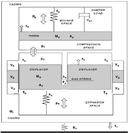
1-relief chamber 2-shell 3-Power piston connecting rod 4-spring 5-Linear motor secondary 6-Linear motor primary 7-power piston 8-cryogenic heat exchanger 9-regenerator 10-high temperature heat exchanger 11-displacer
[image:2.612.355.485.169.304.2]piston 12-inner cavity of displacer piston 13-expansion chamber 14-Pneumatic piston cylinder 15-spring 16-piston connecting rod 17-compression chamber 18-free piston stirling engine 19-Linear generator
Figure 1. Structural diagram of the free-piston Stirling generator.
Figure 2. Kinetic model schematic of freedom piston Stirling power system.
Fig. 2 shows the stress situation of freely piston Stirling power system components, and motion equations of general form are as follow:
( ) ( ) ( )( )
p p c b p p p c pc Hpc p c
M x P P A K x x C C x x . (1)
( ) ( ) ( ) ( )
D d D e c R c d d d c Hdc d c
M x A PP A PP K x x C x x . (2)
( ) ( ) ( )( ) ( ) ( )
C c D e b R c d pc Hpc p c p c p d c d C c
M x A P P A PP C C x x K x x K x x K x . (3)
Where Mp,MDandMC are the quality of power piston, displacement piston and power generation system shell, AP,AD andARare the cross-sectional area of power piston, displacement piston and displacement piston rod, Pe,Pc,Pb andPdare the gas pressure of expansion chamber, compression chamber, buffer chamber and displacement piston, Kp andKd are the stiffness of leaf spring between power piston and displacement piston, Cpc is electromagnetic damping, CHdc is the damping of gas spring in displacement piston, CHpc is the damping of gas spring in power piston and Kc is the equivalent spring stiffness between generator housing and installed base.
The isothermal model of Schmidt is adopted. Then Eq.1, 2 and 3 can be written as follow:
p pp p pd d pc c pp p pd d pc c
d dp p dd d dc c dp p dd d dc c
c cp p cd d cc c cp p cd d cc c
x S x S x S x D x D x D x
x S x S x S x D x D x D x
x S x S x S x D x D x D x
. (4)
Suppose:
exp[ ( )] , ,
i i i
x X j t i p d c. (5)
2
2
2
( ) ( ) ( ) 0
( ) ( ) ( ) 0
( ) ( ) ( ) 0
p d c p d c p d c j j j
pd pd d pp pp p pc pc c
j
j j
dd dd d dp dp p dc dc c
j
j j
cd cd d cp cp p cc cc c
S j D X e S j D X e S j D X e
S j D X e S j D X e S j D X e
S j D X e S j D X e S j D X e
. (6)
Then:
6 4 2 4 2
1 2 3 ( 1 2 3) 0
a a a j b b b
. (7)
Where ai and biare the function of coefficient in Eq.7. Make sure the real and imaginary parts are
zero, then and its constraints can be calculated. Take into Eq.7, let d 0, and , , ,
d d
p c
p c
X X X X
can
be calculated.
2 2 2 1 3 2
1
4 2
b b b b b
. (8)
Displacement piston, power piston and power generation system shell are supposed to be steady, and d 0 in Eq.5. Take the Eq.6 in matrix form:
2 2 2 0 d p c j d
dd dd dp dp dc dc
j
pd pd pp pp pc pc p
j
cd cd cp cp cc cc c
X e
S j D S j D S j D
S j D S j D S j D X e
S j D S j D S j D X e
. (9)
Suppose,
0
AX . (10)
To make sure the system of Eq.10 has a non-zero solution, the determinant should be zero,
0
A . (11)
ExpandA,
6 4 2 4 2
1 2 3 (1 2 3) 0
a a a j b b b
. (12)
Where ai and bi are the coefficient of function Eq.12.
The real part and imaginary part are equal to zero at the same time,
6 4 2
1 2 3 0
a a a
. (13)
4 2
1 2 3 0
b b b . (14)
When Eq.13 is constraint, can be calculated from Eq.14,
2 2 2 1 3 2
1 4 2
b b b b
b
. (15)
1 1 2 2 3 3 4 4 5 5 6 6
0 1 0 0 0 0
0 0 0 1 0 0
0 0 0 0 1 0
dd dd dp dp dc dc
pd pd pp pp pc pc
cd cd cp cp cc cc
x x
S D S D S D
x x
x x
S D S D S D
x x
x x
S D S D S D
x x
. (16)
Where,
1 d 2 d 3 p 4 p 5 c 6 c
x x x x x x x x x x x x . (17)
To ensure stable simple harmonic motion of linear system, eigenvalue of the zero real part should exist, and zero real root is single, and, meanwhile, the rest are negative real.
The Conditions of Single Zero Real Part
Assuming that the real part of characteristic root component is zero, zero real part of simple root is existent in Eq.16, and two real roots of Eq.14 should exist, which means discriminant of root
2
2 41 3 0
b b b
, 20.
To make sure:
2 0 , 2
1 0
b b
,b b1 30. (18)
Due tob1DddDppDcc,b1is less than zero. Therefore the constraint becomes
2 0
b ,b30. (19)
The Conditions of Negative Real Part Characteristic Root
The system is three degrees of freedom system. Therefore, the third order natural frequency exists, and linear differential Eq.16 has three characteristic roots, of which two real parts are zero. Then characteristic determinant matrix I B in Eq.16 is expanded,
6 5 4 3 2
1 2 3 4 5 6
I B c c c c c c
. (20)
Based on the known characteristic roots, i1and i2, hypothetical characteristic roosts, 5 and
6
, characteristic polynomialg
can be expressed by Eq. 212 2 2 2
1 2 5 6
( ) ( )( )( )( )
g . (21)
Expand theg
6 5 2 2 4
5 6 5 6 1 2
2 2 3 2 2 2 2 2
1 2 5 6 5 6 1 2 1 2
2 2 2 2
1 2 5 6 1 2 5 6
( ) ( ) [ ( )]
( )( ) [ ( ) ]
( )
g
. (22)
Contrast with Eq.20
2 2 5 6 c1 5 6 c6/ ( 1 2)
So,
2 2 2 2 2 2
1 1 6 1 2 1 1 6 1 2
5 6
4 / ( ) 4 / ( )
2 2
c c c c c c
. (24)
Due to c1 Ddd DppDcc, c1is positive and the rest three real parts are negative. Eq.20 and Eq.22 are equating coefficient.
2 2 2 2
1 5 6 2 5 6 1 2 3 1 2 5 6
2 2 2 2 2 2 2 2
4 5 6 1 2 1 2 5 1 2 5 6 6 1 2 5 6
( ) ( ) ( )( )
( ) ( )
c c c
c c c
. (25)
By Eq.25
2 2 2 2 2 2
1 2 3 1 1 2 5 1 5 6 2 1 2
2 2 2 2 2 2
5 6 4 1 2 1 2 5 6 6 1 2
/ / ( )
( ) / ( ) /
c c c c c
c c
. (26)
Thus, you can get two equations:
2 3 1 4 5 1 3 1
2 3 1 6 5 1
/ ( / ) / ( / )
/ / ( / )
c c c c c c c c c c c c c c
. (27)
Therefore, to satisfy the Eq.14, Eq.27 must be satisfied. In summary, conditions of linear steady state are 2
2 4 1 3 0
b b b
, b 20 andb30.
2 3/ 1 ( 4 5/ ) / ( / )1 3 1 2 3/ 1 6/ ( / )5 1
c c c c c c c c c c c c c c . (28)
Analysis of Stiffness
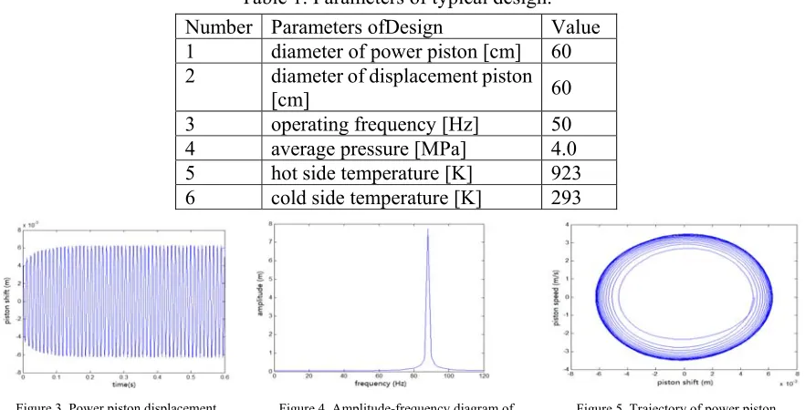
[image:5.612.89.530.484.709.2]The responses of the system under different connection stiffness are calculated to analyze the relationship between stiffness and response of thermal-Mechanical-Electrical system (The typical parameters of the system are shown in Table 1), Fig.3-11 shows the results.
Table 1. Parameters of typical design.
Number Parameters ofDesign Value
1 diameter of power piston [cm] 60 2 diameter of displacement piston
[cm] 60
3 operating frequency [Hz] 50
4 average pressure [MPa] 4.0
5 hot side temperature [K] 923
6 cold side temperature [K] 293
Figure 3. Power piston displacement response at Kc=10e7.
Figure 4. Amplitude-frequency diagram of power piston displacement response at Kc=10e7.
Figure 6. Power piston displacement response at Kc=10e6.
Figure 7. Amplitude-frequency diagram of power piston displacement response at Kc=10e6.
Figure 8. Trajectory of power piston at Kc=10e7.
Figure 9. Power piston displacement response at Kc=10e5.
Figure 10. Amplitude-frequency diagram of power piston displacement response at Kc=10e5.
Figure 11. Trajectory of power piston at Kc=10e5.
Fig.3 and Fig.11 show that when the foundation stiffness Kc=10e7, power piston is in a stable single-frequency harmonic motion state. When the foundation stiffness is strong, its amplitude of movement and frequency are less affected by the foundation stiffness. With the base stiffness getting lower, when the foundation stiffness is Kc=10e6 or Kc=10e5, new frequency components bring out in power piston motion response, and the magnitude of the movement also has some volatility. Therefore, when the foundation stiffness is greater, the system is more stable.
The Influence of External Environment Excitation to Thermal Mechanical-electric-coupling System Response
The influence of external environment excitation on thermal mechanical-electric-coupling system response is discussed in this section. Table 1 shows the plan, and response of power system is calculated. The basic stiffness of power system Kc=10e7, and amplitude of External harmonic excitation force is 0.0011m, and frequency is 50Hz. Fig.12-13 show the calculation results.
Fig.13 shows the influence of displacement response of power piston when external harmonic excitation force works. There are two frequency components in the displacement response of power piston, which are self-excited vibration frequency of power system and outside harmonic excitation force frequency.
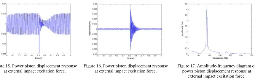
Table 1 shows the plan and the response of power system when typical impact excitation works. The excitation force is supposed to be rectangular pulse load, which the amplitude of is 200m/s2 and lasts 10ms. When t=5s, the basic impact load works, and response to the external load disturbance is calculated. Fig.14-16 show the calculation results.
Figure 12. Power piston displacement response
at 50Hz external excitation force. ofpower piston displacement response at 50Hz Figure 13. Amplitude-frequency diagram external excitation force.
Figure 15. Power piston displacement response at external impact excitation force.
Figure 16. Power piston displacement response at external impact excitation force.
Figure 17. Amplitude-frequency diagram of power piston displacement response at
external impact excitation force.
Fig.14-16 show that, power piston, displacement of the piston and movement of the housing are disturbed when power system suffered to basic impact load. Amplitude of three displacements has greatly increased to an instant impact, with response of system gradually returning to normal in about 0.2s-0.3s. Fig.17 shows that self-excited oscillation frequency is the main component of power piston displacement frequency response, and other frequency components exist due to external impact load.
Summary
The paper shows that freedom piston Stirling generator is a resonant system, so it's stiffness of fitting seat have a greater impact on the system stability. Power piston is in a stable single-frequency harmonic motion state when the foundation stiffness is strong, whose amplitude of movement and frequency is less affected by the foundation stiffness. However, with the base stiffness getting lower, new frequency components bring out in power piston motion response, and the magnitude of the movement also has some volatility. Therefore, when the foundation stiffness is greater, the system is more stable.
In addition considering the foundation stiffness, when external harmonic excitation force works, displacement response of piston power generation system is also impacted to a certain extent. Self-excited oscillation frequency is the main component of power piston displacement frequency response, and other frequency components exist due to external impact load.
Acknowledgement
The work is supported by School of Electrical Engineering and Automation, Harbin Institute of Technology Lab. The authors would also to thank Yu-ping huang, for his valuable technical support with the typical parameters of the system. This research was financially supported by National Natural Science Foundation of China (Grant No. 50877013).
References
[1] Rauch, J.S. “Steady-State analysis of free-piston stirling engine dynamics,” IECEC, 1975. pp. 961-965.
[2] Chen, N. C.J., Griffin, F.P. “Linear harmonic analysis of free-piston stirling engines,” ORNL/CON-172. Martin Marietta Energy Systems, Inc., Oak Ridge Natl. Lab.
[3] Kankam, M.D., Rauch, J.S., Santiago, W. “Dynamic analysis of free-piston stirling engine/linear alternator-load system-experimentally validated,” SAE Technical Papers, 1992.
[5] Lewandowski, E.J., Regan, T.F. “Overview of the GRC stirling convertor system dynamic model,” Proceedings of the Second International Energy Conversion Conference (IECEC 2004), August 2004. pp. 1252-1264, Vol. 2.