EXPERIMENTAL STUDY OF UNSTEADY HYDRODYNAMIC FORCE MATRICES ON WHIRLING CENTRIFUGAL PUMP IMPELLERS
Thesis by Belgacem Jery
Division of Engineering and Applied Science
In partial fulfillment
of the Requirements for the Degree of Doctor of Philosophy
California Institute of Technology Pasadena, California
1987
-ii-ACKNOWLEDGEMENTS
I would like to express my deepest thanks to my advisors, Professors Christopher Brennen,
Allan Acosta and Thomas Caughey. Not only did they provide me with the best technical
assistance but they also expressed friendship and genuine concern for my welfare during the
years of my education.
The help of several other people was instrumental in the success of various phases of this
experimental work. I am particularly indebted to Dr. Haskell Shapiro from Shapiro Scientific
Instruments, Corona Del Mar, California, for his assistance in the design of various electronic
systems. Among the personnel of the lnstitute's Central Engineering Services my thanks go to N.
Keidel, L. Johnson, G. Yamamota and M. Gerten for their expert help with the design and construction of most of the mechanical components. Thanks also to G. Lundgren from the
Aeronautics shop for directing the delicate task of machining the rotating dynamometer. Just as
delicate was the task of instrumenting this dynamometer, which was successfully carried out by J.
Hall from Microengineering II, Upland, CA. Thanks for many years of reliable operation.
Thousands of hours were spent preparing the test rig and collecting data from the various
experiments. Many of these hours were contributed by student colleagues and friends D. Adkins,
R. Franz, N. Arndt, W. Goda, D. Brennen, S. Moriarty, M. Karyeaclis and P. Chen. I very much
appreciated their efforts. The help of C. Lin with the graphics and S. Berkeley with the
administrative tasks was also greatly appreciated.
It takes substantial financial support to bring to term an experimental project of this magnitude.
This support was generously provided by NASA's George C. Marshall Space Flight Center,
Huntsville, Alabama. My advisors and I are very thankful for it. Rocketdyne Division of Rockwell
International, Canoga Park, CA, provided a diffuser volute and half an SSME's HPOTP's double
suction impeller for testing. Byron-Jackson Pumps Division of Borg-Warner Industrial Products
-iii-My personal financial needs were met through a grant from the Foundation ENSAM, a
scholarship from the Scientific Mission of Tunisia, a Graduate Research Assistantship from the
California lstitute of Technology and a Research Fellowship from Byron-Jackson Pumps Division. I
am forever indebted to all these sources.
Some contributions are hard to describe with words, let alone quantifiy. These came from my
family and close friends whose love, patience and encouragement meant so much to me. I say:
thank you all for being there when I needed you most.
This thesis is dedicated to my mother and father Fatma and Ammar, who never had a chance
-iv-ABSTRA.CT
An experimental facility was constructed and instrumented. A study was conducted on a set
of centrifugal flow pumps whose impellers were made to follow a controlled circular whirl motion.
The aim was to characterize the steady and unsteady fluid forces measured on the impeller under
various pump operating conditions. The postulation was that the unsteady lateral forces result
from interactions between the impeller and the surrounding diffuser and or volute (via the working
fluid), and that under certain flow regimes these forces can drive unstable lateral motions of the
pump rotor.
The lateral hydrodynamic forces were decomposed into their steady and unsteady parts, the
latter being further expressed in terms of a generalized fluid stiffness matrix. A study of this matrix
as a function of the whirl to pump speed ratio supported the following chief conclusions:
i) the common assumption of matrix skew-symmetry is justified;
ii) the magnitudes and signs of the matrix elements are such that rotor whirl can indeed be caused by the hydrodynamic forces, in pumps operated well above their first critical speed,
iii) as expected, the matrix is very sensitive to the value of the flow coefficient, especially at flow rates below the design;
iv) the commonly postulated quadratic variation of the matrix elements with the reduced whirl
frequency, resulting in the so-called rotordynamic coefficients (stiffness, damping and inertia)
is not justified for flow coefficients significantly below design; and
v) surprisingly, it was discovered that the presence, number and orientation of diffuser guide
vanes have little effect on the forces.
Conclusions regarding the effect of impeller geometry could not be reached given the
similarity.of the tested designs. However, other results on phenomena such as skin friction and
leakage flow are presented. Some of the findings are compared to experimental and theoretical
data from other sources. Finally, the rotordynamic consequences of the results are discussed as
the present data were applied by another author to the case of the Space Shuttle Main Engine's
-v-TABLE OF CONTENTS
Page
ACKNOWLEDGEMENTS
i i
ABSTRACT
iv
TABLE OF CONTENTS
v
LIST OF SYMBOLS
viii
LIST OF FIGURES
x
1. INTRODUCTION 1
1.1 Presentation of the Problem 1
1.2 Terminology of Rotor Whirl 2
1.3 Cases of Rotordynamic Instabilities 8
1.4 Survey of Current Knowledge 11
1.5 Scope and Goals of Present Research 21
2.
EXPERIMENTAL FACILITY 272.1 The Dynamic Pump Test Facility 27
2.2 The Rotor Force Test Facility 28
2.3 The Eccentric Drive Mechanism 30
2.4 Housing, Volutes and Impellers 31
2.5 Auxiliary Pump 33
2.6 System Controls 33
2. 7 Instrumentation 35
3. ROTATING DVNAMOMETER 55
3.1 Introduction and Basic Design Features 55
3.2 Fabrication 57
3.4 Dynamic Characteristics
4. MATRIX OF EXPERIMENTS
4.1 Test Hardware and Variables
4.2 Preliminary Measurements
4.3 Fluid Force Measurements
4.4 Auxiliary Measurements
-vi-5. DATA ACQUISITION AND REDUCTION TECHNIQUES
5.1 Signal Conditioning
5.2 Data Acquisition and Storage
5.3 Data Reduction Technique and Software
5.4 Measurement Errors
6. RESULTS AND DISCUSSION
6.1 Preliminary Results
6.2 Unsteady Force Measurement Results
6.2.1 Generalized Hydrodynamic Stiffness Matrix
6.2.2 Effect of Flow Coefficient
6.2.3 Effect of Volute and Impeller Design
6.3 Additional Test Results
6.4 Rotordynamic Matrices
6.5 Comparison With Results From Other Sources
6.6 Discussion
7. SUMMARY AND CONCLUSIONS
APPENDIXB
APPENDIXC
APPENDIX D
-vii-154
161
a
[A]
[C]
c
-viii-LIST OF SYMBOLS
= side dimension of square cross sectional area of dynamometer's post
= impeller discharge width
= dimensionless hydrodynamic force matrix
= hydrodynamic damping matrix as defined by Eq. (1.8)
= impeller face seal clearance, also volute ring clearance
= generalized six-component force vector
= components of instantaneous lateral force on impeller in the rotating
dynamometer reference frame (1,2)
= components of instantaneous lateral force on impeller in fixed laboratory
reference frame (X,Y) non-dimensionalized by p7tr23m2b2
= values of Fx and Fy when impeller axis remains coincident with the origin of the
(X,Y) coordinate system
= components of lateral force on impeller normal to and tangential to the whirl orbit,
non-dimensionalized by p7tr23m2b2e and averaged over one whirl orbit
I, J = integers such that !l=lm!J
[K] =hydrodynamic stiffness matrix as defined by Eq. (1.8) [M] = hyrodynamic inertia matrix as defined by Eq. (1.8)
N =pump rpm= 60m/27t
r2 = impeller discharge radius
x,y
x, y,x,y
(X,Y)
=time
=instantaneous coordinates of impeller center in fixed laboratory reference frame,
(X,Y), non-dimensionalized by r2
= first and second time derivatives of impeller position non-dimensionalized using
Impeller X's radius, r2, and the time m-1
p
<I>
qs
= radius of circular whirl orbit
= density of water
-ix-= pump flow coefficient based on impeller discharge area and tip speed
=
pump total head coefficient=
total head rise /pr22ro2=
radian frequency of pump shaft rotation=
2IIN/60-x-LIST OF FIGURES
Fig.1 .1 Idealized case of rotor whirl due to pure mass unbalance of a weightless vertical shaft. Top: without damping. Bottom: with damping.
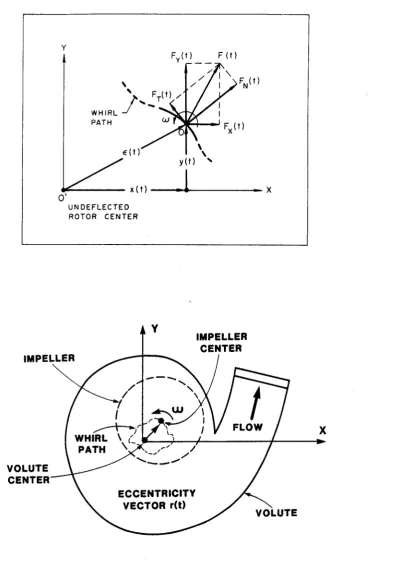
Fig. 1.2 Top: diagram of the in-plane forces acting on a whirling impeller at its center, 0. Bottom: schematic of a centrifugal pump whith a whirling impeller, ro = pump speed (rad/sec).
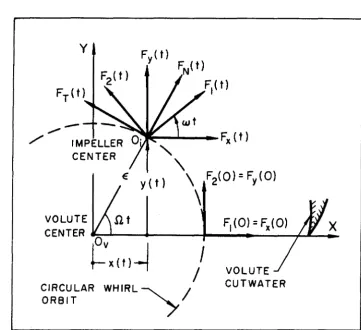
Fig. 1.3 Circular whirl for a centrifugal flow pump. Fx and Fy are the impeller forces in the laboratory reference frame, (X,Y), where the X-axis is the line joining volute center to volute tongue. F1 and F2 are the lateral impeller forces sensed in the rotating frame of the impeller, (1,2). FN and Fr are the normal and tangential (to the circular whirl orbit) components of the impeller lateral forces.
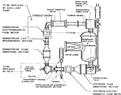
Fig. 2.1 Schematic top view of the Dynamic Pump Test Facility (DPTF), before the addition of the Rotor Force Test Facility (RFTF) at bottom left corner, and the auxiliary pump at the top left corner.
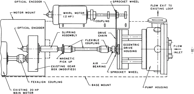
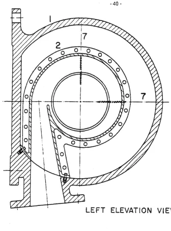
Fig. 2.2 Schematic layout of the main components of the Rotor Force Test Facility (RFTF). Fig. 2.3 Left: left elevation view of the Rotor Force Test Facility (RFTF) test section.
Right: plan view of RFTF test section showing pump casing, 1, volute, 2, inlet section, 3, inlet bell, 4, impeller, 5, rotating dynamometer, 6, proximity probes, 7, eccentric drive outer and inner bearing cartridges, 8 and 9, shaft, 10, sprocket wheel, 11, outer and inner bearing sets, 12 and 13, flexible bellow, 14, impeller front and back face seals, 15 and 16, inner and outer bearing seals, 17 and 18, strain gage cable connector, 19, flexible coupling 20, and air bearing stator, 21.
Fig. 2.4 A table summary of the characteristics of the various "impellers" tested. Only Impeller X and Impeller Y are true impellers.
Fig. 2.5 A table summary of the characteristics of the various volutes tested. Volutes D, F, G and H differ only by the number and arrangement of diffuser guide vanes. Tongue angle is the angle between the upward vertical and the line joining volute center to volute tongue. Vane sector is the angle subtended by the vane.
Fig. 2.6 Graphic summary of the cross-sectional geometries of the various volute designs tested.
Fig. 2.7 Isometric sketch of auxiliary pump and associated piping and valves. This pump is used to circulate water in the loop in either direction allowing four quadrant operation of the main test pump.
Fig. 2.8 Diagram of the Rotor Force Test Facility (RFTF)'s system controls (siren valve
fluctuators were not used in the present experiments). Integers I and J are input by the operator to set the ratio of whirl-to-pump speed: ro=ln/J.
-xi-Fig. 2.10 Photograph of current Dynamic Pump Test Facility, including the RFTF's test section (right side) and auxiliary pump (foreground, left).
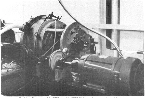
Fig. 2.11 Photograph of the RFTF part of the DPTF. Visible are the pump casing and discharge section, the eccentric drive motor and transmission (the picture was taken after the chain was replaced by a belt). The flexible coupling in the main shaft assembly is removed and the slip-ring side of the dynamometer cable can be seen in the far right. Fig. 2.12 Photograph of the test pump as viewed from the inlet side, with the casing cover
bolted in place.
Fig. 2.13 Photograph of the test pump. The casing cover is removed, showing Impeller X seated inside Rocketdyne Diffuser Volute E.
Fig. 2.14 Photographs of the various "impellers" tested. From top left: Byron-Jackson five-bladed Impeller X, Byron-Jackson six-five-bladed Impeller Y, solid dummy impeller, Impeller S, duplicating the outside geometry of Impeller X, and thin cirular disc, Impeller K.
Fig. 2.15 Photographs of the various volutes tested. From top left: Volute A, Volute B, Volute C, Diffuser Volute H, Diffuser Volute G, and Rocketdyne Diffuser Volute E.
Fig. 3.1 Top: schematic of rotating dynamometer's basic four-post configuration showing strain gage location and generalized force sign conventions. Bottom: assembly drawing of rotating dynamometer with protecting sleeve, impeller mounting mandrel, and various o-rings used to seal dynamometer cavity.
Fig. 3.2 Top: typical in-situ static calibration loading graphs. Bridge #1 is primarily sensitive to loading in the F1 direction. Bottom: typical response of same bridge to a hysteresis loading cycle in primary direction.
Fig. 3.3 The weight of Impeller X is sensed as a rotating force vector in the frame of the dynamo meter (F1 ,F2), when the shaft is rotating. Plotted are: magnitude of gravity vector (top) and phase angle (bottom, referenced to upward vertical), for various shaft rotational speeds in air (up to 3000 rpm).
Fig. 3.4 Top: spectral response of the installed impeller-dynamometer-shaft-eccentric-drive system after a lateral impulse (hammer shock) is applied to the impeller. System damped natural frequency is shown to be near 160 Hz. Bottom: typical spectral analysis of bridge output signal recorded during shaft rotation in air at 800 rpm. Synchronous response is at 13 Hz (peak at -17 Db).
Fig. 3.5 Photograph of the eccentric drive disassembled from the Rotor Force Test Facility. Visible are (from left to right) the sprocket wheel, the main double bearing housing, a dummy replacing the actual dynamometer, and Impeller X mounted at the end of the drive shaft.
Fig. 3.6 Photographs of the rotoating dynamometer with (top), and without (bottom) its protecting sleeve.
Fig. 3.7 Photograph of a typical arrangement of the static calibration rig, employing loading plate, brackets, pulleys, cable and weights. Arrangement shown is for loading in the positive F1 direction (upward vertical in laboratory frame).
-xii-Fig. 4.2 Evolution with the reduced whirl frequency of the normal (top) and tangential (bottom) components of the orbit-averaged lateral force sensed by the dynamometer during simultaneous whirl and concentric motions of Impeller X in air, for various shaft speeds (500 to 3000 rpm).
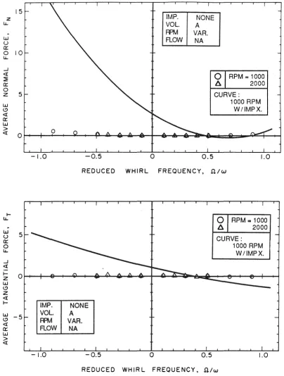
Fig. 4.3 Evolution with the reduced whirl frequency of the normal (top) and tangential (bottom) components of the orbit-averaged lateral parasitic hydrodynamic force sensed by the dynamometer during simultaneous whirl and concentric motions of the submerged pump shaft (in the absence of an impeller), for two pump speeds (circles:1000 rpm, triangles: 2000 rpm). Comparison is made with the corresponding components of the actual impeller-induced hydrodynamic force (curve: Volute A, Impeller X at design flow and 1000 rpm).
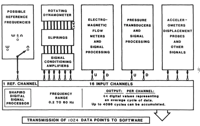
Fig. 4.1 Flow chart of signal processing. The Shapiro Digital Signal Processor is a Motorola 68000-based microprocessor. The reference signal is synchronized with the motions (concentric and eccentric) of the rotor. The 16 input channels are sampled sequentially, and readings are cumulated and averaged over several reference cycles. A maximum of 1024 average digital values (16 channels x 64 data points per channel) are stored in each run and then transmitted to the Zenith Z-120 desktop computer for further processing.
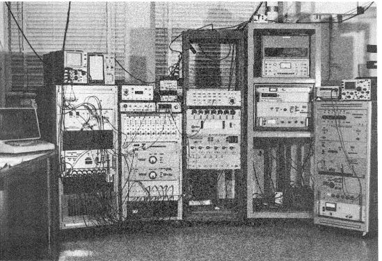
Fig. 4.2 Photograph of the instrumentation racks. Visible are, in particular, the Zenith Z-120 computer (far left), the Shapiro Digital Signal Processor (middle of leftmost rack), a battery of1 O signal conditioning amplifiers (top of second rack), and the servo-controls for whirl and pump motors (bottom of second rack).
'
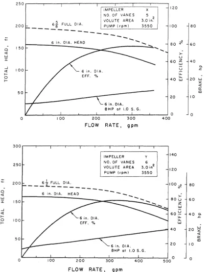
Fig. 6.1 Manufacturer supplied dimensional hydraulic performance data of the two Byron-Jackson impellers tested; top: Impeller X, bottom: Impeller Y.
Fig. 6.2 Dimensionless performance data of Impeller X as tested inside Volute A. Top: in the conventional positive flow-positive head quadrant, at 1000 rpm using own flow. Bottom: using auxiliary pump to explore part of the positive flow-negative head region (two impeller speeds, triangles:1000 rpm, circles: 2000 rpm).
Fig. 6.3 Evolution with the reduced whirl frequency of the X (top) and Y (bottom) components of the ~hydrodynamic force measured, in the stationary (X,Y)-volute frame, on Impeller X operating within Volute A at 1000 rpm and three flow conditions (<I>= 0: shut-off, <l>=.092: Impeller X design flow coefficient, <l>=.132: full throttle).
Fig. 6.4 Typical (Volute A, Impeller X at design flow and 1000 rpm) magnitudes of the fluctuations in normalized hydrodynamic impeller forces other than lateral. Data are for the first harmonic variation (referred to the whirl orbit) of the axial thrust, P, the two bending moments, M1 and M2, and the torque, T, with the reduced whirl frequency, O/ro.
Fig. 6.5 The dimensionless, orbit-averaged diagonal (top) and off-diagonal (bottom) elements of the generalized hydrodynamic force matrix, [A], as a function of D./ro, measured for Impeller X operating within Volute A at 1000 rpm and design flow, cj>=0.092.
Fig. 6.6 The dimensionless, orbit-averaged normal (top: FN) and tangential (bottom: FT) components of the impeller lateral hydrodynamic force representing the data in Fig. 6.5. Least-squares quadratics (in O/ro) are fitted to both FN and FT
-xiii-Volute A at design flow, <J>=0.092, and four different pump speeds: 500, 1000, 1500 and 2000 rpm.
Fig. 6.8 Evolution (as a function of the reduced whirl frequency) of the dimensionless, orbit-averaged normal and tangential forces measured on Impeller X when operating within Volute A below design flow (<J>=0.060), at four different pump speeds: 500, 1000, 1500, and 2000 rpm.
Fig. 6.9 Effect of the flow coefficient on the variation with reduced whirl frequency of the average normal and tangential forces. Data are for Impeller X operated within Volute A at 1000 rpm and four different flow conditions; from shut-off to full throttle: <J>=O, 0.060, 0.092 and 0.132. Volute A is matched to Impeller X.
Fig. 6.1 O Effect of the flow coefficient on the variation with reduced whirl frequency of the average normal and tangential forces. Data are for Impeller X operated within Volute E at 1000 rpm and four different flow conditions; from shut-off to full throttle: <J>=0.000, 0.060, 0.092, and 0.145. Volute E was designed independently of Impeller X. Fig. 6.11 The average tangential force measured on Impeller X operating within Volute E at
1000 rpm and two intermediate flow coefficients: <J>=0.030 and <J>=0.11 O (top). A 5th order polynomial (in ntw) is fitted to the <I>=.030 data (bottom).
Fig. 6.12 Effect of the volute geometry on the evolution (with Q/ro) of the average normal and tangential forces. Data are for Impeller X operated at 1000 rpm and design flow, in four different volutes (Volutes A, B and C, and Diffuser Volute E; see Fig. 2.8 for summary of volute and diffuser characteristics). The letter N refers to the case where the impeller is operated directly inside the pressure casing with no volute around it. Fig. 6.13 Effect of the diffuser vane configuration on the evolution (with Q/w) of the average
normal and tangential forces measured on Impeller X operating below design flow, at 1000 rpm, in Diffuser Volute D. Refer to Fig. 2.8 for details of the different vane configurations tested .
Fig. 6.14 Effect of the impeller design on the evolution (with ntro) of the average normal and tangential forces. Data are for Diffuser Volute E and two different impellers (five-bladed Impeller X and six-(five-bladed Impeller Y). The pump speed is 1000 rpm and the flow coefficient is <J>=0.092= Impeller X design flow coefficient.
Fig. 6.15 Spectral analysis of analog recording of Bridge #1 output. The impeller is running at 1000 rpm (w=16.7 Hz, no whirl: 0=0) at a fixed location on the orbit, designated by the angle from the volute tongue,<I>m (see Fig. C.1 ). Highlighted are the frequencies related to the blade passage. Top: 4ro and 6ro for the five-bladed Impeller X operated at shut-off. Bottom: Sro and 7ro for the six-bladed Impeller Y operated at design flow. Fig. 6.16 Influence of the impeller face seal clearane setting on the variation of the impeller
lateral force components with reduced whirl frequency. Both front and back seals are backed-off an equal amount (.13, .64 or 1.3 mm). Impeller X was operated inside Volute A at 1000 rpm. The pump net flow was adjusted to the value corresponding to Impeller X design condition and the nominal seal clearance setting of .13 mm.
-xiv-case (no rings). Pump speed is 1000 rpm and the flow rate corresponds to Impeller X design condition.
Fig. 6.18 Orbit-averaged normal (top) and tangential (bottom) components of the lateral hydrodynamic force measured on Impeller X in Volute A. Data from when Volute A is fitted with two circular rings (used to restrict the leakage area at the impeller discharge, see Fig. 5.1 for ring arrangement) are compared to those obtained in the standard case (no rings). Pump speed is 1000 rpm and the throttle is full open.
Fig. 6.19 Typical circumferential static pressure distributions measured at the front and back walls of Volute A immediately after the discharge of Impeller X. See Fig. 5.1 for details of tap arrangement. Pump speed is 1000 rpm and whirl speed is 500 rpm. Data are for three flow coefficients, .060, .092: design, and .132.
Fig. 6.20 Typical circumferential static pressure distributions measured at the front and back walls of Volute A See Fig. 5.1 for details of tap arrangement. A solid impeller (Impeller S) is used (spin speed=1000 rpm, whirl speed=500 rpm). The auxiliary pump was operated so as to create the same pressure differentials across Impeller Sas those prevailing across Impeller X at the indicated flow coefficents (.000, .092 and .132).
Fig. 6.21 Orbit-averaged normal (top) and tangential (bottom) components of the lateral hydrodynamic force measured on a consolidated dummy, Impeller S, duplicating the outside geometry of Impeller X. Impeller S was operated at 1000 rpm inside Volute A The auxiliary pump was operated so as to create the same pressure differentials across Impeller S as those prevailing across Impeller X at the indicated flow coefficents (.000, .060, .092 and .132).
Fig. 6.22 Orbit-averaged normal (top) and tangential (bottom) components of the lateral hydrodynamic force measured on a thin circular disk, Impeller K (see Fig. 2.1 O for exact geometry), operating at 1000 rpm inside Volute A. The auxiliary pump was operated at flow rates equivalent to the indicated Impeller X flow coefficients,.000, .074, .092 and .149.
Fig. 6.23 Comparison of present data (standard case: Volute A, Impeller X, pump speed 1000 rpm) with experimental results from two other sources, Ohashi et al. [122], and Bolleter et al. [21 ].
Fig. 6.24 Comparison of present data (standard case: Volute A, Impeller X, pump speed 1000 rpm) with esults from two theoretical studies, Adkins [4]], and Tsujimoto et al. [143].
Appendix figures:
Fig. A.1 Top: Evolution of suction specific speeds and power densities in the turbomachinery of rocket engines over the period of four decades. Bottom: Arrangement of the Space Shuttle Main Engine (SSME) powerhead components.
Fig. A.2 Top: Layout and performance data of the High Pressure Oxidizer Turbopump (HPOTP). Bottom: Photograph of the HPOTP rotor assembly.
Fig. A.3 Top: Layout and performance data of the High Pressure Fuel Turbopump (HPFTP). Bottom: Photograph of HPFTP rotor assembly.
-xv-Fig. 8.2 Arrangement of the 36 semi-conductor gages in nine Wheatstone bridges (see Fig. 8.1 for gage designation), showing bridge excitation voltages, E1 through E9, and bridge output voltages, V1 throughV9. Each bridge is primarily sensitive to one or two components of the generalized force vector, as indicated in the oval box below the bridge output voltage symbol.
Fig. 8.3 Machine drawing of the rotating dynamometer's main structure. This structure is machined out of a monolithic block of 17-4 PH stainless steel.
Fig. C.1 Schematic showing the relation between the lateral forces in the stationary (X,Y) frame and the rotating (1,2) frame of the dynamometer.
Fig. D.1 Schematic highlighting the major components of the SSME's High Pressure Oxidizer Turbopump (HPOTP).
Fig. D.2 Undamped, zero-running-speed, rotor-housing modes associated with the first (top) and second (bottom) rotor critical speeds.
Fig. D.3 Calculated bearing reactions for stiffness-matrix-only impeller models.
Fig. D.4 Calculated bearing reactions for full impeller models including stiffness, damping, and added-mass matrices.
Fig. D.5 Calculated bearing reactions for reduced impeller models with the mass matrix dropped.
Fig. D.6 Calculated bearing reactions for a reduced impeller model including the stiffness matrix and the direct-damping coefficients.
Tables:
Table 1
Table 2
Summary of numeric values of rotordynamic coefficients (stiffness, Kij, damping, Cij• and inertia, Mij) obtained from least-squares quadratic fits to the elements of the generalized hydrodynamic stiffness matrix [A(.Q/ro)].
1
-CHAPTER 1
INTRODUCTION
Perhaps one of the most striking characteristics of modern turbomachine technology is the constant search for higher and higher power densities. This is especially true in space applications where payload considerations dictate severe weight and size limitations 1. Since power is proportional to the square of the dimensions and to the cube of the velocity, the moving parts must be operated at extremely high speeds in order to achieve the required power levels, while maintaining compact size. At the same time, to be truly competitive, high performance turbo-machines have to meet stringent cost effectiveness, efficency, reliability and safety requirements. Delicate compromises must usually be made in the various phases of the research and development process before the product is finally put in service. Unfortunately, it is not until then that the real problems start to manifest themselves. These are the kind that designers had no reason to anticipate and that component testing or even prototype testing could not reveal. This scenario is typical of cases where new design concepts and new materials are introduced, in an effort to take the state of the art a step higher. The literature abounds with reports of such instances.
An area of particular interest in this regard is that of rotordynamic instability problems and their relation to the
!!.ul.d
dynamics of pumping systems. These are the problems addressed by the present research work.1.1 Presentation of the Problem:
Rotordynamic instabilities have been receiving ever increasing attention among designers, manufacturers and operators of high performance turbomachines. Although the days when the
-2-shaft first critical speed appeared to be an unsurmountable barrier are long gone2, it remains true that rotor instabilities continue to dictate the most severe limitations on the performance of pumping systems. Difficulties such as rough running (noise and vibration), eccessive loads and wear on both stationary and rotating components, loss of performance (drop in head), and in some cases catastrophic failures, can often be caused by some kind of rotor vibration.
Most commonly, these vibrations are referred to as rotor "whirl" or "whip." Originally, the term rotor whirl was used by rotordynamicists to describe the lateral deflections of a rotating shaft. The term rotor whip is more specific to the terminology of turbomachine practitioners. It was originally used to describe turbomachine rotor vibrations inside oil and gas bearings, (oil whip and gas whip). It should be emphasized however, that both terms refer to
!.a.t.filaJ.
(transverse) vibrations only. Although other motions such as longitudinal (axial) or torsional (angular) vibrations have been encountered, and could account for some of the instability problems, a choice has been made to confine the scope of the present research work to the study of the lateral vibrations. Also, from here on, only the term rotor whirl will be used when referring to these vibrations.In the remainder of this chapter, the terminology of rotor whirl is reviewed. Some prominent cases of whirl-related rotor instability problems that motivated this study are then described. A brief survey of analytical and experimental efforts aimed at understanding rotor instability symptoms, mechanisms and remedies is presented. Finally, the specific scope and goals of the present work are delineated.
1.2 Terminology of Rotor Whirl:
As far as rotordynamics is concerned, an ideal turbomachine is one in which the rotor centerline coincides with the machine axis of rotation at all times, irrespective of rotational speed or load distribution. This requires either that all structures (rotor and stator) be perfectly rigid, aligned and close fitted, or that all loads have a perfectly symmetric distribution. In practice, neither
-3-is ever the case. All real turbomachines operate with a certain amount of whirl 3 owing to dynamic
rotor deflections generated , for instance, by inevitable imbalance forces. The question is : How
much whirl is acceptable?
Theoretically, the ultimate limit is the minimum rotor deflection that would result in (i) damage
to internal parts due to violation of radial clearances, or (ii) structural failure of the shaft. Whether
this limit will be reached in any particular application depends only on (i) the ratios of rotor rotational
speed to rotor critical speeds, and (ii) the net balance of excitative over dissipative forces at play.
Critical Speeds:
Most textbooks introduce the concept of critical speeds through the classical, idealized
system sketched in Fig.1.1-top. A disk of mass m, concentrated at its center of gravity, G, is tied to
a vertical, weightless shaft in such a way that the center G is a distance d from the shaft centerline,
0. Neglecting gravity, and assuming that the shaft is rotated at a constant angular velocity, co (rad/sec), the disk is in lateral equilibium under two transverse forces, acting at G:
(i) a centrifugal force equal to m(e+d)co2, where e is the deflection of the shaft centerline away from
the axis of rotation, O' (these two lines are one when the shaft is at rest), and
(ii) a restoring force proportional to the deflection e, with a proportionality factor, K, that depends on the shaft dimensions, its material, method of support and load configuration. In this illustrative
example K=EI/13; where Eis the modulus of elasticity of the shaft material, I is the moment of
inertia of the shaft, and I its length. Usually K is called the stiffness, spring constant or elastic
constant.
As mentioned above, it is important to determine the relation between
e
and co. This is done byequating the two forces:
m(e+d)co2 = Ke (1.1)
which yields:
-4-(1.2)
Thus, there is one particular value of co for which
e
becomes infinite, and the shaft shouldtheoretically break. This value of co, usually denoted roe, is by definition ~critical angular velocity
for
1.b.a1
particular shaft, in.tha1
particular configuration. To this critical angular velocity correspondsa critical speed, nc, in revolutions per minute. Clearly,
roe = (K/m) 1 /2
and
nc = 30(K/m) 112m
from which one gets:
(1.3)
(1.4)
(1.5)
which indicates that if the operating speed n goes above nc , the deflection
e
changes sign anddecreases in magnitude. This is better illustrated by Fig.1.1-top, which adds important information
about the phase angle between the centrifugal force vector and the bending plane. Namely, one
notices that below the critical speed, the vector is in line with the bending plane (in an outwards
direction), and at speeds above the critical it is 1aoo ahead of the bending plane. When the
speed is infinite,
e
equals -d, and the center of mass G exchanges places with the center ofrotation. At the critical speed,
e
is infinite and the angle is not defined. Another very importantobservation is that the period of shaft rotation at the critical speed is identical to that of its natural or
free transverse vibration.
Thus far, the candidate shaft has been a purely hypothetical one. What then becomes of the
concept of critical speed in a real turbomachine?. In real life, gravity cannot be neglected and all
masses and loads are distributed. Rotors may assume any position in space, they may have any
type and number of supports, and any number of structural components. These components may
-5-may also be rubbing against stationary parts or be submerged in fluids having various viscous properties; and most importantly, be subjected to any type and configuration of loads, both steady and unsteady (gravitational, mechanical, thermal, fluid dynamic, etc ... ). How does one go about finding the critical speeds of such rotors?. A complete treatment of this question is obviously beyond the scope of this thesis. However, the following remarks may prove helpful in avoiding some of the common misconceptions about critical speeds.
First, it should be emphasized that, in theory, every turbomachine rotor, no matter how simple and well balanced, has an infinite number of critical speeds. Each of them corresponds to a particular mode of rotor transverse vibration. Furthermore, the exact values of these speeds are never known: solving the vibration problem for a non-homogeneous continuum with nonlinear properties is impossible.
In practice, the best one can hope for is an estimate of the first few most predominant modal frequencies. This estimate is usually obtained by solving a simplified vibration problem, in which the rotor and its supports are discretized and replaced by a system of masses, springs and dashpots. How good such an estimate is clearly depends on how realistic the mathematical modeling was. Particularly crucial is the evaluation of spring and dashpot coefficients. The role of phenomena such as viscous damping, hysteresis, friction and fluid-structure interactions has not yet been mastered, despite considerable efforts by the turbomachine community.
The most useful piece of information one gets from solving the simplified vibration problem is the value of the
tii:s.1
critical speed. This is important since, by definition, this speed corresponds to the vibration mode in which the shaft undergoes maximum deflections4. However, a complete design study should use all computed critical speeds and mode shapes. Selection of the operating speed(s) is then subject to verification of the structural integrity of rotor and stator components under the expected loads.In particular, provision should be made for comfortable
-6-margins between the frequencies of the dynamic loads and the rotor's own critical frequencies to account for design uncertainties and possible speed and load transients.
In practice, if all goes according to design, the rotor components and environment should provide enough damping to keep all but a few most predominant modes of vibration below perceptible levels. When regimes of operation take the rotor through one of these predominant modes, the lateral deflections are usually restrained by the close internal fits inside the machine.
Even in machines with no closely fitted internal parts, vibration energy can usually be dissipated due to internal friction of rotor material and external friction and damping from the surrounding medium. Strong vibration may be observed, but the structural integrity of rotor and stator components will not be menaced. It is important to realize that (i) mathematically, a critical speed is a
QQin1
on both sides of which the rotor regains its ability to resist deflection, and (ii) when the rotor is merely traversing a critical speed (such as occurs during startup and shutdown), there is usually not enough time for the maximum deflection to develop.Synchronous Versus Non-Synchronous Whirl:
A rotor need not be running at or very near one of its critical speeds, for whirl to be present. Let n denote the whirl frequency, ro the rotation frequency and roi the rotor ;th critical frequency. If n=ro , the whirl is said to be synchronous. If Q:;ero, the whirl is said to be non-synchronous (or asynchronous), subsynchronous when n<ro, and supersynchronous when O>ro. The theoretical example in Fig.1.1 was a bit misleading in the sense that whirl due to simple mass unbalance is inherently synchronous and hence only one frequency was needed to describe the motion.
-7-As a general rule, designers should avoid operating speeds close to an integer fraction or a multiple of one of the rotor's critical speeds (especially the first).
Forced Versus Self-Excited Whirl:
The excitatory forces responsible for synchronous whirl are inherently different from those responsible for non-synchronous whirl. The origins and mechanisms of action of both types will be discussed in more detail later. The focus here is mainly on the terminology. From a purely descriptive point of view, the two kinds of whirl differ in the way their frequency, amplitude, and direction are related to the rotor operating and critical speeds and to its direction of rotation.
Firstly, the frequency of forced whirl is synchronous with, or is a multiple or a rational fraction of, the frequency of the shaft rotation, whereas the frequency of self-excited whirl is independent of the latter and falls usually at or near one of the rotor critical frequencies5. Secondly, the amplitude of self-excited whirl is not perceptible until the rotor speed reaches a certain value (called Onset Speed of Instability, or O.S.I.), at which point it will suddenly rise. Above O.S.I. the amplitude growth rate is exponential at first, which means that the damping is negative and so is the logarithmic decrement6. As a result, internal machine clearances are sometimes violated before system non-linearities ente,r into play and a limit cycle is reached.
The amplitude of forced whirl, on the other hand, behaves in a more conventional manner. As in any forced vibration phenomenon, the amplitude peaks occur when there is resonance between the forcing frequency (in this case the rotation frequency or multiples or integral fractions thereof, as mentioned above) and the system's own natural frequency (rotor critical frequency). Finally, compared to the rotor concentric motion, the whirl (precession) motion can be either in the same direction or in the opposite direction. In the first case, the whirl motion is said to be forward,
5 With the rotor running above its first critical, self-excited whirl usually "locks on" the first natural frequency, which makes it essentially subsynchronous.
-8-or positive. In the second, it is termed backward, negative or reverse. Forced whirl is always
forward. Self-excited whirl is also mostly forward?.
This concludes this section on the terminology of whirl. It should be clear at this point that, of the two types of rotor whirl, the forced one would be easier to predict and deal with. It is simply a case of classical forced vibration. Even if one fails to understand and eliminate the underlying forcing mechanisms, one can usually avoid strong vibrations (resonance) by proper selection of operating speed(s) and startup procedure.
The same cannot be said of self-excited whirl. Not only the underlying mechanisms are much less understood, making it harder to predict, but also once initiated, the motion is inherently unstable. Also, being non-synchronous, the whirl motion imposes continuous stress reversal on the rotor fibers (at the rate ro-Q for forward whirl). Thus, it is no surprise to find that among the numerous cases of rotor instability problems reported by high performance turbomachine operators, the most severe and puzzling of them fit the description of self-excited whirl.
1.3 Cases of Rotor Instability Problems:
Over the past ten to fifteen years, the turbomachine community has become aware that serious fundamental problems stand in the way of higher performance levels. As hinted above, the most severe among these problems has been self-excited subsynchronous rotor whirl. Reports show that the machines affected cover such a wide range of applications and fields, including the space, nuclear and petroleum industries. Most of the case histories are now well publicized and need not be described in any detail. Following are brief summaries of a few representative cases. Attention should focus mainly on the conclusions drawn by those who nvestigated the incidents.
The SSME Turbopumps:
Both the High Pressure Fuel Turbopump (HPFTP) and the High Pressure Oxidizer rurbopump (HPOTP) of the Space Shuttle Main Engine (SSME) suffered from severe,
7
-9-unexpected vibration problems. The HPFTP was designed to run between its second and third
critical speeds (37,000 rpm at Full Power Level). During early engine tests, nonsynchronous rotor
whirl became acute at speeds above 19,000 rpm; with accelerometer cutoff at around 22,000
rpm. In one case, ''the characteristics of the vibration were remarkably consistent and were marked
by a forward precession at less than shaft speed with bearing loads rapidly increasing in a
nonlinear manner at a frequency typically 0.5 to 0.6 of the shaft speed until a destructive limit cycle
was attained."
In another case, "the inception (of the whirl) occurred at a shaft speed of approximately twice
the first critical speed, and the whirl frequency thereafter followed the critical speed of the system
at approximately one-half the shaft speed." An extensive investigation was initiated, delaying the
project for six months, at an estimated cost of nearly half a million dollars a day. Among the
conclusions of the investigation were: (i) "in spite of the views of some optimists in the field of
rotor instability, prediction of stability in a new design must be viewed with skepticism. A prediction
of instability should, however, be taken very seriously" and (ii) " as much component testing as
possible to define/confirm model parameters should be planned as part of a basic program" [51].
High Pressure Compressors:
High pressure compressors have also experienced whirl problems in which fluid dynamic
effects may play a part. For example, for over seven months, full-load plant startup was delayed in
the Chevron-owned Kaybob natural-gas plant. The problem was due to rotor instabilities in a set of
nine~stage high pressure centrifugal compressors designed to operate just below their third
critical speed [151 ].
The Phillips Petroleum Company faced similar rotor whirl problems in two of its installations.
The first involved 15 MW eight-stage compressors used to boost gas pressure from 7 to 63 MPa,
at the Ekofisk oilfield in the North Sea. The second incident occurred at the Hewett Gas Plant in
England, and involved six identical 3 MW centrifugal compressors pumping gas from wells located
17 miles offshore. In both cases, valuable time was wasted before ad-hoc solutions were
10
-comment: "I am certain that many improvements have been made, but there is need for many more. I hope that such improvements will be forthcoming because the need is great and the potential penalty very high" [47].
Feed Pumps:
In power stations, the single most critical component is the feed pump -whether a reactor feed pump in a Boiling-Water Reactor (BWR), a steam generator feed pump in a Pressurized Water Reactor (PWR), or a boiler feed pump in a conventional fossil-fuel plant. The Electric Power Research Institute (EPRI) has determined that feed pump failures were the cause of hundreds of power trip-outs [108]. A comprehensive study was conducted showing that "The hydraulic forces involved are very large -great enough, in fact, to fracture heavy metal components and to erode surfaces in pumps which would run for decades in less exacting fluid systems." Bearing and seal failures have been attributed to such high fluid forces.
The most pertinent conclusion of this study was that "specifying and realizing good performance at the Best Efficiency Point (SEP) is not sufficient protection against failures. Even specifying performance at two operating points adds little reliability. Needs for operating flexibility sooner or later will put the pump at an off-design flow rate where all of a unit's feed capacity can be destroyed within a few hours or even a few minutes."
Other Cases and Concluding Remarks:
11
-three years from instabilities. Because the stability margin on some units is so delicately balanced, its characteristics can be drastically changed whenever small changes are made in factors such as pressure ratio, flow, bearing clearance, oil temperature, unbalance, alignment, etc., or upsets in the process such as liquid slugs, surge transients, or electrical trip-outs."
The list could continue for much longer. The one important fact that emerged from the investigations of these incidents was that the state of knowledge was not adequate enough. It could not satisfactorily explain all the facets of the problems encountered. Nor could it provide proper design guidelines that would assure trouble free operation. The seriousness of the situation prompted concerted efforts from turbomachine practioners, as witnessed by the numerous conferences, symposia and workshops that were subsequently organized.
The next section presents a brief assessment of the state of knowledge.
1.4 Survey of Current Knowledge:
This survey is not intended to be complete or exhaustive. The aim is simply to present an adequate picture of what was known about turbomachine rotor instabilities at the time the present research work was initiated (1978-79). The more recent contributions will be discussed in parallel with the results of the present investigation. Also, only some of the references listed will be quoted.
12
-relationship between E(t) and f.(t). More specifically, the local stability of the whirl motion is
determined by the directions of fN(t) and ET(t) relative to the normal and tangential velocity
components, respectively8. When the force is in the direction of the velocity, its effect on the
whirl motion is excitatory or aggravating. When the force opposes the velocity, the effect is
dissipative or moderating.
In the case of forced whirl, the steady-state angular velocity of the whirl,
n,
is controlled by thefrequency of the forcing mechanism. The steady-state amplitude of the whirl, e, is strongly
affected by the amount of damping present in the system and reaches its peaks at resonance.
The simplest illustration is presented in Fig. 1.1-bottom. The model in this figure is identical to the
one presented in Fig. 1.1-top, except for the addition of external damping. This damping
introduces an important new feature represented by the change in the phase relation between
the centrifugal force vector (the forcing vector) and the displacement vector, as described by the
phase angle, ~- Clearly, the tangential component of the lateral force is highest when the shaft
rotation (i.e., the forcing mechanism) occurs at a frequency equal to the frequency of its
transverse vibration. For this reason, additional damping may reduce the peak amplitude of
vibration but will not affect its frequency.
In the case of self-excited whirl, damping plays a different role. However, it is important frist to
understand that, in this case, the tangential force will not appear as long as the rotor is centered. In
other words, self-excited whirl is not self-starting; it needs a starting mechanism. Thus, a better
name for it would be "self-perpetuating" or "self-aggravating." In practice, the initial deflection is
provided by any number of forcing mechanisms. The most common are static deflection,
misalignment or pure mass unbalance of the rotor assembly. Once initiated, self-excited whirl is
basically insensitive to damping. Additional damping can only delay (to a higher rotor speed) the
transition to a destabilizing positive tangential force.
13
-Thus, it seems that the whirl problem can be circumvented either by sufficiently reducing the
peak amplitude, or by sufficiently delaying the Onset Speed of Instability. All that is needed is
enough damping in the system. Is this true, and if so, why is it that designers of turbomachines
seem incapable of achieving either?.
The answer to the first part of this question is affirmative. The second part is best answered by
the following facts:
(i) energy dissipated by damping is wasted energy which has to be supplied by the drive
system,
(ii) in many applications, dampers can be too bulky, costly and hard to implement, especially if
the initial design did not provide enough room for additions, bringing up a most important
point, namely, that
(iii) in many high performance turbomachine designs, the instability mechanisms are either
new and unexpected or, if known, insufficiently understood and prepared for.
For a turbomachine rotordynamic analysis to be successful, the designer needs to be aware
of, and understand, all possible instability mechanisms applicable to the configuration and
components at hand. Furthermore, data on the so-called rotordynamic coefficients must be
available with enough accuracy for all the components involved (mechanical and other).
In its simplest linearized form, the equation of motion of the whirling rotor can be written as:
E(t) = fo(t) + [A] E(t)
or, referred to the stationary (X,Y)-frame of Fig.1.2-top,
( Fx (t)
I (
F0x(t)I
(
x(t)I
I
I =I
l+[A(?)JI
I
l
Fy(t) )l
F0y (t))l
y(t) )(1.6)
(1.7)
where the lateral force vector components are assumed to be comprised of two parts: (i) a "fixed"
part, which would be the only one present should the rotor be perfectly centered; and (ii) a part
-14-The fixed part is called the
radial
force and can in tum be decomposed into a (i) steady part, such as caused by gravity, buoyancy or unbalanced static pressure forces; and (ii) an unsteady part, such as caused by roller bearing reaction, rotating centrifugal loads or flow disturbances. The proportionality factor is a second order matrix referred to as the generalized stiffness matrix. Lumped in this matrix are the effects of all the forces (steady and otherwise) which are functions of at least the displacement of the rotor center and/or its time derivatives (in addititon to other possible variables, such as rotor and stator geometries and machine operating parameters).Although the evaluation of the radial force vector, £o(t), is an important step in a comprehensive rotordynamic analysis, the stability of the rotor motion depends solely on the characteristics of the generalized stiffness matrix, [A]. It is not surprising then to see the bulk of the research efforts focus on one aspect or another of this matrix. Also, although there is no fundamental reason for it to follow such simple behavior, most rotordynamic models start by assuming a series expansion of this matrix, writing the instantaneous force components as:
( Fx
1 (
Fox1
(
x1
( x 1
(
x
1
I
I
=I
I-
[KlI I -
[clI I - l
MlI I
+higher order terms (1.a) \ Fy ) \ Foy ) \ Y ) \Y )
\
Y )
where time has been dropped for simplification, and where the matrices, [K], [C] and [M], are called the pure stiffness, the damping and the inertia matrices, respectively. The term
rotordynamic coefficients mentioned above refers to the elements of these three matrices. To visualize the role played by the individual coefficients, it is convenient to consider a simple radial motion of the rotor center, say along the X-axis9. Suppose that at time, t, this center is a unit displacement away from its undeflected position, and is moving with a unit velocity and a unit acceleration (x=X=X=1 ); then, disregarding the higher order terms:
Fx(t) = F0x(t) - Kxx - Cxx - Mxx (1.9)
and
15
-Fy(t)
=
F0y(t) -Kyx - Cyx - Myx. (1.10)In other words, a simple radial motion induces not only a radial force acting along the line of motion but~ a "cross" force acting perpendicularly to this line. It is important to notice that the cross-diagonal terms of the rotordynamic matrices make up the proportional part of this cross force. One can already anticipate the connection between this force and the tangential force acting on a whirling rotor.
For instance, a rotor operating with a slight static deflection (due to, say, its own weight), may experience a lateral force perpendicular to the plane of deflection capable of initiating whirling motion. For this to happen, all that is required is that the pure stiffness matrix have non-zero off-diagonal elements (or cross-coupled terms, as they are sometimes called). However, the subsequent history of this whirling motion cannot be determined by the pure stiffness alone. Damping, inertia and other effects play an important role. Indeed, the study of turbomachine rotor instability problems is simply the study of the mechanisms by which such cross forces can arise, and of the ways in which the rotordynamic coefficients combine to affect the the overall stability of the rotor lateral motion.
Several such mechanisms have been discovered and documented1 O. In general, those traceable to purely mechanical causes seem to have received most of the attention. They include:
(i) internal damping and hysteresis in the rotor and shaft assembly [93], (ii) non-isotropic shaft stiffness or rotor inertia [66],
(iii) rotor mass unbalance [69],
(vi) system nonlinearities, such as lateral-torsional coupling [152], and finally (v) rub between rotating and stationary parts [63, 11 O].
10 A recent article by Ehric and Childs [50) provides an introduction to some of the most prominent among these mechanisms. Another excellent reference is the Freemann lecture by Greitzer [67) which presents a
16
-On the subject of mechanisms of fluid dynamic origin, however, the literature contained little certainty and much speculation at the time the present research program was initiated. Some information existed on the following mechanisms:
(i) cross forces in fluid bearings and seals [30, 37, 83, 100, 107],
(ii) the Alford (or Thomas) effect in axial flow pumps [6, 140, 145, 146, 155], (iii) fluid trapped in rotors [49], and
(iv) cross forces in centrifugal pumps and compressors [5, 16, 19, 41, 43, 46, 72, 141, ]. Among these mechanisms, (iv), cross forces in centrifugal machines was the least understood. Indeed, it was not clear that these cross forces existed. These are the forces that the present research program was designed to address, under the sponsorship of NASA. Centrifugal flow pumps scaled to high performance applications were selected for the study, which planned for parallel theoretical and experimental investigations. The motivation came from the severe subsynchronous whirl problems encountered during the development of the SSME's HPFTP and HPOTP, described in an earlier section of this chapter; however, this study is of sufficient generality for its results to apply to more conventional turbomachines. The basic questions to be answered were:
(i) Are there simplified turbomachine flow models that may help to clarify the origins of these whirl-exciting forces and the possible mechanisms of their action?
(ii) Are there indeed hydrodynamic, whirl-exciting forces in a real centrifugal pump? More specifically, can the flow through an impeller-volute system generate sub-synchronous disturbances (such as propagating stall, or asymmetric pressure or velocity distributions) capable of driving unstable whirl motions of the rotor? What role, if any, do the various pump components and operating parameters play in such disturbances?
-17-and applied to the design or operation of real machines? Could this information be
extended to other types of instabilities in other machines?
Consider the flow through a centrifugal pump impeller/volute system 11 (disregarding other
pump components such as cylindrical sleeve bearings and seals, which are not part of this study).
Lateral hydrodynamic forces (steady or unsteady) acting on the impeller may arise due to :
(i) operation of the impeller at fixed, eccentric position inside the volute,
(ii) whirling of the impeller inside the volute,
(iii) form and shape of the volute,
(iv) number of blades on the impeller, and/or
(v) modulation of the flow due to the combined effect of (i) and (ii).
If the motion of the impeller inside the volute frame is known, it is possible, in theory at least, to
identify these different forces due to their different frequencies. For example, consider the
situation in which the impeller is whirling. The lateral forces Q1l the impeller, for any position,
(x(t),y(t)), of the impeller center, 0 (see Fig. 1.2-top), may be represented by the same equation
introduced earlier, Eq. (1.7). The only difference is that, here, only fluid forces generated within
the impeller/volute system are to be considered
In both this equation and all the equations and results which follow, dimensionless forces and
deflections are used (see Nomenclature for definitions). Implicitly, Eq. (1.7) assumes small offsets,
x(t) and y(t), of the impeller center so that the force variations can be represented by such a linear
equation (little, if anything, is known of possible nonlinear effects). It follows that the lateral forces,
Fx(t) and Fy(t), can be represented by forces, F0x(t) and F0y(t), generated when the impeller
18
-center coincides with the volute -center 12 (or at least some fixed laboratory position) plus a
generalized fluid stiffness matrix, [A], multiplying the displacement vector. Both should be
functions of the flow conditions as represented by the flow coefficient, <j>. Furthermore, one could
hypothesize that the matrix, [A), should depend on the characteristics of the whirl motion, in terms
of its frequency, n.
To be more specific, consider the case of a centrifugal flow impeller whirling around the volute
center, Ov, at a constant angular velocity, n, in a circular orbit with constant radius, e; while rotating
around its own center, 0 i• at the constant rate,ro (see Fig.1.3, notice the choice of the X-axis as the line joining the volute center to the volute cutwater, or tongue; disregard F 1 and F2 for now).
Normalizing the displacements by the impeller discharge radius, r2 , one gets:
x(t)
=
e(cosnt)/r2 andy(t)
=
e(sinnt)/r2.in which case, Eq. (1.7) can be rewritten as:
( Fx(t) ) ( F0x(t) ) ( cosn t )
I
I
=I
I
+ (elr2H A(ntro) JI
I
l
Fy(t)j
l
F0y(t) )l
sinn t )(1.11)
(1.12)
(1.13)
where the generalized hydrodynamic stiffness matrix, [A(O/ro)], is now a function of the ratio of
whirl frequency to impeller rotating frequency, (ntro), as well as the flow coefficient. Expansion of
Eq. (1.13) in a fashion similar to that of Eq. (1. 7) would yield pure 1!..uid stiffness, [K], !!J.!1d. damping,
[CJ, and
f.!.ul.d.
intertial, [M], matrices. Here, given the particular type of whirl motion chosen, the expansion is simply a polynomial in powers of the reduced frequency, (ntro). The individualelements of these matrices are then readily determined from Eq. (1.8) and (1.13), namely:
12 Volutes are designed to "match" the impeller at its design speed and discharge flow rate, which usually correspond to the Best Efficiency Point (8.E.P) of pump operation. Ideally, radial forces should balance when the impeller is centered in the volute, both at design and at off-design conditions. In practice this is hardly ever the case, especially at off-design conditions. However, there is always a point in the volute at which these forces will balance on the impeller. The closer this point is to the volute center, the better the
19
-Axx
=
Mxxn2tw2 - Cxy .Q/w -KxxAxy
=
Mxyn2tw2 + Cxx .Q/w -KxyAyx = Myxn2tw2 - Cyy .Q/(J) - Kyx
Ayy
=
Myyn21w2 + Cyx.Q/(J) - Kyy·(1.14)
It should be observed that there is no known fundamental reason why the generalized hydrodynamic stiffness matrix should follow such a simple quadratic behavior. Investigators who postulate this form of the matrix in their models should be aware of its implications.
The foregoing example involved what might be considered an artificially well-organized motion of the pump impeller. Monitoring of the lateral vibration of actual pump rotors shows that the locus of the impeller center is far from being a perfect circle (the frequency of vibration, on the other hand, is usually more consistent). What then are the prospects for an investigator who wants to study these fluid phenomena using, for example, a small perturbation approach?. From both theoretical and experimental points of view, an organized perturbation, in time and space, can simplify matters a great deal. For instance, if one can somehow prescribe the circular whirling motion described in the example to a real pump rotor and somehow isolate and measure the resulting steady and unsteady impeller hydrodynamic forces for different values of the whirl frequency, then, by correlationg these force measurements with the impeller position and speed along the orbit, one can, in principle, completely determine not only the radial forces but also the complete generalized hydrodynamic stiffness matrix for the particular pump and operating conditions used. Notice that the imposition of a circular orbital motion is analogous to performing a
20
-Alternatively, one might consider the "free" vibration approach. One might attempt to measure whirl-induced forces directly on a machine which is known to whirl. If such a machine cannot be afforded or accommodated in a laboratory environment, one might simulate whirl on a model scale by applying the dynamic scaling laws. Then, by control of the experimental model parameters, the hydrodynamic forces can be inferred indirectly.
The free vibration approach has the appeal of authenticity. On the other hand, the forced vibration approach gives the experimentator control over an important parameter, namely, the displacement. This second approach has been adopted in the present investigation. To this author's knowledge, there should be no fundamental reason for the two approaches not to yield the same results. One has to keep in mind that, from a practical standpoint, the basic information sought concerns the response of the flow through an impeller/volute system to outside disturbances (in terms of the way fluid stiffness damping and inertia affect the stability of the rotor vibration). Having made this choice, one has then to devise a way to implement the whirling motion and to isolate and measure the fluid forces.
As far as the motion is concerned a preliminary study settled the choice on an eccentric drive mechanism consisting of a double bearing cartridge in which the entire rotor assembly is made to whirl parallel to the machine axis.The motive power could be provided by an auxiliary motor (whose motion is independent of the main pump motor), as described in the next chapter. The same preliminary study determined two basic ways of measuring the impeller forces:
(i) in a stationary frame, and
(ii) in a frame rotating with the impeller.
21
-When the present research program was initiated, a substantial body of data existed on the
lateral forces, Fox and Foy• thanks to the work of Domm and Hergt [46], Agostinelli et al. [5] and
Iverson et al. [81] among others. On the other hand, very little information existed on the
hydrodynamic stiffness matrix, [K]; and even less on the hydrodynamic damping and inertia
matrices, [C] and [M].
The present program of research at the California Institute of Technology began with
measurements of both the lateral forces, Fox and Foy• and the pure fluid stiffness matrix [K],
together with a simplified theoretical analysis. The details of this first stage of research have been
reported by Chamieh [32] under the supervision of Prof. A. J. Acosta and will not be repeated
here. The experimental results were obtained by very slowly moving the impeller center around a
circular orbit and measuring the lateral forces at each location, using an externally mounted
stationary force balance. The theoretical analysis used a two-dimensional irrotational flow model in
which the impeller was represented by an actuator disk having an infinite number of blades, and a
vortex distribution was substituted for the volute.
The main finding in this first stage was that the hydrodynamic stiffness matrix, [K], is statically
unstable. The direct stiffness terms were equal in magnitude and had the same negative sign,
resulting in a radially outward fluid force. The cross-coupled stiffness elements were equal in
magnitude and their opposite signs were such as to produce a tangential fluid force capable of
driving forward whirl motion of the impeller, should the system lack adequate damping. The theory
did not completely confirm these experimental findings, which is not surprising, in retrospect,
given the simplifications used (irrotationality).
These interesting findings paved the way for the second stage of research geared toward the
study of the unsteady aspects of these potentially destablizing fluid forces. A theoretical study
was planned as part of this second satge and is being carried out by a separate investigator, D.
22
-results obtained will be discussed later. The focus here is on the experimental work for which the present author is responsible.
Herein, the aim is to extend the results of the first stage to the case of non-negligible velocity of the orbiting motion, so that the complete generalized stiffness matrix can be measured.
1.5 Scope and Goals of Present Research:
More specifically, It was decided to artificially prescribe variable speed, circular whirling motions on the impellers of various centrifugal flow pumps, and to measure the resulting steady and unsteady fluid forces, using a rotating dynamometer mounted immediately behind the impeller. The aim was to study the behavior of the generalized stiffness matrix u