2016 International Conference on Wireless Communication and Network Engineering (WCNE 2016) ISBN: 978-1-60595-403-5
Design of Removable Guardrail System Based on ZigBee Network
Long CHENG
1,2,*, Li ZHANG
2and Xue-han WU
21
School of Information Science and Engineering, Northeastern University, Shenyang 110819, Liaoning Province, P. R. China
2
Department of Computer and Communication Engineering, Northeastern University, Qinhuangdao 066004, Hebei Province, P. R. China
*Corresponding author
Keywords: Tidal phenomena, Removable guardrail, ZigBee network, CC2530, MSP430.
Abstract. In order to solve the problem that tidal phenomena will lead to severe traffic jam, this paper designs a Removable Guardrail System based on ZigBee network (RGSZ). This system includes the user terminal device and the removable guardrail device. The user terminal selects CC2530 which supports ZigBee protocol as wireless transmission module. It sends moving instructions from user terminal to nearest guardrail device. The removable guardrail device selects MSP430 as the controller to receive moving instructions from user terminal, then driver chip will drive stepping motor to move. At the same time CC2530 sends moving instructions to next guardrail device through ZigBee, making all guardrail devices moving together. By remote controlling removable guardrails to change the width of the road on both sides, this system makes road more humanized and improves the traffic jam greatly. The result of experiment tests indicates that: the system has the characteristics of runs stably, high precision and safe information transmission.
Introduction
With the development of the economy and the advancement of urbanization, peoples’ living standards are improving, urban traffic is also growing. Under the influence of urban planning layout and the central land appreciation, many regions formed the pattern that the work units were concentrated in the center of the city area, and residence is more concentrated in the peripheral area. During morning and evening rush hour, traffic flow between rush in and out of the city is quite different, it is easy to cause unilateral congestion. It is called "tidal phenomenon"[1].
"Tidal phenomenon” seriously affected the efficiency of vehicle driving. In order to solve this problem, some of the big cities have begun to implement the tidal lanes. But setting tidal lanes will bring the traffic management more workload and construction of corresponding facilities. At the same time tidal lanes ask drivers to concentrate on driving, comply with the information provided by the various sign and marking [2]. Recently automatic tidal lane appeared in Shenzhen, China. It mainly included “road zipper” and special water horse combination. This lane selects special car as a mobile platform, through innovative design, to achieve the automatic operation: water horse deflection system works one time to make isolated water horse shifting a lane. The facility further improves safety and efficiency of tidal lanes. But once driving into the automatic tidal lanes, vehicles can't leave halfway. And the automation tidal lanes finish moving a lane will take a longer time, it will cause some inconvenience to the traffic.
The System Hardware Design
The hardware of this system consists of user terminal device and removable guardrail device. The user terminal device is shown as Figure 1(a), and the removable guardrail device is shown as Figure 1(b). The user terminal device consists of monitor, PC, power module, switch and transceiver. The removable guardrail device consists of controller, stepper motor module, LED indicator light, brake, switch, power module and transceiver. Multiple hops transmission is realized among each transceiver module by using ZigBee protocol. The user terminal device and the removable guardrail device use ZigBee wireless sensor network for wireless communication.
[image:2.595.69.533.192.294.2](a)The user terminal device (b)The removable guardrail device
Figure 1. The hardware structure diagram.
The workflow of the system is: users can set the parameters of the removable guardraildevice by using the special software installed on the PC. After the system initialization is complete, PC will send the instruction information to the transceiver through the USB to serial port module. Then the transceiver will send the instruction information to the nearest removable guardrail device. Each guardrail device will be connected by ZigBee network. When the removable guardrail device receives instruction information, the controller will control stepper motor to move according to the instruction information. In the meantime, the controller will light the LED indicator light which is on the top of theguardrail to remind people around that the removable guardrail device is moving. After moving is complete, the motor will brake automatically, and the controller will return the information that the instructions has been completed to the user terminal.
Transceiver and Controller
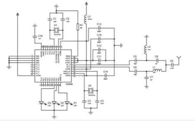
Figure 2. The connection diagram of CC2530 module.
[image:2.595.130.464.505.713.2]normally, port P0.0 will in high level; if the module receives data normally, port P0.1 will in high level; and if the module have malfunction, port P0.2 will in high level. The connection diagram of CC2530 module is shown in Figure 2. Transceivers realize multiple hops transmission among each device by using ZigBee protocol.
Embedded chip MSP430 series MCU is selected as the controller in the removable guardrail system [5]. The MSP430 MCU is a single chip microcomputer which consists of 16 bit low power Flash memory. The working voltage of the microprocessor module is 1.8V~3.6V. And these interrupts can be nested arbitrarily. When this system is in a low power consumption state, it can be waked up by interrupt within 5μs.
Stepper Motor Module
[image:3.595.218.383.329.445.2]As shown in Figure 3, the stepper motor module consists of stepper motor and motor driver chip. The motor is a two-phase hybrid stepping motor, angle of precession is 1.8 degree. The design adopts concurrent control mode, the controller can control the motor to rotate by putting an ordered pulse current to winding in order. MSP430 must output PWM wave according to timing sequence through the I/O ports to control the stepper motor [6]. Since stepper motor need work in high voltage and large power, so TTL voltage cannot drive the motor directly. Therefore motor driver chip must be used to drive the stepper motor. Motor driver chip can select ULN2003A.
Figure 3. The connection diagram of the Stepper motor module.
The Removable Guardrail Device
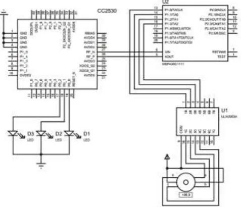
Figure 4. The connection diagram of the removable guardrail device.
[image:3.595.172.411.508.713.2]5V and 3.3V voltage-stabilizer circuit within the removable guardrail device, the 5V voltage-stabilizer circuit supplies power to the microcomputer, and the 3.3V to CC2530 module [8].
System Software Design
PC User Software Design
[image:4.595.173.423.219.386.2]The PC software of the system is composed of MFC interface. Software interface is shown in Figure 5. User can directly through the software control removable guardrail device state. It has the characteristics of high instructions transmission speed and high execution accuracy.
Figure 5. User software using interface.
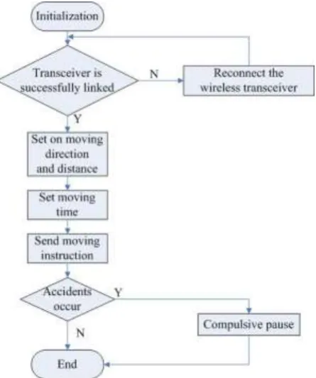
The flow chart of software is shown in Figure 6. When opening the software, software starts initialization. Then the software will automatically detect whether wireless transceiver is successfully linked. If not, it will show the words "invalid ports"; if successful, no words appear. Then the user can set on the moving direction and distance of guardrail at the interface, and then set the moving time. The user clicks "start moving" button and the guardrail start to move. When finishing instruction execution, guardrail has moved to the specified location.
[image:4.595.188.411.500.767.2]If the time of the "tidal phenomenon" is relatively fixed, the user can choose timing options. When there are accidents, such as accident occurs, user can select “compulsive pause” button to stop moving guardrail. Finally, the user selects “exit” button to exit the software.
Controller Software Design
The program design of the MSP430 control system selects the C language, MSP430 control the rotation of the motor through PWM wave [9]. In the initialization phase of the program, the system sets the timer T1 in mode 2, baud rate, and start timer T2. Serial port work in mode 1, setting the SMOD=1, it continuously receives data from user terminal. MCU will test whether the serial port transmission is completed constantly. If not, serial port continues to receive data; otherwise, clear the sign. Next judging whether is start/stop instruction, MCU will start the motor after receiving the instruction. At the same time, the MCU outputs instruction to the serial port. When MCU detects the counter of Timer is full, the motor will stop moving, and exit the interrupt program.
In this program, the microcontroller receives moving instructions information from user terminal, including moving direction, distance and timing information. Then it receives data, CC2530 sends moving instructions to next guardrail device to drive it moving. The ULN2003 drives stepping motor moving, after guardrail devices move to specified location the wheels will automatically lockup.
Performance Analysis
In this section, we can estimate the moving distance of the removable guardrail device in each pulse cycle through the theoretical calculation. And through model test, we discover that the theoretical calculation correspond to reality. The error of moving distance is small.
A. The moving distance of the stepper motor
1. Step angle: Every time the stator winding of stepper motor changes power-up State. The angle of the rotor turns is called step angle:
2
m Z C
(1)
where, m is the stator phase number, Z is the rotor teeth number, and C is electricity way (when one-phase take turns to electricity C=1, when one-phase and bi-phase take turns to electricity C=2).
2. Revolving speed of the stepper motor: The revolving speed of the stepper motor is according to Pulse frequency inputted to the stepper motor and step angle:
2
f
n
(2)
3. Linear speed:
2
V R n (3) where, R is radius of wheel.
4. Moving distance:
S V t (4) where, t is moving time. In combination with Eq.(2) and Eq.(3), we can find the relationship between step angle and moving distance:
S Rft (5)
When t=T (T is the Pulse cycle inputted to the stepper motor), we can find the moving distance of the stepper motor in each pulse cycle:
That is to say, the moving distance of the stepper motor in each pulse cycle is only related to step angle and radius of wheel.
B. The moving distance of the system model
Because in the system motor is a mixed two-phase hybrid stepper motor, m=2, Z=50, C=2,
R=4.8cm, therefore, the results is 1.8 and S1.508 10 3m.
C. Error calculation
The accuracy of stepper motor is accounted for 5% of the step angle, and stepper motor have no cumulative error. If 1.8, the error is 0.09°. According to Eq.(6), S7.540 10 5m. When the system move 1 meter, the maximum error brought by the accuracy of stepper motor is about 5cm. The moving distance of the system is precise.
D. Model test and analysis
We set the time of moving 1 meter as 663T in the program. According to the theoretical calculation, the moving distance of the model should be S=0.9998m. The average moving distance of multi-measurement result is S 1.032m. So the system has the characteristics of small moving error and high precision.The main reason of error is the influence of accuracy error of stepper motor and the cycle value of moving. Through stepper motor subdividing and optimizer can reduce the moving error.
Conclusion
This paper designs a Removable Guardrail System Based on ZigBee wireless sensor network . Compared to traditional tidal lines, the biggest innovation of this system is using ZigBee wireless sensor network. The guardrails devices using wireless sensor network to ensure all guardrails to move at the same time.The system is applied to two-way lanes whose tidal phenomenon is severe. By remote controlling removable guardrails to change the width of the road on both sides, this system improves the traffic jam greatly, brings more convenient trips and avoids the disadvantages of existing tidal line such as lack of flexibility. The system is safe and reliable, without staff moving guardrails. At the same time, the system has great flexibility. It can change guardrails’ moving state in the case of an emergency so that improves the efficiency of event processing. Through calculating and experimental test, the maximum distance error of the system is less than 5 cm. The error is caused by precision of stepper motor.
Acknowledgement
This work was supported by the National Natural Science Foundation of China under Grant No. 61403068 and No. 61501100; Fundamental Research Funds for the Central Universities of China under Grant No. N130323002 and No. N130323004; Natural Science Foundation of Hebei Province under Grant No. F2015501097 and No. F2016501080; Scientific Research Fund of Hebei Provincial Education Department under Grant No. Z2014078; NEUQ internal funding under Grant No. XNB201509 and XNB201510.
References
[1] J. Chen, Y. Huo. Study on setting design of variable lane on typical tide traffic road. Journal of Chongqing Jiaotong University, 27 (2008): 1127-1130.
[2] G. Zhang. Study on the setting of reversible lane in urban road engineering, Transportation Science & Technology. 3 (2012): 116-119.
[4] J. Xia. Design and Implementation of ZigBee-Based WSN Experiment Platform, International Conference on Smart Grid and Electrical Automation, 2016: 280-283.
[5] X. Yuan, J. Li. Hardware Design of Fall Detection System Based on ADXL345 Sensor, 8th International Conference on Intelligent Computation Technology and Automation, 2015: 446-449.
[6] Y. Jia, J. Liu, F. Jiang. Design of DC motor wireless controller based on MCU MSP430, International Conference on Mechatronic Sciences, Electric Engineering and Computer, 2013: 3492-3495.
[7] I.G. Rania, A.S. Ihab, A.S. Karam. Real-Time Radiological Monitoring of Nuclear Facilities Using ZigBee Technology, IEEE Sensors Journal, 14 (2014): 4007-4013.
[8] H.T. Chinyang. Coordinator Traffic Diffusion for Data-Intensive Zigbee Transmission in Real-time Electrocardiography Monitoring, IEEE Transactions on Biomedical Engineering, 60 (2013): 3340-3346.