Iris Recognition based Image Authentication
K. Seetharaman
Associate Professor
Department of Computer Science and Engineering Annamalai University, Annamalai Nagar, Chidambaram,Tamil Nadu-608002, India
R. Ragupathy
Assistant Professor
Department of Computer Science and Engineering Annamalai University, Annamalai Nagar, Chidambaram,Tamil Nadu-608002, India
ABSTRACT
This paper introduces an efficient approach to protect the ownership by hiding iris code from iris recognition system into digital image for an authentication purpose using the reversible watermarking scheme. This scheme embeds bookkeeping data of histogram modification and iris code into the first level high frequency sub-bands of images found by Integer Wavelet Transform (IWT) using threshold embedding technique. The watermarked-image carrying iris code is obtained after applying inverse IWT. Simply by reversing the embedding process, the original image and iris code are extracted back from watermarked-image. Authentication is done using the metric called Hamming Distance.Experimental results show that this approach outperforms the prior arts in terms of PSNR. Also, we tested with different attacks on watermarked-image for showing the sustainability of the system.
General Terms
Pattern Recognition, Image Authentication, Wavelet, Iris.
Keywords
Iris code, Reversible watermarking, Hamming distance, Integer wavelet transforms, Iris recognition.
1.
INTRODUCTION
Biometric watermark is a technique that creates a link between a human subject and the digital media by embedding biometric information into the digital object. Watermarking biometric data is growing importance and is under research for authentication systems. According to Low et al. [1], biometric watermarking was introduced as the synergistic integration of biometrics and digital watermarking technology. In the battle of copyright piracy, several technological approaches and solutions have been suggested and implemented in [2]. The watermark is nowadays used in conjunction with several biometrics including fingerprint [3], signature [4], face [5], hand [6], voice[7], retina[8].
Choice of biometric technology should also include consideration of the following parameters, taking into consideration of the operational requirements. The parameters are Accuracy, Environment e.g. fully deployed battlefield, Ergonomics/ User-friendly, Stability and uniqueness of feature to be measured, Secure, Safety, Speeds of enrolment and recognition, Non-intrusiveness, Convenience, Cost, Size of stored template, Operational limitations e.g. finger and facial recognition through Nuclear Biological, Chemical/Chemical Biological Radiation clothing, Requirement ability to perform both identification and verification, Credible scientific background research, Human Acceptance and Robust. After consideration of all of the afore-mentioned biometric technologies, Iris is taken for our research work.
However, as the need for security increases, research for more permanent form of biometric, which is difficult to replicate, is considered. One such biometric is human iris. Iris recognition is based on visible features, i.e. rings, furrows, freckles, and corona and is considered very challenging, as they possess a high degree of randomness. The Iris is completely formed by 8th month of adults, and remains stable through life. Statistically more accurate than even DNA matching since the probability of 2 irises being identical is 1 in 10 to the power of 78 [9].Iris is unique and best biometrics that is mainly used for the establishment of instant personal identity [10]. Compared with other biometric technologies, such as face, speech and finger recognition, iris recognition can easily be considered as the most reliable form of biometric technology [11]. However, they are susceptible to accidental and intentional attacks, when transmitted over network. Thus, a protective scheme is needed which will preserve fidelity and prevent alterations. This is more important with respect to biometric identifiers because of their uniqueness. A good solution to this situation is watermarking [12]. Several techniques exist for the protection of biometric data but this paper discusses a technique that integrates iris and digital watermarking for authentication reasons. Combining digital watermark and biometric for authentication is an emerging area.
In most authentication techniques based on watermarking, the original image is inevitably distorted due to the authentication itself. Typically, this distortion cannot be removed completely due to quantization, bit-replacement, or truncation at the grayscale 0 and 255. Although the distortion is often quite small, it may be unacceptable for medical or legal imagery or images with a high strategic importance in certain military applications. Thus, it is desired to undo the changes introduced by authentication if the image is verified as authentic. Data embedding techniques satisfying this requirement, are referred to as reversible (also referred as lossless) image authentication techniques.To achieve the reversibility, invertible integer-to-integer wavelet transforms [13] areused. Yang et al. proposed a reversible watermarking scheme based on an integer discrete cosine transform (DCT) transform [14]. Xuan et al. reversibly embedded the watermark bits into the middle- and high-frequency integer wavelet coefficients [15]. Coltuc et al. proposed a reversible watermarking scheme based on an integer transform for pairs of pixels [16] and generalized it for groups of an arbitrary number of pixels. Tian [17] embeds the data using the difference expansion technique, resulting in one of the bestreversible data hiding methods among all reported in the literature.
for digital images using integer wavelet transform and threshold embedding technique based on iris recognition is proposed. The proposed authentication technique is rather simple and, yet, outperforms the prior arts. Both theoretical analysis and experimental results demonstrate the superiority of the proposed technique. The rest of the paper is organized as follows. A brief introduction of histogram modification is provided in Section 2. How our Iris recognition system works is discussed in Section 3. The proposed image authentication system is presented in Section 4. Section 5 describes how hamming distance is used for authentication. Some experimental results and performance analysis are given in Section 6. The conclusion is drawn in Section 7.
2.
HISTOGRAM MODIFICATION
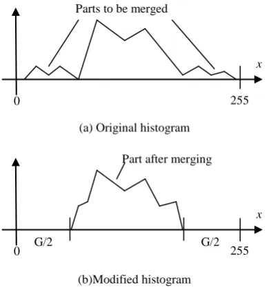
After iris codeis embedded into first level high frequency IWT coefficients, namely, HL1, LH1, HH1, it is possible that after inverse integer wavelet transform, the grayscale values of some pixels in the marked image may exceed the upper bound (255 for an eight-bit grayscale image) and/or the lower bound (0 for an eight-bit grayscale image). This phenomenon is called overflow/underflow. In order to prevent the overflow and underflow, histogram modification is applied to narrow down the histogram from both sides as shown in Fig. 1.
(a) Original histogram
[image:2.595.325.534.132.588.2](b)Modified histogram
Fig 1: Histogram modification
In order to illustrate the histogram narrow down process, we use the following simplified example, where the size of an original image is 6x6 with 8=23 grayscales (6x6x3) is shown in Fig. 2(a) and its corresponding histogram is shown in Fig. 3(a).
2 4 7 4 7 3 3 4 5 3 4 1 3 4 7 5 6 4 0 2 2 4 5 4 0 1 3 4 7 5 0 3 4 5 3 2
2 4 6 4 6 3 3 4 5 3 4 2 3 4 6 5 5 4 1 2 2 4 5 4 1 2 3 4 6 5 1 3 4 5 3 2 (a) Original Image data (b) Modified Image Data
Fig 2: Illustrative example of histogram modification
From Fig. 3(c),we can see that the range of modified histogram now is from 1 to 6 instead of from 0 to 7, i.e., no pixel assumes grayscales 0 and 7 after the histogram
modification. During the modification (Ref. Fig. 3(b)), grayscale 1 is first merged into grayscale 2. Grayscale 0 then becomes grayscale1. In the similar way, grayscale 6 is first merged into grayscale 5. Grayscale 7 then becomes grayscale 6. The modified image data is shown in Fig. 2(b).
(a) Before modification
(b) In modification
[image:2.595.69.266.331.540.2](c) After modification
Fig 3: Histogram of histogram modification process
In narrowing down a histogram to the range [G/2, 255-G/2], we need to record the histogram modification information (bookkeeping information S) as part of the embedded data.Generally the amount of bookkeeping information is small. Through bookkeeping information the original image can be restored losslessly. For the above example, the histogram is narrowed down 1 gray scalefor both sides. G=2, G/2=1. Where S is the concatenation of the total book-keeping bit length 37 bits (00100101), compressed number of gray scale 2 (010), the first histogram from left hand side grayscale ―1‖ (001), record length 6 (0110), scan sequence (101101), the first histogram from right hand side grayscale ―6‖ (110), record length 6 (0110) , and the scan sequence (110111)i.e., [00100101 010 001 0110 101101 110 0110 110111]
0 2 4 6 8 10 12
0 1 2 3 4 5 6 7
O
cc
u
re
n
ce
Gray value
0 2 4 6 8 10 12
0 1 2 3 4 5 6 7
O
cc
u
re
n
ce
Gray value
0 2 4 6 8 10 12
0 1 2 3 4 5 6 7
O
cc
u
re
n
ce
Gray value
0 255
x Part after merging
G/2 G/2
0 255
[image:2.595.54.275.617.709.2]3.
IRIS RECOGNITION SYSTEM
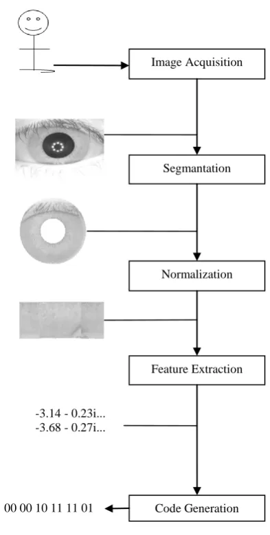
In this paper, we propose an approach for iris recognition consisting of four stages (Ref. Fig. 4): segmentation (localization), normalization, feature extractionand code generation. In this approach, Canny edge detector and Hough transforms are used to improve the speed and accuracy of the segmentation process. Segmented Iris is normalized using Daugman‘s rubber sheet model from [-320
, 320] and [1480, 2120] instead of the entire iris region. The features are
[image:3.595.322.530.136.399.2]extracted by convolving the 1D signal with help of 1D Log-Gabor filter, FFT and inverse FFT, which is called phase data. These features are encoded efficiently using phase quantization technique to produce a feature vector with discriminating texture features and a proper dimensionality so as to improve the recognition accuracy and computational efficiency.
Fig 4: Block diagram of an iris recognition system
3.1
Segmentation
The first stage of iris recognition is to isolate the actual iris region in a digital eye image. The Canny edge detector is adapted to find the edge map of the eye image and the Hough transform is employed to identify the inner and outer boundaries of the iris. The boundaries are utilized to isolated the iris region from the original eye image, which is shown in Fig. 5(d).
3.1.1
Edge detection
Edge detection is a one of the image processing technique which uses the abrupt changes in the illumination of the pixel values. Canny edge detector is a multi-step edge detection procedure and the result of Canny edge detector on eye image is given in Fig. 5(b).
(a) Original eye image (b) After applying Canny edge detector
(c) After applying Hough Transform
[image:3.595.71.268.252.642.2](d) Isolated iris region
Fig 5:Segmentation process of an iris recognition system
3.1.2
Iris and pupil boundary detection
The Hough transform is a standard computer vision algorithm that can be used to determine the parameters of simple geometric objects, such as lines and circles present in an image. The circular Hough transform is employed to deduce the radius and center coordinates of the pupil and iris regions. An edge map is generated by calculating the first derivatives of intensity values in an eye image and then thresholding the result. From the edge map, votes are cast in Hough space for the parameters of circles passing through each edge point. A maximum point in the Hough space is corresponding to the radius and center coordinates of the circle best defined by the edge points. Result of Hough transform employed on edge map of the original eye image is shown in Fig. 5(c).
3.2
Normalization
Once the iris region is successfully segmented from an eye image, the next stage is to transform the iris region so that it has fixed dimensions in order to allow comparisons. The dimensional inconsistencies between eye images are mainly due to the stretching of the iris caused by pupil dilation from varying levels of illumination. Other sources of inconsistency include, varying imaging distance, rotation of the camera, head tilt, and rotation of the eye within the eye socket. The normalization process will produce iris regions, which have the same constant dimensions, so that two photographs of the same iris under different conditions will have characteristic features at the same spatial location. Another point of note is that the pupil region is not always concentric within the iris region, and is usually slightly nasal. This must be taken into account if trying to normalize the ‗doughnut‘ shaped iris region to have constant radius. Normalization process involves unwrapping the iris and converting it into its Image Acquisition
Segmantation
Normalization
Feature Extraction
Code Generation -3.14 - 0.23i...
-3.68 - 0.27i...
polar equivalent. Result of Normalization for the segmented iris for [00, 3600] from the isolated iris region of the original eye image is shown in Fig. 6(a)
The homogenous rubber sheet model devised by Daugman [18] is used to remap each point within the iris region to a pair of polar coordinates (r,θ) wherer is on the interval [0,1] and θis angle [0,2π]. The normalized pattern is created by backtracking to find the Cartesian coordinates of data points from the radial and angular position in the normalized pattern. From the ‗doughnut‘ iris region, normalization produces a 2D array, which is shown in Fig. 6(a) with horizontal dimensions of angular resolution and vertical dimensions of radial resolution. In order to prevent non-iris region data from corrupting the normalized representation, data points which occur along the pupil border or the iris border are discarded. As we use Daugman‘s rubber sheet model, removing rotational inconsistencies is performed at the matching stage during authentication. The normalization process proved to be successful and some results are shown in [18].
Since in most cases the upper and lower parts of the iris area are occluded by eyelid, it is decided to use only the left and right parts of the iris area for iris recognition. Therefore, the whole iris [00, 3600] is not transformed in the proposed system i.e. normalizing the iris from [-320, 320] and [1480, 2120], ignoring both upper and lower eyelid areas is carried out like Mohammed A. M. Abdullah et. al. adapted in [19]. Result of Normalization from [-320, 320] and [1480, 2120] for the segmented iris from the original eye image is shown in Fig. 6(b).The size of the rectangular block is reduced accordingly. Left and right side of same iris image of size 86 × 10 is obtained. By applying this approach, detection time of upper and lower eyelids and 64.4% cost of the polar transformation are saved (Ref. Fig. 6). Results have shown that information in these portions of iris is subjective for iris recognition.
a) Normalized iris for [00, 3600] b) Normalized iris from
[-320, 320] and [1480, 2120]
Fig6:Normalization of iris
3.3
Feature extraction
Feature extraction is implemented by convolving the normalized iris pattern with 1D Log-Gabor wavelets [20]. The 2D normalized pattern is broken up into a number of 1D signal, and then these 1D signals are convolved with 1D Log-Gabor wavelets using FFT and inverse FFT [21]. The rows of the 2D normalized pattern are taken as the 1D signal; each row corresponds to a circular ring on the iris region.The angular direction is taken rather than the radial one, which corresponds to columns of the normalized pattern, since maximum independence occurs in the angular direction. The intensity values at known noise areas in the normalized pattern are set to the average intensity of surrounding pixels to prevent influence of noise in the output of the filtering. This process can be explained with the following example. Assume a 6 X 6 matrix from normalized iris, as follows
120 125 150 160 150 120 120 123 156 166 156 120 125 125 155 165 155 120 124 124 154 164 154 120 122 122 152 162 152 120 127 127 157 167 157 120
After convolution with 1D Log-Gabor wavelet filter using FFT and inverse FFT, the following complex number matrix is produced as features.
-3.14 -i0.23 -1.44 -i2.82 1.75 -i2.69 3.23 +i0.17 1.44 +i2.92 -1.84 +i2.64 -3.68 -i0.27 -1.67 -i3.31 2.06 -i3.14 3.76 +i0.21 1.68 +i3.42 -2.15 +i3.10 -3.33 -i0.23 -1.58 -i3.00 1.86 -i2.92 3.48 +i0.17 1.55 +i3.15 -1.98 +i2.82 -3.32 -i.018 -1.61 -i2.97 1.82 -i2.92 3.46 +i0.14 1.57 +i3.11 -1.93 +i2.82 -3.28 -i0.09 -1.66 -i2.89 1.73 -i2.92 3.14 +i0.07 1.61 +i3.02 -1.82 +i2.82 -3.37 -i0.32 -1.53 -i3.07 1.95 -i2.92 3.53 +i0.25 1.51 +i3.25 -2.09 +i2.82
3.4
Iris code generation
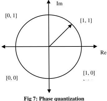
[image:4.595.341.514.280.443.2]The feature extracted using 1D Log-Gabor wavelet filter, FFT and IFFT is given as the input to the phase quantization process to produce the template with binary values of 0‘s and 1‘s. This result is also known as iris code. In the phase quantization, if both real and imaginary parts are +ve, 11 is assigned. If both real part and imaginary parts are –ve then the 00 is assigned. As well as, if the real part is +ve and imaginary part is –ve, 10 is assigned and if the real part is -ve and imaginary part is +ve , 01 is assigned. This logic is shown in Fig.7for generating the iris code.
Fig 7: Phase quantization
The output of feature extraction is phase quantized to four levels [22], with each filter producing two bits of data for each pixel. The output of phase quantization is chosen to be a grey code, so that when going from one quadrant to another, only 1 bit changes as like following.
This minimizes the number of bits disagreeing, if say two intra-class patterns are slightly misaligned and thus provide more accurate recognition. The encoding process produces a bitwise template containing a number of bits of information, even though the phase information is meaningless at regions where the amplitude is zero. The total number of bits in the template is twice the product of the angular resolution times and the radial resolution times.
4.
PROPOSED AUTHENTICATION
SYSTEM
We decided to use the CDF (Cohen-Daubechies-Fauraue) (2,2) integer wavelet transform, adopted by JPEG2000 for image lossless compression, to obtain the wavelet coefficients. Because of what is called frequency mask, the data embedded into in the first level high frequency
sub-00 sub-00 10 11 11 01 00 00 10 11 11 01 00 00 10 11 11 01 00 00 10 11 11 01 00 00 10 11 11 01 00 00 10 11 11 01
Im
Re [1, 1]
[1, 1] [1, 1] [0, 0]
[0, 1]
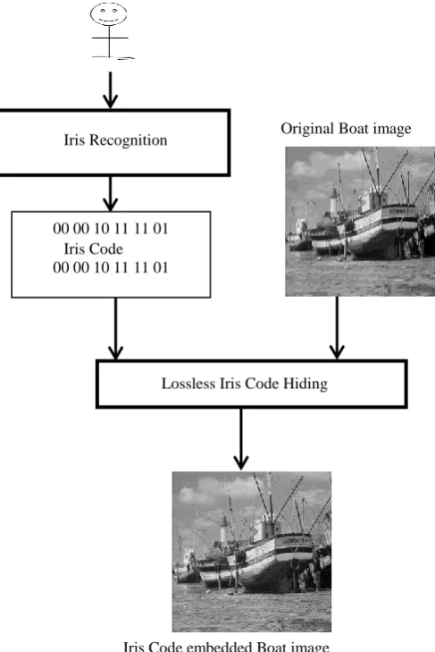
bandswill have less visible artifact to human eyes. In the enrolment process of the proposed authentication system (Ref. Fig. 8) embeds iris code, which is generated in the phase quantization process of iris recognition system, lossless into the first level high frequency sub-bands of images using threshold embedding technique.
Fig 8: Enrolment process of proposed authentication system
To embed iris code into a high frequency coefficient x, the absolute value of the coefficient is compared with predefined T. If |x| <T, the coefficient value is doubled and the new LSB is replaced with an iris code bit. The resultant coefficient is denoted by x‘. Otherwise, if x ≥ T, the coefficient will be added by T, if x ≤ -T, the coefficient will be subtracted by (T-1), and no bit is embedded into this coefficient. These rules can be summarized as eq. (1).
2*x + b, if | x | < T x’ = x + T, if x ≥ T
x – (T – 1), if x ≤ − T (1)
Histogram modification is performed prior to iris code embedding to ensure no overflow/underflow will take place. The bookkeeping data of histogram modification and the iris code are embedded into the high frequency IWT coefficients. The Watermarked-image carrying hidden iris code is obtained after inverse integer wavelet transform.
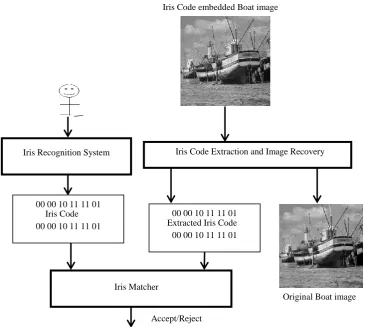
In the verification process of proposed authentication system, simply by reversing the embedding process the original image and iris code are extracted back from watermarked-image.
Then this extracted iris code is used to authenticate the original image by matching with the iris code generated from the live person as like shown in Fig. 9. This matching process is explained in the next section. At first, IWT is applied on Watermarked-image to find sub-bands with iris code, and then iris code and bookkeeping data of histogram modification are extracted from these sub-bands. For a coefficient, if it is less than 2T and larger than (-2T+1), the LSB of this coefficient is the bit embedded into this coefficient.Otherwise, we jump to the next coefficient since the current coefficient has no hidden iris code in it.
Besides hidden iris code extraction, the original cover image should able to be recovered. Concretely, each high frequency coefficient can be restored to its original value by applying the eq. (2).
𝑥′
2 , if -2T + 1 <x’ <2T
x = x’ – T, ifx’ ≥ 2T
x’ + T – 1, if x’ ≤ – 2T + 1 (2) Where y takes the largest integer value that is smaller than y. After extraction, inverse IWT is applied with untouched sub-band and processed sub-bands with iris code. Finally, original image is recovered by making inversehistogram modification.
5.
IRIS MATCHER
The Hamming distance is chosen as a metric for authentication, since bit-wise comparisons are necessary. The Hamming distance algorithm employed in such that only significant bits are used in calculating the Hamming distance between two iris codes. The Hamming distance gives a measure of how many bits are not same between two bit patterns. Using the Hamming distance of two bit patterns, a decision can be made as to whether the two patterns were generated from different irises or from the same one. In comparing the bit patterns X and Y, the Hamming distance, HD, is defined as the average of sum of disagreeing bits (Ref. eq. 3) i.e., Sum of the exclusive-OR between X and Y over Ndivided by N, the total number of bits in the bit pattern.
𝐻𝐷 = 1
𝑁 𝑋𝑗
𝑁
𝑗 =1
𝑋𝑂𝑅 𝑌𝑗
(3) Since an individual iris region contains features with high degrees of freedom, each iris region will produce a bit-pattern which is independent to that produced by another iris, on the other hand, two iris codes produced from the same iris will be highly correlated.
If two bits patterns are completely independent, such as iris templates generated from different irises, the Hammingdistance between the two patterns should equal 0.5. This occurs because independence implies the two bit patterns will be totally random, so there is 0.5 chance of setting any bit to 1, and vice versa. Therefore, half of the bits will agree and half will disagree between the two patterns. If two patterns are derived from the same iris, the Hamming distance betweenthem will be close to 0.0, since they are highly correlated. The False Match Rates, Either Observed in the Distribution of Scores or Predicted Theoretically [22] are tabulated as a Function of Possible Decision Policy Match Criteria Imposed on the Normalized Hamming Distance Scores.
In order to account for rotational inconsistencies, when the Hamming distance of two templates is calculated, one template is shifted left and right bit-wise and a number of Iris Recognition
System
Lossless Iris Code Hiding 00 00 10 11 11 01
00 00 10 11 11 01 00 00 10 11 11 01 00 00 10 11 11 01 00 00 10 11 11 01 00 00 10 11 11 01
Iris Code
Original Boat image
Hamming distance values are calculated from successive shifts. This bit-wise shifting in the horizontal direction
Fig 9: Verification process of proposed authentication system
corresponds to rotation of the original iris region by an angle given by the angular resolution used. If an angular resolution of 180 is used, each shift will correspond to a rotation of 2 degrees in the iris region. This method is suggested by Daugman [22], and corrects for misalignments in the normalized iris pattern caused by rotational differences during imaging. From the calculated Hamming distance values, only the lowest is taken, since this corresponds to the best match between two templates.
The actual number of shifts required to normalize rotational inconsistencies will be determined by the maximum angle difference between two images of the same eye, and one shift is defined as one shift to the left, followed by one shift to the right.Since, phase quantization generates two bits of information from one pixel of the normalized region, here two bits are shifted.We suggest the threshold (TH) for HD as 0.32 for CASIA-IrisV3-Interval. So if the HD value is less than TH is nearly matching, if the HD value is 0.0 is exactly matching and if the HD value is more than TH is not matching. Based on this threshold value of HD, Iris Matcher accepts/rejects the image authentication.
6.
RESULTS AND DISCUSSION
For our test, iris images are taken from CASIA-IrisV3-Interval database, freely available for research on the internet on CASIA website. We tested the proposed scheme with Lena image, Boat, Baboon, Pepper, House image etc., and various eye images in the database. The quality of watermarking is generally measured with PSNR. If it is more than 30dB, it is
good and cannot be identified by naked eye. For most of the test using threshold embedding technique, it is more than 45dB. One such example test result is shown in Fig. 10. In which, PSNR of watermarked image with original Lena image is 52.42dB for T=6, which is 2dB more than different expansion method [17]and 4dB more than DCT method [14]. For all testing without attack, original image is recovered properly and iris matcher accepts for the correct person eye and rejects for other person eye. When tested with correct person HD is closed to 0.0 but for wrong person it is more than 0.32.
a) Original Image b) Watermarked image (PSNR:
52.42dB)
c) Recovered Image
Fig 10: Result of loss less iris code hiding and extraction
Also, this paper evaluates the system based on the verification accuracy and quality of de-watermarked images. The proposed system apprised using 10 attacks, namely, Gamma (0.5) in darker, Gamma (1.5) in lighter, JPEG with Quality Factor 50%, Median Filter (3 x 3), Blurring (3 x 3), Gaussian Noise (3 x 3), Cropping (10 pixels), Resize (90%), Rotation Iris Matcher
Iris Code Extraction and Image Recovery
00 00 10 11 11 01 00 00 10 11 11 01 00 00 10 11 11 01 00 00 10 11 11 01 00 00 10 11 11 01 00 00 10 11 11 01
Extracted Iris Code
Original Boat image Iris Code embedded Boat image
Accept/Reject Iris Recognition System
00 00 10 11 11 01 00 00 10 11 11 01 00 00 10 11 11 01 00 00 10 11 11 01 00 00 10 11 11 01 00 00 10 11 11 01
[image:6.595.315.538.577.679.2](10o) and Affine Transform andalso evaluated when no attack is performed.
Table 1. Quality and verification accuracyforLena image for DCT method [14]
Attack PSNR
(dB) HD
Iris Matcher
No attack Infinity 0.000 Accepts Gamma (0.5)
Darker 33.55 0.257 Accepts Gamma (1.5)
Lighter 29.22 0.355 Rejects JPEG (50%) 30.54 0.272 Accepts Median Filter (3 x
3) 30.04 0.292 Accepts Blurring (3 x 3) 27.56 0.431 Rejects Gaussian Noise
(3x3) 35.78 0.231 Accepts Cropping (10
[image:7.595.60.271.360.566.2]pixels) NA 0.200 Accepts Resize (90%) NA 0.313 Accepts Rotation (10o) NA 0.492 Rejects Affine Transform NA 0.518 Rejects NA- Not applicable due to different size
Table 2. Quality and verification accuracyof Lena image for different expansion method [17]
Attack PSNR
(dB) HD
Iris Matcher
No attack Infinity 0.000 Accepts Gamma (0.5)
Darker 35.95 0.233 Accepts Gamma (1.5)
Lighter 31.13 0.242 Accepts JPEG (50%) 33.18 0.216 Accepts Median Filter (3 x
3) 31.37 0.248 Accepts Blurring (3 x 3) 29.11 0.331 Rejects Gaussian Noise
(3x3) 37.96 0.211 Accepts Cropping (10
[image:7.595.64.270.595.769.2]pixels) NA 0.100 Accepts Resize (90%) NA 0.299 Accepts Rotation (10o) NA 0.452 Rejects Affine Transform NA 0.495 Rejects NA- Not applicable due to different size
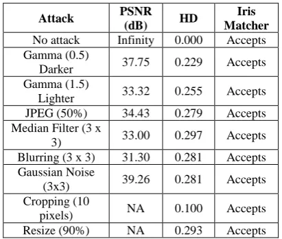
Table 3. Quality and verification accuracy of Lena image for threshold embedding method
Attack PSNR
(dB) HD
Iris Matcher
No attack Infinity 0.000 Accepts Gamma (0.5)
Darker 37.75 0.229 Accepts Gamma (1.5)
Lighter 33.32 0.255 Accepts JPEG (50%) 34.43 0.279 Accepts Median Filter (3 x
3) 33.00 0.297 Accepts Blurring (3 x 3) 31.30 0.281 Accepts Gaussian Noise
(3x3) 39.26 0.281 Accepts Cropping (10
pixels) NA 0.100 Accepts Resize (90%) NA 0.293 Accepts
Rotation (10o) NA 0.472 Rejects Affine Transform NA 0.478 Rejects NA- Not applicable due to different size
Experiments on various images for above mentioned attacks are conducted. PSNR for the original and recovered image after attack on watermarked image, HD between original iris code and extracted iris code and Iris matcher decisionof Lena image for the above mentioned attacks for DCT method [14],different expansion method [17] and threshold embedding method are given in table 1, 2 and 3 respectively.From the tabulated data it is very clear that threshold embedding method outperforms in terms of PSNR and iris matcher decision.
7.
CONCLUSION
This paper has introduced an efficient authentication watermarking scheme to protect the ownership of digital image using biometric watermarking approach. A novel lossless iris code hiding method for digital images using integer wavelet transform and threshold embedding technique is used.In Iris recognition, the iris has segmented by a simple and fast technique and introduced the 320 normalisation method to eliminate the detection time of upper and lower eyelids and to reduce 64.4% cost of the polar transformation. The original cover image can be recovered without any loss, if the watermarked-image has not been lossy processed. The visual quality of the watermarked-image and the verification accuracy even after attacks are the best among the existing lossless data hiding methods. It can be stated that the iris code can act as an access granting mechanism in the sourceand destination place and upon successful identification.As a conclusion remarks,this iris codebased reversible watermarking is an effective and efficient methodto authenticate an image.
8.
ACKNOWLEDGMENTS
Portions of the research in this paper used the CASIA iris image database collected by Institute of Automation, Chinese.
9.
REFERENCES
[1] C.Y. Low, A.B. Teoh and C. Tee, ―Fusion of LSB and DWT Biometric Watermarking Using Offline Handwritten Signature for Copyright Protection‖, Proceedings of the Third International Conference on Advances in Biometrics, Lecture Notes In Computer Science, vol. 5558, pp. 786 – 795, 2009.
[2] H.G. Schaathun, ―On watermarking/ fingerprinting for copyright protection‖, Proceedings of the First International Conference on Innovative Computing, Information and Control, IEEE Computer Society, vol. 3, pp. 50-53, 2006.
[3] S. Jain, ―Digital watermarking techniques: a case study in fingerprints & faces‖, Proceedings ICVGIP 2000, pp. 139-144, 2000.
[4] E. Maiorana, P. Campisi, A. Neri, ―Biometric Signature Authentication Using Radon Transform-Based Watermarking Techniques‖, IEEE Biometrics Symposium, pp. 1-6, 2007.
[6] A. K. Jain, K. Nandakumar and A. Nagar, ―Biometric Template Security‖, EURASIP Journal on Advances in Signal Processing, Article ID 579416, 2008.
[7] Y. Lee, H.J. Kang and Y.H. Ki, ―Copyright Authentication Enhancement of Digital Watermarking Based on Intelligent Human Visual System Scheme‖, Knowledge-Based Intelligent Information and Engineering Systems, Intelligent Watermarking Algorithms and Applications, vol. 3682, pp. 567-572, 2005.
[8] G. Coatrieux, M. Lamard, W. Daccache, W. Puentes, C. Roux, ―A Low Distortion and Reversible Watermark: Application to Angiographic Images of the Retina‖, 27th Annual International Conference of the Engineering in Medicine and Biology Society, IEEE-EMBS, pp. 2224-2227, 2005.
[9] J. Daugman and C. Downing , ―Epigenetic randomness, complexity, and singularity of human iris patterns‖, Proceedings of the Royal Society, Biological Sciences, pp. 1737 – 1740, 2001.
[10]Ajay Kumar, Arun Passi, ―Comparison and combination of iris matchers for reliable personal authentication‖, Pattern Recognition, vol. 43, pp. 1016–1026, 2010. [11]S. Sanderson, J. Erbetta, ―Authentication for secure
environments based on iris scanning technology‖, IEE Colloquium on Visual Biometrics, 2000.
[12]Nick Bartlow, Nathan Kalka, Bojan Cukic, and Arun Ross, ―Protecting Iris Images through Asymmetric Digital Watermarking‖, Proceedings of the Fifth IEEE workshop on Automatic Identification advanced Technologies, Italy, pp. 191-197, June 2007.
[13]I. Daubechies and W. Sweldens, ―Factoring wavelet transforms intolifting steps‖,Journal of Fourier Anal. Appl., vol. 4, no. 3, pp. 245–267, 1998.
[14]B. Yang, M. Schmucker, W. Funk, C. Busch, and S. Sun, ―IntegerDCT-based reversible watermarking for images using companding technique‖, Proc. SPIE, Security, Steganography, and Watermarkingof Multimedia Contents, San Jose, CA, pp. 405–415, Jan. 2004. [15]G. Xuan, Y. Q. Shi, Q. Yao, Z. Ni, C. Yang, J. Gao, and
P. Chai,―Lossless data hiding using histogram shifting method based on integerwavelets‖, LNCS, Int. Workshop Digital Watermarking,Korea, Nov. 2006. [16]D. Coltuc and A. Tremeau, ―Simple
reversiblewatermarking schemes‖, Proc. SPIE, Security, Steganography, and Watermarking of Multimedia Contents, San Jose, CA, pp. 561–568, Jan. 2005. [17]J. Tian, ―Reversible data embedding using a difference
expansion‖, IEEE Transactions on Circuits and Systems for Video Technology, pp. 890-896, August 2003. [18]J. Daugman, ―How iris recognition works‖, IEEE
transactions on circuits and systems for video technology, vol. 14, pp. 21-30, January 2004.
[19]Mohammed A. M. Abdullah, F. H. A. Al-Dulaimi, Waleed Al-Nuaimy, Ali Al-Ataby, ―Smart card with iris recognition for high security access environment‖, IEEE, pp. 382-385, 2010.
[20]D. Field, ―Relations between the statistics of natural images and the response properties of cortical cells‖, Journal of the Optical Society of America, 1987. [21]P. Duhamel, and M. Vetterli, ―Fast Fourier Transforms:
A Tutorial Review and a State of the Art‖, Signal Processing, vol. 19, pp. 259-299, April 1990.