Performance Analysis of MIMO-OFDM by Spatial
Diversity with STBC4
Bhanu
1
Department of Electronics and Telecommunication,
Lovely Professional University, Punjab
Lavish Kansal
Assistant Professor Department of Electronics andTelecommunication
Lovely Professional University, Punjab
ABSTRACT
The main aim of OFDM-MIMO systems is to combine OFDM technology with the techniques of MIMO systems. The growing demand of multimedia services and the growth of Internet related contents lead to increasing interest to high speed communications. OFDM is a type of multichannel modulation that divides a given channel into many parallel sub channels or subcarriers, so that multiple symbols are sent in parallel. In this paper, a simulation model of OFDM-MIMO system based on STBC4 is built. BER performance of the system with different number of transceiver antennas like 4X1, 4X2, 4X3, 4X4 with OFDM are analyzed and simulated under different channels considering different modulation modes such as PSK and QAM. The spatial diversity is increased by employing OFDM-MIMO with STBC.
Keywords
OFDM, MIMO, STBC, Spatial diversity, BER.
1.
INTRODUCTION
Wireless communication is one of the most vibrant areas in the communication field today. While it has been a topic of study since the 1960s, the past decade has seen a surge of research activities in the area. OFDM is one of the promising modulation candidates for a fourth generation broadband mobile communication system because of its robustness against inter-symbol interference (IS1) [1]. Orthogonal frequency division multiplexing (OFDM) technique transfers the frequency selective multi path fading channel to flat channel, so it can reduce the influence of fading [2]. Multiple antenna elements are placed both in transmitter and receiver of MIMO system [2]. Its core idea is space-time signal processing, which Use multiple antennas to increase the spatial dimension based on the equal time dimension. So it can achieve a multi-dimensional signal processing, and it obtain spatial multiplexing gain and spatial diversity gain. Multiple input multiple output (MIMO) system could increase capacity linearly with the number of transmitting receiving antennas without additional power or bandwidth [3].
The paper is organized as follows: At the beginning, the paper introduces the basic principles of MIMO and OFDM, and then further it gives space time block coding scheme of MIMO-OFDM to achieve the spatial diversity, and
analysis its performance under different channels having more number of antennas.
2.
OFDM TECHNOLOGY
In this section, the physical layer of OFDM is implemented.
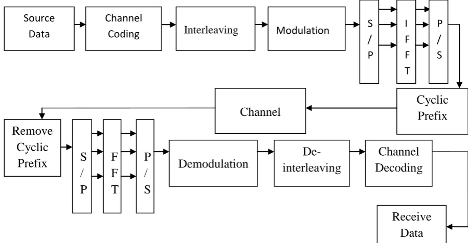
Figure 1 shows the block diagram of an OFDM system with SISO configuration. Different blocks are implemented.
2.1 Source Coding
Source coding entails the efficient representation of information sources. For both discrete and continuous sources, the correlations between samples are exploited to produce an efficient representation of the information. The aim of source coding is either to improve the SNR for a given bit rate or to reduce the bit rate for a given SNR. An obvious benefit of the latter is a reduction in the necessary system resource of bandwidth and/or energy per bit to transmit the information source. A discussion on source coding requires the definition of a quantity, which measures the average self information in each discrete alphabet, termed source entropy [4].
2.2 Channel Encoding and Decoding
Figure 1 OFDM Block Diagram
2.3
Interleaving and Deinterleaving
Interleaving aims to distribute transmitted bits in time or frequency or both to achieve desirable bit error distribution after demodulation. All encoded data bits shall be interleaved by a block interleaver with a block size corresponding to the number of bits in a single OFDM symbol. The interleaver is defined by a two-step permutation. The first permutation ensures that adjacent coded bits are mapped onto nonadjacent subcarriers. The second ensures that adjacent coded bits are mapped alternately onto less and more significant bits of the constellation and, thereby, long runs of low reliability (LSB) bits are avoided.[6] Deinterleaving is the opposite operation of interleaving; i.e., the bits are put back into the original order.
2.4
.
Modulation and Demodulation
In telecommunications, modulation is the process of conveying a message signal. Digital modulation is the mapping of data bits to signal waveforms that can be transmitted over an analog channel. The data that we want to transmit over the wireless propogation channel are-digital – either because we really want to transmit data files or because the source coder has rendered the source information into digital format. On the other hand, the wireless propogation channel is an analog medium, over which analog waveforms have to be sent [7]. For this reason, modulator is used at the transmitter side to convert the digital source data to analog waveforms and at the receiver side; demodulator is used to recover the bits from the received waveform.
2.5. IFFT and FFT
IFFT is useful for OFDM because it generates samples of a waveform with frequency component satisfying orthogonality condition. It also removes the need of oscillator However, by calculating the outputs simultaneously and taking advantage
of the cyclic properties of the multipliers Fast Fourier Transform (FFT) techniques reduce the number of computations to the order of N log N. The FFT is most efficient when N is a power of two. Several variations of the FFT exist, with different ordering of the inputs and outputs, and different use of temporary memory. FFT can be implemented in two ways i.e. DIT and DIF. for DIT, the input is bit-reversed and output is in natural order, while in DIF, the reverse is true [8]. FFT can be implemented in two ways i.e. DIT and DIF. Two main differences between decimation in time and decimation in frequency. First, for DIT, the input is bit-reversed and output is in natural order, while in DIF, the reverse is true. Secondly, for DIT complex multiplication is performed before the add-subtract operation, while in DIF the order is reversed. Secondly, for DIT complex multiplication is performed before the add-subtract operation, while in DIF the order is reversed. While complexity of the two structures is similar in typical DFT, this is not the case for partial FFT
2.6
Cyclic Prefix Insertion and Removal
One way to prevent IS1 is to create a cyclically extended guard interval, where each OFDM symbol is preceded by a periodic extension of the signal itself. At the receiver, removing the guard interval becomes equivalent to removing the cyclic prefix.
N L
Figure 2. Cyclic Prefix in OFDM Transmission
Cyclic
Prefix
Channel
Remove
Cyclic
Prefix
S
/
P
F
F
T
P
/
S
Demodulation
De-interleaving
Channel
Decoding
Receive
Data
Source
Data
Channel
Coding
Interleaving
Modulation
S
/
P
I
F
F
T
P
/
S
[image:2.595.321.549.657.713.2]When the guard interval is longer than the channel impulse response, or the multipath delay, the IS1 can be eliminated [9]. However, the ICI, or in-band fading, still exists. The ratio of the guard interval to useful symbol duration is application dependent. Since the insertion of guard interval will reduce data throughput L is usually less than N/4.
2.7
Channel
Channel, refers either to a physical transmission medium such as a wire, or to a logical connection over a multiplexed medium such as a radio channel. A channel is used to convey an information signal, for example a digital bit stream, from one or several senders (or transmitters) to one or several receivers. A channel has a certain capacity for transmitting information, often measured by its bandwidth in Hz or its data rate in bits per second. It is not so smooth as received signal is not coming directly from the transmitter, but the combination of reflection, diffraction and scattered copies of the transmitted signals. Reflection occurs when the signal hits a surface where partial energy is reflected and the remaining is transmitted into the surface. Radio signals may also undergo diffraction. It is found that when signals encounter an obstacle they tend to travel around them. This can mean that a signal may be received from a transmitter even though it may be "shaded" by a large object between them. This is particularly noticeable on some long wave broadcast transmissions. Scattering occurs when the signal impinges upon rough surfaces, or small objects [10]. Types of Channels:-
2.7.1.
AWGN Channel
2.7.2.
Fading Channels
2.7.2.1 Rayleigh Fading Chanel
2.7.2.2 Rician Fading Channel
2.7.2.3 Nakagami Fading Channel
3.
MIMO TECHNOLOGY
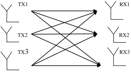
MIMO technology has been developed over many years. In radio, multiple-input and multiple-output, or MIMO, is the use of multiple antennas at both the transmitter and receiver to improve communication performance. It is one of several forms of smart antenna technology. The terms input and output refer to the radio channel carrying the signal, not to the devices having antennas.
TX1 RX1
TX2 RX2
TX
3
RX3 [image:3.595.67.283.573.697.2]
Figure 3. Diagram of MIMO system with M Transmitters and N Receivers
MIMO has attracted a great attention
in wireless communications, because it offers significant increases in data throughput and link range without additional
bandwidth. MIMO is performing better in terms of channel capacity in a rich scatter multipath environment than in case of environment with LOS. This fact was spectacularly shown in [11].
In MIMO systems, a transmitter sends multiple streams by multiple transmit antennas as shown in figure above. The transmit streams go through a matrix channel which consists of all MTMR paths between the MT transmit antennas at the
transmitter and MR receive antennas at the receiver. Then, the
receiver gets the received signal vectors by the multiple receive antennas and decodes the received signal vectors into the original information.
Because of these properties, MIMO is an important part of modern wireless communication standards such as IEEE 802.11n (Wi-Fi), 4G, 3GPP Long Term Evolution, WiMAX and HSPA+. MIMO systems may be implemented in a number of different ways to obtain either a diversity gain to combat signal fading or to obtain a capacity gain. Spatial Diversity is one of the methodology.
3.1
Spatial Diversity
Diversity is one of the ways to combat this multipath fading. The main idea behind diversity is to provide different replicas of the transmitted signal to the receiver. If these different replicas fade independently, it is less probable to have all copies of the transmitted signal in deep fade simultaneously [12]. MIMO take advantage of the spatial diversity obtained by placing separate antennas in a dense multipath scattering environment. These systems can be implemented in a number of different ways to obtain either a diversity gain to combat signal fading or a capacity improvement. Therefore, the receiver can reliably decode the transmitted signal using these received signals. This technique involves Space Time Block Coding (STBC) and Space Time Trellis Coding (STTC). Diversity techniques can be implemented into different ways.
3.2
Spatial Multiplexing
The first MIMO spatial multiplexing system is proposed in [13], known as D-BLAST (Diagonal Bell Labs Layered Space-Time). To reduce complexity, a V-BLAST system is introduced [14]. The key for spatial multiplexing is how to recover the original transmitted data stream. The received signals from different antennas interfere with each other. Theoretically, to get rid of the mutual interference, the number of receiver antennas has to be equal to or larger than the number of transmitter antennas. The receiver signal processing algorithm can be based on zero forcing, minimum mean squared error (MMSE), or maximum likelihood (ML). Multi-user detection algorithms initially designed for CDMA systems [15] can also be used for spatial multiplexing MIMO receive processing.
3.3
Beam Forming
A nonlinear interpolation and a modified clustering based transmit beam forming schemes are investigated by J. Huang et.al to reduce the feedback information and improve performance for a MIMO-OFDM system [16]. It exploits the knowledge of channel at the transmitter. It decomposes the channel coefficient matrix using SVD and uses these decomposed unitary matrices as pre- and post-filters at the transmitter and the receiver to achieve near capacity.
3.4.
Interference Reduction and Avoidance
0 20 40 60 80 100 120 10-4
10-3 10-2 10-1 10
0
signal to noise ratio(dB)
b
it
e
rr
o
r
ra
te
Bit error rate for 32psk modulation for different channels 1/2
STBC4 4X1
STBC4 4X2
STBC4 4X3
STBC4 4X4
OFDM
0 20 40 60 80 100 120
10
-4
10-3 10
-2
10
-1
100
signal to noise ratio(dB)
b
it
e
rr
o
r
ra
te
Bit error rate for 64psk modulation for different channels 1/2
STBC4 4X1
STBC4 4X2
STBC4 4X3
STBC4 4X4
OFDM
dimension to increase the separation between users. For instance, in the presence of interference, array gainincreases the tolerance to noise as well as the interference power, hence improving the signal-to-noise-plus-interference ratio (SINR). Additionally, the spatial dimension may be leveraged forthe purposes of interference avoidance, i.e., directing signal energy towards the intended userand minimizing interference to other users. Interference reduction and avoidance improve thecoverage and range of a wireless network.
4.
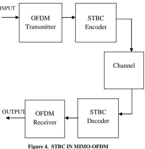
STBC IN OFDM-MIMO
OFDM PHY. Layer as well as MIMO systems have been implemented till now. Further work on OFDM-MIMO has been done for low modulations and low antenna configurations. In MIMO systems, Alamouti scheme has been implemented till now. The transmit diversity technique proposed by Alamouti was the first STBC .Firstly we implement block diagram of OFDM. After that we will combine OFDM with MIMO systems with the help of STBC encoder and decoder at the transmitter and receiver side.
INPUT
[image:4.595.72.316.292.543.2]
OUTPUT
Figure 4. STBC IN MIMO-OFDM
The data is encoded by a channel code and the encoded data is split into multiple streams that are simultaneously transmitted using multiple transmit antennas [17]. The received signal at each receive antenna is a linear superposition of the different transmitted signals. The performance criteria for designing channel codes under the assumption that the fading is slow and frequency non-selective is also derived. Performance is shown to be determined by diversity gain quantified by ranks and coding gain quantified by determinants of certain matrices that are constructed from the code sequences. A detailed analytical behavior and BER performance of the system with different number of transceiver antennas is given [17], [18].
5.
RESULTS & DISCUSSIONS
In this report behaviour of the MIMO-OFDM under different modulation environments is studied and the effects of increasing the order of the modulation on the BER performance of the system are presented. The system
discussed above has been designed using the STBC4 code structure for MIMO-OFDM system. Results are shown in the form of SNR vs BER plot for different modulations and different channels. The performance of MIMO-OFDM system is analyzed using BER analysis
.
5.1 BER Analysis of MIMO-OFDM System
In this section BER analysis of MIMO-OFDM system using STBC4 code structure is done for higher order Modulations over Nakagami and Rician channel. First, M-PSK is presented over Nakagami fading channel.
5.1.1 M-PSK over Nakagami Fading Channel
Over code rate 1/2
(a) 32-PSK
(b) 64-PSK
OFDM
Transmitter
STBC
Encoder
Channel
STBC
Decoder
OFDM
0 20 40 60 80 100 120 10-4
10-3 10-2 10-1 100
signal to noise ratio(dB)
bi
t
er
ro
r
ra
te
Bit error rate for 128psk modulation for different channels 1/2
STBC4 4X1
STBC4 4X2
STBC4 4X3
STBC4 4X4
OFDM
0 20 40 60 80 100 120
10-4 10-3 10-2 10-1 10
0
signal to noise ratio(dB)
bi
t
er
ro
r
ra
te
Bit error rate for 256psk modulation for different channels 1/2
STBC4 4X1
STBC4 4X2
STBC4 4X3
STBC4 4X4
OFDM
0 20 40 60 80 100 120
10 -4 10
-3 10
-2 10
-1 10
0
signal to noise ratio(dB)
bi
t
er
ro
r
ra
te
Bit error rate for 512psk modulation for different channels 1/2
STBC4 4X1 STBC4 4X2 STBC4 4X3 STBC4 4X4 OFDM
0 20 40 60 80 100 120
10-4 10-3 10-2 10-1 100
signal to noise ratio(dB)
bi
t
er
ro
r
ra
te
Bit error rate for 1024psk modulation for different channels 1/2
STBC4 4X1
STBC4 4X2
STBC4 4X3
STBC4 4X4
OFDM
(c) 128-PSK
(d) 256-PSK
(e) 512-PSK
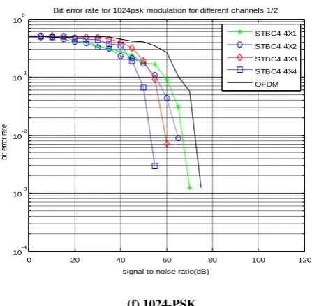
[image:5.595.328.552.82.301.2](f) 1024-PSK
Figure 5.4: (a)-(f) SNR vs. BER plots for M-PSK over Nakagami channel with code rate 1/2
a) 32-PSK b) 64-PSK c) 128-PSK d) 256-PSK e) 512 -PSK (f) 1024-PSK
[image:5.595.316.548.479.721.2]For MIMO-OFDM system SNR vs. BER plots for M-PSK over Nakagami channel with different code rates 1/2 have been presented in fig5.4 (a) – (f) employing different antenna configurations. These graphs depicts as we increasing the number of transmitting and receiver antennas , the BER keeps on decreasing due to spatial diversity and provide better BER performance as compared to OFDM.
Table 5.4: SNR improvement for M-PSK in Nakagami channel with 1/2
Different Modulation Levels SNR improvement
for
AWGN Channel (db)
32-PSK 5 dB
64-PSK 5 dB
128-PSK 5 dB
256-PSK 5 dB
512-PSK 5 dB
0 20 40 60 80 100 120 10-4
10-3 10
-2 10
-1 10
0
signal to noise ratio(dB)
bi
t e
rro
r r
at
e
Bit error rate for 32psk modulation for different channels 2/3
STBC4 4X1 STBC4 4X2 STBC4 4X3 STBC4 4X4 OFDM
0 20 40 60 80 100 120
10 -4 10
-3 10-2 10
-1 100
signal to noise ratio(dB)
bi
t e
rro
r r
at
e
Bit error rate for 128psk modulation for different channels 2/3
STBC4 4X1 STBC4 4X2 STBC4 4X3 STBC4 4X4 OFDM
0 20 40 60 80 100 120
10-4 10-3 10-2 10-1 10
0
signal to noise ratio(dB)
bi
t e
rro
r r
at
e
Bit error rate for 64psk modulation for different channels 2/3
STBC4 4X1 STBC4 4X2 STBC4 4X3 STBC4 4X4 OFDM
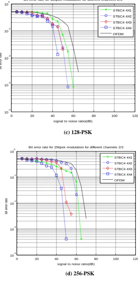
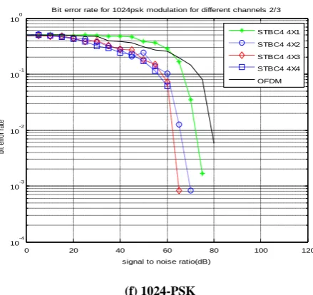
5.1.2
M-PSK over Nakagami Fading Channel
with Code Rate 2/3.
(a) 32-PSK
(b) 64-PSK
(c) 128-PSK
(d) 256-PSK
(e) 512-PSK
[image:6.595.325.557.76.497.2](f) 1024-PSK
Figure 5.5: (a)-(e) SNR vs. BER plots for M- PSK over Nakagami channel with code rate 2/3
a) 32-PSK b) 64-PSK c) 128-PSK d) 256-PSK e) 512-PSK (f) 1024-PSK
0 20 40 60 80 100 120
10 -4 10-3 10-2 10-1 100
signal to noise ratio(dB)
bi
t e
rro
r r
at
e
Bit error rate for 256psk modulation for different channels 2/3
STBC4 4X1 STBC4 4X2 STBC4 4X3 STBC4 4X4 OFDM
0 20 40 60 80 100 120
10-4 10-3 10-2 10
-1 10
0
signal to noise ratio(dB)
bi
t e
rro
r r
at
e
Bit error rate for 512psk modulation for different channels 2/3
STBC4 4X1 STBC4 4X2 STBC4 4X3 STBC4 4X4 OFDM
0 20 40 60 80 100 120
10 -4 10
-3 10
-2 10
-1 100
signal to noise ratio(dB)
bi
t e
rro
r r
at
e
Bit error rate for 1024psk modulation for different channels 2/3
0 20 40 60 80 100 120 10-4
10 -3 10
-2 10
-1 10
0
signal to noise ratio(dB)
bi
t e
rro
r r
at
e
Bit error rate for 128psk modulation for different channels 3/4
STBC4 4X1 STBC4 4X2 STBC4 4X3 STBC4 4X4 OFDM
0 20 40 60 80 100 120
10-4 10-3 10
-2 10
-1 10
0
signal to noise ratio(dB)
bi
t e
rro
r r
at
e
Bit error rate for 256psk modulation for different channels 3/4
STBC4 4X1 STBC4 4X2 STBC4 4X3 STBC4 4X4 OFDM
[image:7.595.83.305.201.436.2]SNR vs. BER plots for M-PSK over Nakagami channel for MIMO-OFDM system with different code rates 2/3 have been presented in fig 5.5 (a) – (f) employing different antenna configurations. These graphs depicts as we increasing the number of transmitting and receiver antennas , the BER keeps on decreasing and provide better BER performance as compared to OFDM due to spatial diversity.
Table 5.5: SNR improvement for M-PSK in Nakagami channel with 2/3
Different Modulation Levels SNR improvement
for
AWGN Channel (db)
32-PSK 5 dB
64-PSK 5 dB
128-PSK 5 dB
256-PSK 5 dB
512-PSK 5 dB
1024-PSK 5dB
5.1.3 M-PSK over Nakagami Fading Channel
with Code Rate 3/4.
(a) 32-PSK
(b) 64-PSK
(c) 128-PSK
(d) 256-PSK
0 20 40 60 80 100 120
10 -4 10
-3 10
-2 10
-1 100
signal to noise ratio(dB)
bi
t e
rro
r r
at
e
Bit error rate for 32psk modulation for different channels 3/4
STBC4 4X1 STBC4 4X2 STBC4 4X3 STBC4 4X4 OFDM
0 20 40 60 80 100 120
10-4 10-3 10-2 10-1 10
0
signal to noise ratio(dB)
bi
t e
rro
r r
at
e
Bit error rate for 64psk modulation for different channels 1/2
0 20 40 60 80 100 120 10-4
10-3 10-2 10-1 100
signal to noise ratio(dB)
bi
t e
rro
r r
at
e
Bit error rate for 32psk modulation for different channels 1/2
STBC4 4X1
STBC4 4X2
STBC4 4X3
STBC4 4X4
OFDM
0 20 40 60 80 100 120
10-4 10-3 10-2 10-1 100
signal to noise ratio(dB)
bi
t
er
ro
r
ra
te
Bit error rate for 512psk modulation for different channels 3/4
STBC4 4X1
STBC4 4X2
STBC4 4X3
STBC4 4X4
OFDM
0 20 40 60 80 100 120
10-4 10-3 10-2 10-1 100
signal to noise ratio(dB)
bi
t
er
ro
r
ra
te
Bit error rate for 1024psk modulation for different channels 3/4
STBC4 4X1
STBC4 4X2
STBC4 4X3
STBC4 4X4
OFDM
(e) 512-PSK
(f) 1024-PSK
Figure 5.6: (a)-(f) SNR vs. BER plots for M-PSK over Nakagami channel with code rate 3/4 a) 32-PSK b) 64-PSK c) 128-PSK d) 256-PSK
For M-PSK over Nakagami channel for MIMO-OFDM system employing different antenna configurations with different code rates 3/4 SNR vs. BER plots have been presented in fig5.6 (a) – (f). Graphs shows as we increasing the number of transmitting and receiver antennas, the BER keeps on decreasing due to spatial diversity and provide better BER performance as compared to OFDM.
Table5.6: SNR improvement for M-PSK in Nakagami channel with 3/4
Different Modulation Levels SNR
improvement for
AWGN Channel (db)
32-PSK 5 dB
64-PSK 5 dB
128-PSK 5 dB
256-PSK 5 dB
512-PSK 5 dB
1024-PSK 5 dB
5.2 Rician Channel
5.2.1 M-PSK over Rician Fading Channel with
Code Rate 1/2
0 20 40 60 80 100 120 10
-4 10
-3 10
-2 10
-1 100
signal to noise ratio(dB)
bi
t
er
ro
r
ra
te
Bit error rate for 128psk modulation for different channels 1/2
STBC4 4X1 STBC4 4X2 STBC4 4X3 STBC4 4X4 OFDM
0 20 40 60 80 100 120
10 -4 10-3 10
-2 10
-1 100
signal to noise ratio(dB)
bi
t e
rro
r r
at
e
Bit error rate for 64psk modulation for different channels 1/2
STBC4 4X1 STBC4 4X2 STBC4 4X3 STBC4 4X4 OFDM
0 20 40 60 80 100 120
10 -4 10
-3 10
-2 10
-1 10
0
signal to noise ratio(dB)
bi
t
er
ro
r
ra
te
Bit error rate for 256psk modulation for different channels 1/2
STBC4 4X1 STBC4 4X2 STBC4 4X3 STBC4 4X4 OFDM
0 20 40 60 80 100 120
10-4 10
-3 10-2 10
-1 10
0
signal to noise ratio(dB)
bi
t e
rro
r r
at
e
Bit error rate for 512psk modulation for different channels 1/2
STBC4 4X1 STBC4 4X2 STBC4 4X3 STBC4 4X4 OFDM
0 20 40 60 80 100 120
10-4 10-3 10-2 10-1 100
signal to noise ratio(dB)
bi
t
er
ro
r
ra
te
Bit error rate for 1024psk modulation for different channels 1/2
STBC4 4X1
STBC4 4X2
STBC4 4X3
STBC4 4X4
OFDM
(b) 64-PSK
(c) 128-PSK
(d) 256-PSK
(e) 512-PSK
[image:9.595.333.562.77.509.2](f) 1024-PSK
Figure 5.7: (a)-(f) SNR vs. BER plots for M-PSK over Rician channel with code rate1/2
a) 32-PSK b) 64-PSK c) 128-PSK d) 256-PSK e) 512-PSK (f) 1024-PSK
0 20 40 60 80 100 120 10
-4 10-3 10-2 10-1 100
signal to noise ratio(dB)
bi
t e
rro
r r
at
e
Bit error rate for 32psk modulation for different channels 2/3
STBC4 4X1 STBC4 4X2 STBC4 4X3 STBC4 4X4 OFDM
0 20 40 60 80 100 120
10-4 10
-3 10-2 10-1 100
signal to noise ratio(dB)
bi
t e
rro
r r
at
e
Bit error rate for 64psk modulation for different channels 2/3
STBC4 4X1 STBC4 4X2 STBC4 4X3 STBC4 4X4 OFDM
0 20 40 60 80 100 120
10
-4
10-3 10-2 10-1 100
signal to noise ratio(dB)
bi
t
er
ro
r
ra
te
Bit error rate for 128psk modulation for different channels 2/3
STBC4 4X1
STBC4 4X2
STBC4 4X3
STBC4 4X4
OFDM
0 20 40 60 80 100 120
10-4 10-3 10-2 10-1 100
signal to noise ratio(dB)
bi
t
er
ro
r
ra
te
Bit error rate for 256psk modulation for different channels 2/3
STBC4 4X1
STBC4 4X2
STBC4 4X3
STBC4 4X4
OFDM
0 20 40 60 80 100 120
10-4 10
-3
10-2 10-1 100
signal to noise ratio(dB)
bi
t
er
ro
r
ra
te
Bit error rate for 512psk modulation for different channels 2/3
STBC4 4X1
STBC4 4X2
STBC4 4X3
STBC4 4X4
[image:10.595.339.565.80.541.2]OFDM
Table 5.7: SNR improvement for M-PSK in Rician channel with 1/2
Different Modulation Levels SNR improvement forAWGNChannel (db)
32-PSK 5 dB
64-PSK 5 dB
128-PSK 5 dB
256-PSK 5 dB
512-PSK 5 dB
1024-PSK 5dB
5.2.2 M-PSK Over Rician Fading Channel
With Code Rate 2/3
(a) 32-PSK
(b) 64-PSK
(c) 128-PSK
(d) 256-PSK
0 20 40 60 80 100 120 10
-4 10
-3 10-2 10-1 10
0
signal to noise ratio(dB)
bi
t e
rro
r r
at
e
Bit error rate for 32psk modulation for different channels 3/4
STBC4 4X1 STBC4 4X2 STBC4 4X3 STBC4 4X4 OFDM
0 20 40 60 80 100 120
10 -4 10-3 10-2 10
-1 10
0
signal to noise ratio(dB)
bi
t e
rro
r r
at
e
Bit error rate for 64psk modulation for different channels 3/4
STBC4 4X1 STBC4 4X2 STBC4 4X3 STBC4 4X4 OFDM
0 20 40 60 80 100 120
10-4 10-3 10-2 10-1 100
signal to noise ratio(dB)
bi
t e
rro
r r
at
e
Bit error rate for 128psk modulation for different channels 3/4
STBC4 4X1 STBC4 4X2 STBC4 4X3 STBC4 4X4 OFDM
0 20 40 60 80 100 120
10 -4 10-3 10
-2 10
-1 10
0
signal to noise ratio(dB)
bi
t e
rr
or
r
at
e
Bit error rate for 1024psk modulation for different channels 2/3
STBC4 4X1 STBC4 4X2 STBC4 4X3 STBC4 4X4 OFDM
[image:11.595.90.310.70.277.2](f) 1024-PSK
Figure 5.8: (a)-(f) SNR vs. BER plots for M-PSK over Rician channel with code rate 2/3
a) 32-PSK b) 64-PSK c) 128-PSK d) 256-PSK e) 512-PSK (f) 1024-PSK
M-PSK over Rician channel for MIMO-OFDM system employing different antenna configurations with different code rates 2/3 SNR vs BER plots have been presented in fig5.8 (a) – (f). These graphs depicts as we increasing the number of transmitting and receiver antennas , the BER keeps on decreasing due to spatial diversity and provide better BER performance as compared to OFDM.
Table 5.8: SNR improvement for M-PSK in Rician channel with 2/3
Different Modulation Levels SNR
improvement for AWGN Channel (db)
32-PSK 5 dB
64-PSK 5 dB
128-PSK 5 dB
256-PSK 5 dB
512-PSK 5 dB
1024-PSK 5dB
5.2.3 M-PSK Over Rician Fading Channel
With Code Rate 3/4.
(a) 32-PSK
(b) 64-PSK
[image:11.595.331.566.91.760.2]
0 20 40 60 80 100 120 10-4
10 -3 10
-2 10-1 100
signal to noise ratio(dB)
bi
t e
rro
r r
at
e
Bit error rate for 256psk modulation for different channels 3/4
STBC4 4X1 STBC4 4X2 STBC4 4X3 STBC4 4X4 OFDM
0 20 40 60 80 100 120
10-4 10-3 10-2 10-1 10
0
signal to noise ratio(dB)
bi
t e
rro
r r
at
e
Bit error rate for 512psk modulation for different channels 3/4
STBC4 4X1 STBC4 4X2 STBC4 4X3 STBC4 4X4 OFDM
(d) 256-PSK
(e) 512-PSK (f) 1024-PSK
Figure 5.9: (a)-(f) SNR vs. BER plots for M-PSK over Rician channel with code rate 3/4
a) 32-PSK b) 64-PSK c) 128-PSK d) 256-PSK e) 512-PSK
(f) 1024-PSK
[image:12.595.75.306.69.506.2]For MIMO-OFDM system with different code rates 3/4 SNR vs. BER plots for M-PSK over Rician channel have been presented in fig 5.9 (a) – (f). Graphs shows as we increasing the number of transmitting and receiver antennas, the BER keeps on decreasing due to spatial diversity and provide better BER performance as compared to OFDM.
Table5.9: SNR improvement for M-PSK in Rician channel with 3/4
Different Modulation Levels SNR improvement for AWGN Channel (db)
32-PSK 5 dB
64-PSK 5 dB
128-PSK 5 dB
256-PSK 5 dB
512-PSK 5 dB
1024-PSK 5 dB
6. CONCLUSION
In the present work, an idea about the performance of the MIMO-OFDM systems at higher modulation levels and for different antenna configurations is presented. Performance of MIMO OFDM system is analyzed under different fading channels. MIMO-OFDM system can be implemented using higher order modulations to achieve large data capacity. The motive of using high order antenna configuration (4 X 4) is to increase the space diversity, which will further decrease the BER at given SNR as compared to lower order Antenna configurations namely 1 X 1, 2 X 2, 4 X 4 and 6 X 6. By doing so, even higher data capacity at any given SNR can be achieved. The system is tested under Nakagami and Rician channel environments. The BER will decrease on increasing the no. of Transmitters or Receivers due to spatial diversity. The motive of using high order antenna configuration (4 X 4) is to increase the space diversity, which will further decrease the BER at given SNR as compared to lower order Antenna configurations namely 1 X 1, 2 X 2, 4 X 4 and 6 X 6. By doing so, even higher data capacity at any given SNR can be achieved.
0 20 40 60 80 100 120
10-4 10
-3 10-2 10-1 100
signal to noise ratio(dB)
bi
t e
rro
r r
at
e
Bit error rate for 1024psk modulation for different channels 3/4
7.
ACKNOWLEDGEMENTS
It gives me great pleasure to have opportunity to acknowledge and to express gratitude to those who were associated with my thesis. First of all I would like to thank to my guide Mr. Lavish Kansal had given me his full support in guiding me. I would also like to thank Ms. Geetanjali for her kind support during this work. I am also thankful to Mr. Bhupinder Verma, Head of
Department, for providing us with the adequate infrastructure in carrying the work. At last I shall always remain
indebted to them for their excellent guidance in my thesis.
8. REFERENCES
[1] Chang-Jun Ahn & lwao Sasase, “The effects of modulation combination, target ber, doppler frequency, and adaptation interval on the performance of adaptive
ofdm in broadband mobile channel” IEEE
Transactions on Consumer Electronics , Vol.48, Issue 1, pp-167-174, 2002.
[2] Z. Jie, L. liang & LI jin , “Performance Analysis of Space Time Block Code in MIMO-OFDM Systems” International Conference on Communication Software and Networks, pp-13-16, 2011.
[3] S. H. & Deuk-Su Lyu, “Physical Layer Implementation and Evaluation of Multiple Input Multiple Output- Orthogonal Frequency Division Multiplexing (MIMO-OFDM) System” International
Conference on Communication Technology
Proceedings, Vol.2, pp-1348-1352, 2003.
[4] B. P. Lathi, “Modern Digital and Analog Communication Systems”by CBS College Publishing, 1983.
[5] IEEE Standard 802.11a White Paper. IEEE Standards Board.
[6] IEEE Standard 802.11a. IEEE Standards Board 1999 Edition. Piscatawa, USA.
[7] P. S. Mundra, T. L. Singal & R. Kapur, “The Choice of A Digital Modulation, Schemes in A Mobile Radio System”, IEEE Vehicular Technology Conference, Issue 5, pp 14, 1993.
[8] A. Sadat & W. B. Mikhael, “Fast Fourier Transform for
High Speed OFDM Wireless Multimedia System”, 44th
IEEE Midwest symposium on circuits and systems, Vol. 2, pp 938-942, 2001.
[9] W. Henkel, G. Taubock, P. Odling, P. O. Borjesson & N. Petersson, “The Cyclic Prefix of OFDM/DMT– A Analysis”, International Zurich Seminar on Broadband Communications, Issue 2, pp 1-3, 2002.
[10] E. Casas & C. Leung, “Performance of OFDM/FM scheme for data transmission over fading mobile radio channels”, 36th IEEE Vehicular Technology Conference, Vol. 36, Issue 5, pp 103-108, 1986.
[11] A. V. Zelst & T. C. W. Schenk, “Implementation of a MIMO OFDM-Based Wireless LAN System,” IEEE Transaction on Signal Processing, Vol. 52, Issue 2, pp 483-494, February 2004.
[12] H. Hourani, “An overview of diversity techniques in wireless communication systems,” IEEE JSAC, pp. 1200-5, October 2004.
[13] G. J. Foschini, “Layered space-time architecture for wireless communication in a fading environment when using multi-element antennas”, Bell Labs Tech. J., vol. 1, no. 2, pp. 41 - 59, 1996.
[14] G. J. Foschini, G. D. Golden, P. W. Wolniansky, & R. A. Valenzuela, “Simplified processing for wireless communication at high spectral efficiency”, IEEE J. Select. Areas Commun. vol. 17, pp. 1841 – 1852, Nov. 1999.
[15] S. Verdu, Multiuser Detection. Cambridge University Press, 1998.
[16] J. Huang, J. Zhang, Z. Liu, J. Li & X. Li, “Transmit Beam forming for MIMO-OFDM Systems with Limited Feedback”, IEEE Vehicular Technology Conference, pp 1-5, 2008.
[17] V. Tarokh, N. Seshadri & A. R. Calderbank, “Space–
Time Codes for High Data Rate Wireless
Communication: Performance Criterion and Code Construction”, IEEE Transactions on Information Theory, Vol. 44, Issue 2, pp 744-765, 1998.