FPGA based High Speed Double Precision Floating
Point Divider
Addanki Purna Ramesh
Department of ECE,Sri Vasavi Engineering College, Pedatadepalli, Tadepalligudem, India.
Dhanalakshmi Balusu
Department of ECE,Sri Vasavi Engineering College, Pedatadepalli, Tadepalligudem, India.
ABSTRACT
Floating point arithmetic is widely used in many areas, especially scientific computation and signal processing. For many signal processing, and graphics applications, it is acceptable to trade off some accuracy (in the least significant bit positions) for faster and better implementations. Division is the third basic operation of arithmetic. However, most of these modern applications need higher frequency or low latency of operations with minimal area occupancy. In this paper we describe an implementation of high speed IEEE 754 double precision floating point divider using digit recurrence algorithm and targeted for Xilinx Virtex-6 Field Programmable Gate Array. Verilog is used to implement the design. The implemented design achieves 344.89 MFlops and this design occupies 653 slices. It handles the overflow, underflow and rounding mode.
Keywords
Double precision, Floating point, Divider, FPGA, IEEE-754, and Virtex6
1. INTRODUCTION
Floating point numbers are one possible way of representing real numbers in binary format. The IEEE 754 standard presents two different floating point formats, Binary interchange format and Decimal interchange format. Multiplying floating point numbers is a critical requirement for DSP applications involving large dynamic range. This paper focuses on double precision floating point binary interchange format. Figure.1 shows the IEEE 754 double precision floating point binary format representation. It consists of a one bit sign (S), an eleven bits exponent (E), and a fifty two bits fraction (M or Mantissa). An extra bit is added to the fraction to form what is called the significand1. If the exponent is greater than 0 and smaller than 2047, and there is 1 in the MSB of the significand then the number is said to be a normalized number, Significand is the mantissa with an extra MSB bit.
Z = (-1S) * 2 (E - Bias) * (1.M)
Where M = m51 2-1 + m50 2-2 + m49 2-3+…+ m1 2-51+ m0 2 -52
Bias = 1023.
Figure 1: IEEE Double precision floating point format
2. IMPLEMENTATION OF HIGH
SPEED
DOUBLE
PRECISION
FLOATING POINT DIVIDER
.The double precision floating point divider performs operation such as division. The Black box view of double precision floating point divider is shown in figure2.
The input signals to the top level module are 1. Clk
2. Rst 3. Enable
4. Rmode (Rounding mode)
Rounding Modes selected for various bit combinations of rmode
Bit
combination
Rounding Mode
00 round_nearest_even 01 round_to_zero 10 round_up 11 round_down
The output signals from the module are 1. Out (output from operation, 64 bits) 2. Ready
3. Underflow 4. Overflow 5. Inexact 6. Exception 7. Invalid
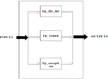
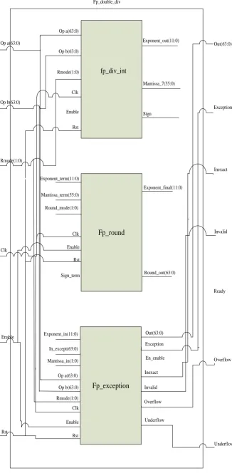
The block diagram and inter-connections of the three sub-modules of the double precision floating point divider is shown in figure 3 and 4 respectively. The sub modules of double precision floating point divider are listed below.
[image:2.595.183.436.176.439.2]1. Fp_div_int 2. Fp_round 3.Fp_exception .
[image:2.595.129.490.479.741.2]Figure 2: Black box view of High Speed double precision floating point divider
fp_div_int
Mantissa_7(55:0)
Sign
Exponent_out(11:0) Op a(63:0)
Op b(63:0)
Rmode(1:0)
Clk
Enable
Rst
Fp_round
Fp_exception
Exponent_term(11:0)
Mantissa_term(55:0)
Round_mode(1:0)
Enable
Rst
Sign_term
Exponent_final(11:0)
Round_out(63:0)
Exponent_in(11:0)
Clk
In_except(63:0)
Mantissa_in(1:0)
Op a(63:0)
Op b(63:0)
Rmode(1:0)
Clk
Enable
Rst
Out(63:0)
Exception
En_enable
Inexact
Invalid
Overflow
Underflow Op a(63:0)
Op b(63:0)
Rmode(1:0)
Clk
Enable
Rst
Out(63:0)
Exception
Inexact
Invalid
Ready
Overflow
[image:3.595.152.479.79.745.2]Underflow Fp_double_div
The divide operation is performed in the module (fp_div_int). The leading ‘1’ (if normalized) and mantissa of operand A is the dividend, and the leading ‘1’ (if normalized) and mantissa of operand B is the divisor. The divide is executed long hand style, with one bit of the quotient calculated each clock cycle based on a comparison between the dividend register (dividend_reg) and the divisor register (divisor_reg). If the dividend is greater than the divisor, the quotient bit is ‘1’, and then the divisor is subtracted from the dividend, this difference is shifted one bit to the left, and it becomes the dividend for the next clock cycle. If the dividend is less than the divisor, the dividend is shifted one bit to the left, and then this shifted value becomes the dividend for the next clock cycle.
The exponent for the divide operation is calculated from the exponent fields of operands A and B. The exponent of operand A is added to 1023, and then the exponent of operand B is subtracted from this sum. The result is the exponent value of the output of the divide operation. If the result is less than 0, the quotient will be right shifted by the amount. The divide operation takes 54 clock cycles to complete, as it takes 1 clock cycle to calculate each of the 54 bits of the quotient. The register (count_out) counts down from 53 to 0, and when it reaches 0, the 54-bit quotient register has its final value. The value that is passed on to the rounding module is stored in the 56-bit register (mantissa_7). The first most significant bit is a ‘0’ to hold a value in case of overflow in the rounding stage, the next bit is the leading ‘1’ for normalized numbers, and the next 52 bits are the mantissa bits. The remaining 2 bits are extra bits for rounding purposes. The first extra bit is the last bit that was calculated in the quotient. The quotient
has 54 bits, while the mantissa and leading ‘1’ are only 53 bits, so the extra bit is saved and passed on to the rounding stage. The second extra bit is calculated by performing an OR on all of the remainder bits that were leftover after the last compare between the dividend and divisor registers.
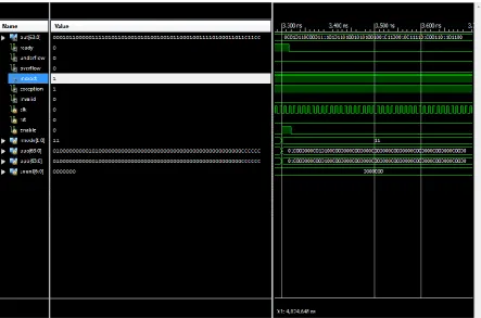
3. SIMULATION RESULTS
The simulation results of double precision floating point divider are shown in figure 5. Here the inputs opa, opb and the outputs for addition and subtraction as shown in below.
Input A: 5.0000000000e+000 Input B: 2.5000000000e+000 Enable = 1'b1;
Opa =
64'b01000000000101000000000000000000000000000000 00000000000000000000;
Opb =
64'b01000000000001000000000000000000000000000000 00000000000000000000;
Output:
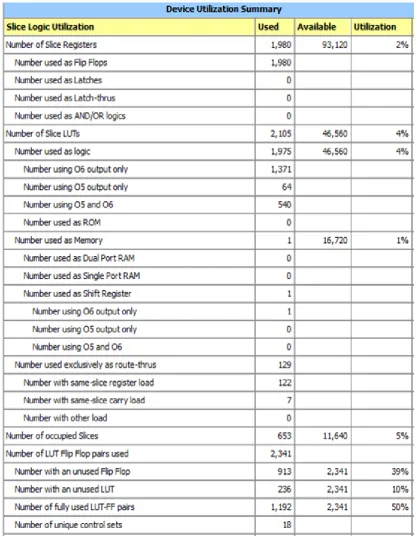
[image:4.595.88.532.453.746.2]The Device utilization summery of high speed double precision floating point divider is shown in figure 6. Table 1 and 2 shows the Timing Summary and Area and Frequency Comparison between the High Speed Double Precision Floating Point divider and reference paper [1] .The high speed double precision floating point divider targeting on Virtex-6 xc6vlx75t-3ff484 with a Frequency of 344.89 MHz, it required area is 653 slices.
Figure 6 : Device utilization summery of High Speed double precision floating point divider
Table 1 : Timing summary for High Speed double precision floating point divider Sl. No Parameter
1 Minimum period (ns) 2.899
2 Max Frequency (MHz) 344.89
3 Minimum input arrival time before clock (ns) 1.520
Table 2: Area and Frequency Comparison between the High Speed Double Precision Floating Point divider and reference paper in [1]
Device parameters Our Floating Point divider (Virtex-6)
In [1]
No of slices 653
265 MHz No of Flip flops 1980
Max Frequency (MHz) 344.89
4 CONCLUSIONS
The high speed double precision floating point divider supports the IEEE 754 binary interchange format, targeted on a Xilinx Virtex-6 xc6vlx75t-3ff484 FPGA. It achieved 344.89 MFLOPs which is 30% fast compared to reference paper [1]. This design occupies 653 slices which is less area compared to reference paper [1]. In view of used flip flops this design uses 1980 flip flops. This design handles the overflow, underflow and rounding mode.
5 REFERENCES
[1] Shamna.K, and S.R Ramesh,” Design and Implementation of an Optimized Double Precision Floating Point Divider on FPGA” International Journal of Advanced Science and Technology Vol. 18, pp.41-48, May, 2010.
[2] K. Scott Hemmert and Keith D. Underwood “Floating Point Divider Design for FPGAs”, IEEE Transaction on very large scale integration systems,vol. 15, No. 1, pp. 115-118,Jan 2007.
[3] Anuja Jayraj Thakkar and Abdel Ejnioui “Design and Implementation of Double Precision Floating Point Divider and Square Root Operations on FPGAs,”IEEE Conference on field programmable technology, 2006. [4] X .Wang and B.E Nelson, "Tradeoffs of designing
floating point division and square root on virtex fpgas”, International Conference on engineering of reconfigurable systems and algorithms, 2004.
[5] S. Paschalakis and P. Lee,”Double precision Floating point arithmetic on fpgas "IEEE Conference on field programmable technology, 2003.
[6] S.F. Oberman and M.J. Flynn, “Division Algorithms and Implementations,” IEEE Trans. Computers, vol. 46, no. 8, pp. 833-854, Aug. 1997
[7] Peter Soderquist, Miriam Leeser, "Division and Square Root: Choosing the Right Implementation,"IEEE Micro, vol. 17, no. 4, pp. 56-66, July/Aug. 1997