Reliable and Load Balanced Multi-path Routing for
Multiple Sinks in Wireless Sensor Networks
U.B. Mahadevaswamy
Associate Professor, Department of Electronics and Communication, Sri Jayachamarajendra College of
Engineering, Mysore, Karnataka, India.
M.N. Shanmukhaswamy
Professor, Department of Electronics and Communication, Sri Jayachamarajendra College ofEngineering, Mysore, Karnataka, India.
ABSTRACT
In Wireless Sensor Networks, the existing techniques for sink deployment consider load balancing and multipath routing. But the fault detection and recovery of sinks are rarely considered. In this paper, we propose to develop a Fault detection and recovery mechanism for multiple sinks. The nodes are grouped into clusters based on the data generation rate and multiple sinks are deployed in the clusters in which the data generation rate is more. An energy efficient multi path tree is constructed towards the sink and the aggregated data from the sensors are transmitted to their nearest sinks through this multi path tree. The rate adjustment value and the inter arrival delay of each path is calculated and sent back as a feedback to the source to by the respective sinks. Then the path with the minimum feedback value is chosen as the best path for transmission. When a failure occurs in a sink, then it can be detected based on delay and remaining energy. Once the fault sink is detected, then the data is transferred to another sink or the sinks are deployed again. From our simulation results, we show that an efficient load balanced multi path routing for multiple sinks is obtained and the fault detection and recovery can be made effectively.
Key words
Wireless Sensor Networks (WSN), Data Gathering, multiple sinks, Multi-path Routing,
1. INTRODUCTION
1.1 Wireless Sensor Networks
Several homogeneous or heterogeneous sensors are required in wireless sensor network (WSN) in order to organize the data collaboration or network data collection sink routing. [1]. Sensor nodes are more advantageous due to their simple installation, self-identification, self-diagnosis, reliability, time awareness for coordination with other nodes, some software functions and DSP, and standard control protocols and network interfaces. Lynx Technologies, and various Bluetooth kits, including the Casira devices from Cambridge Silicon Radio, and CSR are the commercially available wireless communication nodes [2]. The actuators that extend control from cyberspace into the physical world are controlled by the WSN. Monitoring remote environments for low frequency data trends is the most basic application of the WSN. Motes are the small system platforms, which integrate sensors, processors, and transceivers. Sensing, computing, and communicating are the three classes of WSN energy consumption. [1]
1.2 Data Gathering
The general task of the sensor networks is to transport information sampled at sensor nodes to central base stations for further processing and analysis, which is done by data gathering. Data aggregation has become an important topic in addition to severe energy constraints of sensor nodes and limited transport capacity of multihop wireless networks. In order to reduce expensive data transmission, the sensor data in the network is pre-processed by the sensor nodes. [3]
The communication cost can be reduced by data aggregation protocols which prolong the lifetime of sensor networks. Though, Tree based or cluster based structured approaches were focused previously and suited for data gathering applications, they incur high maintenance overhead in dynamic scenarios for event-based applications. Since the sensor networks have a higher communication cost than the computation cost, the data aggregation technique is considered as an effective technique. In-network data aggregation can eliminate the inherent redundancy in raw data collected from the sensors. Additionally, they are also used for extracting application specific information from raw data. [4].
Few data gathering techniques were discussed previously.
The maximum lifetime data-gathering problem was solved by a polynomial time algorithm. It was assumed to be a fixed location of the sensors and the base station. The data is transferred periodically by each sensor and it has the ability to transmit packets to any other sensor or directly to the base station [5].
A randomized algorithm was proposed for routing information on a grid of sensors. This results in near-optimum performance. [6]
A loosely coupled distributed architecture is presented to support both aggregation and more complicated in-network computation through declarative queries, which is known as the query-driven approach or Cougar. [7]
1.3 Multi-Path Routing
First k shortest paths are found in the multi-path routing and the load is divided evenly among these paths. Few multi-path routing protocols are discussed here.
Disjoint Paths: The primary path is most preferred in the sensor-disjoint path routing than the alternate paths due to their longer latency. And so the alternate paths are independent of the primary path. A failure on the primary path doesn’t affect any of the alternate paths because the disjoint makes alternate path independent.
Braided paths: A primary path is constructed and for each of its node, the best path is computed from a source sensor to the sink that does not include that node. The best alternate are not essentially disjoint from primary path and they are called as idealized braided multi-paths.
N-to-1 Multi-path Discovery: A simple flooding originating from the sink is the basis for N-to-1 multi-path discovery. Branch aware flooding and multi-path extension of flooding are the two phases. [9].
Direct communication protocols facilitating direct communication between the source node and the base station were the earlier schemes. Energy resources are used excessively which results in a complete drainage of power on a certain path when the base station is far away from the node. [10]
2. PROBLEM IDENTIFICATION
In our first paper [11], we have proposed an energy efficient reliable multi-path routing algorithm for data gathering in wireless sensor networks. In the first phase, the sink periodically broadcast an interest message containing its required data model, to all the nodes. In the second phase, we construct a multi path tree, in which nodes are selected based on their residual energy level. In the third phase, data sources of similar interests are gathered and transmitted towards the sink across the energy-efficient tree. When data sources cannot be aggregated, they are dispersed along multiple paths using erasure-coding technique
In our second paper [12], we have provided solution by designing a sink based monitoring scheme. In this scheme, sink nodes are considered which helps in distributing the data rates over paths for optimizing the network resources. For detecting the path failures the sink monitors the inter-arrival delay of data packets on each path and it also determines the new data sending rate for each path. Then it sends a feedback packet to the source which consists of the failure status of each path along with data sending rate. The source then selects the failure free paths and distributes the packets according to their data-sending rate.
In our third paper [21] , we have developed a Load balanced Multi path routing using multiple sinks in order to reduce the overload of the single sink in wireless sensor networks. The nodes are grouped into clusters based on the data generation rate. The fixed sink deploys multiple sinks in various clusters based upon their DR value. The aggregated data from sensors are transmitted through the multiple paths to their corresponding nearest sink. The task of monitoring the paths is distributed to these multiple sinks. Initially in a path, the nodes send information of its node rank and the inter-arrival delay of the links to its nearest sink. Each sink calculates the inter-arrival delay for its path in the cluster and also calculates the data sending rate based on the rank. The feedback packets of each path are sent back to the source by the multiple sinks. When the source receives the feedback packet from all the
sinks it selects the path with minimum inter arrival delay and distributes the packets according to their data sending rate.
But if any one of the multiple sinks fails, it should be detected and the corresponding gathered data from that sink should be recovered. Hence, we propose a simple technique to detect the failure of the sinks and reroute the data from the sensors to another possible sink.
3. RELATED WORK
Haeyong Kim et al [13] have proposed a paper to maximize network lifetime and to ensure fairness, they propose (i) how to position multiple sink nodes in a sensor network and (ii) how to route traffic flow from all of the sensors to these multiple sink nodes. Both of the problems are formulated by the linear programming model to find optimal locations of the multiple sink nodes and the optimal traffic flow rate of routing paths in wireless sensor networks.
Haiyang Liu et al [14] have proposed a novel routing framework called PWave that supports multi-source multi-sink anycast routing for wireless sensor networks. A distributed and scalable potential field estimation algorithm and a probabilistic forwarding scheme are proposed to ensure low overhead and high resilience to network dynamics. Key properties of this framework are proved through theoretical analysis and verified through simulations.
Mujdat Soyturk et al [15] have proposed that mobile multiple sink usage enhances the energy-related performance metrics in large scale networks. They use the Stateless Weight Routing with Multiple Sinks (MS-SWR) for routing. Mobile sink nodes are used to enhance the performance metrics.
Waleed Alsalih et al [16] have proposed a mobile base station placement scheme for extending the lifetime of the network. In their scheme the life of the network is divided into rounds and base stations are moved to new locations at the beginning of each round. While previous work has focused on placing the base stations at predefined spots or at the boundary of the network they define and solve a more general problem in which a base station can be placed anywhere in the sensing field. They formulated the problem as an Integer Linear Program (ILP) and use an ILP solver (with a constant time limit) to find a near-optimal placement of the base stations and to find routing patterns to deliver collected data to base stations.
Zolt´an Vincze et al [17] have proposed a mathematical model to determine the sink locations that minimize the average communication distances. Based on the results of the model they had proposed two sink deploying algorithms. The global algorithm uses global information about the locations of the sensor nodes in the network, while during the operation of 1hop the sinks know only the location of the neighboring sensors.
Bashir Yahya and Jalel Ben-Othman [19] have proposed a robust and energy efficient multipath routing protocol (REER). It uses the residual energy, node available buffer size, and Signal-to-Noise Ratio (SNR) to predict the best next hop through the paths construction phase. In the first method of traffic allocation, a single path among the discovered paths is used to transfer the data message. When this path cost falls bellow a certain threshold, it then switches to the next alternative path. The second method of traffic allocation is to split up the transmitted message into number of segments of equal size, add XOR-based error correction codes, and then transmit it across multiple paths simultaneously to increase the probability that an essential portion of the packet is received at the destination without incurring excessive delay.
Shujiang LI et al. [20] have proposed a multipath energy-efficient routing protocol for WSN that considers wireless interference. In that routing protocol, nodes in the interference zone of the discovered path are marked and not allowed to take part in the subsequent routing process. The network load is distributed on multiple paths instead of concentrating on only one path, and node energy cost is more balanced for the entire wireless network.
4. PROPOSED SOLUTION
4.1 Deploying Multiple Sinks
The nodes are arranged into clusters depending on their data generation rate. Then sinks are placed in the clusters in which nodes have maximum data generation rate. The method uses an iterative procedure to determine the centroids of the clusters, i.e., the places where sinks’ resultant vector is zero. In every cluster, at first the sink calculates the resultant vector R. If R is non-zero then it moves in the direction determined by the resultant vector, i.e., its new location is P + R*Ms, where Ms is the length of the maximal possible step for a sink. This iteration step is repeated until at least one of the sinks moves.
Let Data generation rate of the sensors be DR, the present position of the node be P, the resultant vector be R, Th1, Th2… are the thresholds for different data generation rates. X be the threshold value for the resultant vector. Let Ni = N1, N2, ….. be the nodes.
1. Initially, each sensor node estimates its DR and exchanges with other nodes.
2. The nodes are organized into clusters depending upon the DR value. (ie) Nodes with similar DR or DR within a specified range, form a cluster.
3. Let ci{iNi/DRiThi},i1,2,....
4. Select clusters CjwithDRjThmax(ie)
5. cj{iNi/DRiThmax}
6. The sinks are deployed on these clusters.
7. After that the sinks wait for a certain time period ensuring that within this time interval every sensor sends at least one message to the sinks.
8. Determine the ID of the original sensor node, when a sink receives a message from a sensor.
9. The number of sensors sending the messages is determined at the end of the period.
10. The R for each sink is calculated.
11. If RX ,
Sink moves to position P + R*Ms Else
Sink remains at P. Stop the process.
Example
Here, we consider the topology of figure1 as an example for the deployment of the sink nodes.
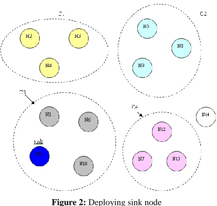
[image:3.612.340.548.227.417.2]Let N1, N2…N14 be the sensor nodes. The data generation rate (DR) is calculated for each node and the clusters are formed depending upon the DR. We form four clusters C1, C2, C3 and C4.
Figure 1: Formation of Clusters
Formation of Clusters
The DR values of the nodes along with the cluster are denoted in the table1. From the table, we can see that,
The nodes N2, N3, and N4 have DR < 25, and thus they are arranged in the cluster C1.
The nodes N5, N8, and N9 have DR < 45, so they are arranged in the cluster C2.
The nodes N1, N6, N10, and N11 have DR< 55, and they form a cluster C3.
The nodes N7, N12 and N13 have DR < 40, so they are organized in the cluster C4.
Cluster Nodes (Packets per second) Data generation rate
C1
N2 21
N3 19
N4 20
C2
N5 41
N8 39
N9 40
C3
N1 48
N6 52
N10 49
N11 50
C4
N7 35
N12 36
For sink deployment, the condition }
/
{i Ni DRi Thmax
cj needs to be satisfied. Here, we assume that the maximum data generation Thmaxas 45
Since DR of C1, C2, and C4 less than 45, they don’t satisfy the condition.
[image:4.612.65.287.189.399.2] C3 has DR> 45, so it satisfies the condition. The sink gets deployed in C3.
Figure 2: Deploying sink node
4.2 Periodic Interest Propagation by the Sinks
In the previous paper [11], the sink periodically broadcast an interest message containing its required data model, to all the nodes. On receiving the interest message the source transmits the corresponding data to the sink nodes. The data packets having similar interests are collected and aggregated at intermediate aggregators. The sink does not have any information on the availability of data while transmitting the first interest message. So the sink simply broadcasts interest message to all its neighbors. Interest message contains the Interest Id, Description and Timestamp. Due to this the sink gets overloaded and there are chances of energy depletion and faults.Initially the fixed sink in the network deploys multiple sinks in the clusters based upon their DR value as explained in the section 4.1. The fixed sink broadcasts its interest message to all other sinks. The multiple sinks in turn will broadcast the interest message to its nearest neighbors. An interest table is maintained by each node, which contains the fields sink ID, Interest Id, Sender Id, Cost of the message in terms of hop count and Timestamp. The sink ID is used to identify, from which sink the interest is transmitted.
When a node delivers the first interest message, the table checks its sink ID and the messages are added in the interest table with its parameters. The interest message is then rebroadcast to other nodes. It checks the interest table, if a duplicate interest message is received by a node. The duplicate message is dropped when the cost of it is higher than the cost of the earlier message; else it is updated in the table and then forwarded to the next node.
4.3 Data Transmission Phase
In the second paper [12], the sink monitors the inter-arrival delay of data packets on each path for detecting the path failures and it determines the new data-sending rate for each path. Then it sends a feedback packet to the source, which consists of the failure status of each path along with data sending rate. The source then selects the failure free paths and distributes the packets according to their data-sending rate.
In this paper, the aggregated data from sensors are transmitted through the multiple paths to their corresponding nearest sink so that overload of the sink can be reduced. The task of monitoring the paths is now distributed to this multiple sinks. Initially in a path, the nodes send information of its node rank and the inter-arrival delay of the links to its nearest sink. Each sink calculates the inter-arrival delay for its path in the cluster and calculates the data-sending rate based on the rank. The feedback packets of each path are sent back to the source by the multiple sinks. When the source receives the feedback packet from all the sinks it selects the path with minimum inter arrival delay and distributes the packets according to their data-sending rate.
4.4 Sink Failure Detection and Recovery
In the multiple sinks, if any of the sinks are subjected to failure then the failure detection is carried out and an alternative sink is replaced for data transfer. The failure in the sink is detected based upon the energy level and the delay in the data transfer. Let Ui be the upstream node of a sink node Si.Let remaining energy be R, packet-receiving time be P. The source maintains a threshold time Th that is the maximum time within which the feedback packet should be obtained. It also maintains the threshold value for remaining energy (Te).
1. Initially, the source node sends a data to the sink. 2. The Sink sends the feedback packet along with the
remaining energy. 3. At Ui, If P < Th , then If R > Te , then
3.1.1 No fault is detected in the sink. Else
3.1.2 Sink is about to fail. End if
Else
3.2 Sink is failed. End if
4. The upstream node of the failed sink send warning message to the source which contains the id of failed sink.
5. Then the source retransmits data to the next alternative sink or new sinks can be deployed as explained in section 4.1.
4.5 Combined Algorithm
Let IT be the Interest table, RE be the residual energy, NRK be the node rank, PL be the inter arrival delay, RF be the rate adjustment feedback value, Mc be the current message, Mp be the previous message and Trate be the transmission rate.
1. Nodes are grouped into clusters based on the DR values of the nodes.
3. Fixed sink broadcast interest message to all other sinks.
IT= Sink id + Interest id + Description + Timestamp. 4. Multiple sinks rebroadcast the interest message to its
neighboring nodes.
5. When a node delivers the first interest message, node checks the sink id and the messages are added in the IT.
6. Interest message is re-broadcasted to other nodes.
7. Check the interest table.
8. If duplicate interest message is received , If cost of Mc > cost of Mp
Message is dropped. End if
Else
Message is updated in the table and forwarded to the next node.
End if.
9. A multi path tree headed towards the fixed sink connecting all other sinks and its neighbors is constructed based on the RE of the nodes.
10. The data corresponding to the interest message of the sinks is transmitted to the respective sinks through the multi path tree.
11. During transmission, the nodes send information of its NRK and the PL of the links to its nearest sink.
12. Each sink calculates the PL for its path in the cluster and calculates the data-sending rate based on the rank.
13. The RF and PL of each path are sent back to the source by the multiple sinks.
14. If, the path has minimum PL, Path is selected,
The source adjusts the
T
rate as TrateTrateRFElse
Check the other paths for minimum PL. End if.
15. If any sink is subjected to failure, the fault detection and recovery is processed according to section 4.4.
16. Stop.
5. SIMULATION RESULTS
5.1 Simulation Setup
The performance of our Reliable & Load Balanced Multi-path Routing with Multiple Sinks (RLBMR-MS) protocol is evaluated through NS2 [22] simulation. A random network deployed in an area of 500 X 500 m is considered. We vary the number of nodes as 100, 150, 200 and 250. Initially the nodes are placed randomly in the specified area. The base station is assumed to be situated 100 meters away from the above specified area. The initial energy of all the nodes assumed as 10.1 joules. In the simulation, the channel capacity of mobile hosts is set to the same value: 2 Mbps. The distributed coordination function (DCF) of IEEE 802.11 is used for wireless LANs as the MAC layer protocol. The simulated traffic is CBR with UDP source and sink. The number of sources is varied from 1 to 4.
[image:5.612.342.532.80.218.2]Table 1 summarizes the simulation parameters used
Table 1. Simulation Parameters
No. of Nodes 100,150,200 and 250
Area Size 500 X 500
Mac 802.11
Simulation Time 50 sec Traffic Source CBR
Packet Size 512
Transmit Power 0.660 w Receiving Power 0.395 w
Idle Power 0.335 w
Initial Energy 10.1 J Transmission Range 75m
Rate 50,75,100,125 and 150kb
5.2 Performance Metrics
The performance of RLBMR-MS is compared with Robust and Energy Efficient Multipath Routing (REER) [19] and Energy-efficient multipath routing (EEMR) protocols [20]. The performance is evaluated mainly, according to the following metrics.
Average end-to-end Delay: The end-to-end-delay is averaged over all surviving data packets from the sources to the destinations.
Average Packet Delivery Ratio: It is the ratio of the number .of packets received successfully and the total number of packets transmitted.
Energy Consumption: It is the average energy consumption of all nodes in sending, receiving and forward operations
Throughput: It is the number of packets received during the simulation.
Drop: It is the number of packets is dropped during transmission.
The simulation results are presented in the next section.
5.3. Simulation Results
A. Based on Nodes
In our initial experiment, we vary the number of nodes as 100, 150, 200 and 250 with traffic sending rate 150Kb.
Nodes Vs Delay
0 5 10 15
100 150 200 250
Nodes
D
e
la
y
(S
e
c
)
RLBMR-MS
REER
EEMR
[image:5.612.327.548.519.642.2]Nodes Vs DeliveryRatio
0 0.5 1 1.5
100 150 200 250
Nodes
D
e
li
v
e
ry
R
a
ti
o
RLBMR-MS
REER
[image:6.612.63.285.73.199.2]EEMR
Figure 4: Nodes Vs Delivery Ratio
Nodes Vs Drop
0 2000 4000 6000 8000
100 150 200 250
Nodes
D
ro
p
(P
k
ts
)
RLBMR-MS
REER
EEMR
Figure 5: Nodes Vs Drop
Nodes Vs Energy
0 2 4 6
100 150 200 250
Nodes
E
n
e
rg
y
(J
) RLBMR-MS
REER
EEMR
Figure 6: Nodes Vs Energy
Nodes Vs Throughput
0 2000 4000 6000 8000
100 150 200 250
Nodes
T
h
ro
u
g
h
p
u
t
RLBMR-MS
REER
EEMR
Figure 7: Nodes Vs Throughput
Figure 3 gives the average end-to-end delay for all the protocols when the number of nodes is increased from 100 to 250. From the figure, it can be seen that the average end-to-end delay of the
proposed RLBMR-MS protocol is less when compared with REER and EEMR protocols.
Figure 5 and 4 present the packet drop and packet delivery ratio of all the protocols, respectively. Since reliability is achieved using failure recovery of sinks, RLBMR-MS has less packet drops and achieves better packet delivery ratio when compared to other protocols.
Figure 6 shows the results of energy consumption for all the protocols. From the results, we can see that RLBMR-MS protocol has less energy consumption than all other protocols, since it has the energy efficient tree.
B. Based in Rate
Rate Vs Delay
0 5 10 15
50 75 100 125 150
Rate(Kb)
D
e
la
y
(S
e
c
)
RLBMR-MS
REER
[image:6.612.62.286.201.656.2]EEMR
Figure 8: Rate Vs Delay
Rate Vs DeliveryRatio
0 0.5 1 1.5
50 75 100 125 150
Rate(Kb)
D
e
li
v
e
ry
R
a
ti
o
RLBMR-MS
REER
EEMR
Figure 9: Rate Vs Delivery Ratio
Rate Vs Drop
0 2000 4000 6000 8000 10000
50 75 100 125 150
Rate(Kb)
D
ro
p
(P
k
ts
)
RLBMR-MS
REER
EEMR
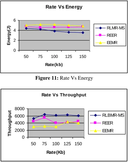
[image:6.612.322.547.224.670.2]Rate Vs Energy
0 2 4 6
50 75 100 125 150
Rate(kb)
E
n
e
rg
y
(J
)
[image:7.612.64.287.74.352.2]RLMR-MS REER EEMR
Figure 11: Rate Vs Energy
Rate Vs Throughput
0 2000 4000 6000 8000
50 75 100 125 150
Rate(Kb)
T
h
ro
u
g
h
p
u
t
RLBMR-MS
REER
EEMR
Figure 12: Rate Vs Throughput
Figure 8 gives the average end-to-end delay for all the protocols when the number of nodes is increased from 100 to 250. From the figure, it can be seen that the average end-to-end delay of the proposed RLBMR-MS protocol is less when compared with REER and EEMR protocols.
Figure 10 and 9 present the packet drop and packet delivery ratio of all the protocols, respectively. Since reliability is achieved using failure recovery of sinks, RLBMR-MS has less packet drops and achieves better packet delivery ratio when compared to other protocols.
Figure 11 shows the results of energy consumption for all the protocols. From the results, we can see that RLBMR-MS protocol has less energy consumption than all other protocols, since it has the energy efficient tree.
6. CONCLUSION
In this paper, we have proposed to develop a Fault detection and recovery mechanism for multiple sinks. The nodes are grouped into clusters based on the data generation rate and multiple sinks are deployed in the clusters in which the data generation rate is more. An energy efficient multi path tree is constructed towards the sink and the aggregated data from the sensors are transmitted to their nearest sinks through this multi path tree. The rate adjustment value and the inter arrival delay of each path is calculated and sent back as a feedback to the source to by the respective sinks. Then the path with the minimum feedback value is chosen as the best path for transmission. When a failure occurs in a sink, then it can be detected based on delay and remaining energy. Once the fault sink is detected, then the data is transferred to another sink or the sinks are deployed again. From our simulation results, we show that an efficient load balanced multi
path routing for multiple sinks is obtained and the fault detection and recovery can be made effectively.
7. ACKNOWLEDGMENTS
The authors wish to acknowledge J.S.S Research Foundation, S.J.C.E Technical institutions campus, Mysore, Karnataka, India for all the facilities provided for this research work.
8. REFERENCES
[1] Michael Ignatius Brownfield., 2006. Energy efficient Wireless Sensor Network MAC Protocol. Technical Report. Virginia Polytechnic Institute and State University.
[2] F. L. Lewis., 2004. Wireless sensor networks. To appear in Smart Environments: Technologies, Protocols, and Applications.
[3] Tao Cu.i, Lijun Chen., Tracey Ho., Steven H. Low., and Lachlan L. H. Andrew,. 2007. Opportunistic Source Coding for Data Gathering in Wireless Sensor Networks. In Proceedings of the 2007 conference on Diversity in computing.
[4] Kai-Wei Fan., Sha Liu., and Prasun Sinha., 2007. Structure free Data Aggregation in Sensor Networks. Journal of IEEE Transactions on Mobile Computing. 929-942.
[5] Konstantinos Kalpakis., Koustuv Dasgupta., and Parag Namjoshi., 2002. Maximum lifetime data gathering and aggregation in wireless sensor networks. In Proceedings of the 2002 IEEE International Conference on Networking (ICN'02), pp. 685—696.
[6] Mihaela Enachescu., Ashish Goe.l, Ramesh Govindan., Rajeev Motwani., 2006. Scale Free Aggregation in Sensor Networks. Journal of theoretical computer science. pp-15-29.
[7] Dorottya Vass., and Attila Vid´acs., 2007. Distributed Data Aggregation with Geographical Routing in Wireless Sensor Networks. IEEE International Conference on Pervasive Services.
[8] Deepak Ganesan., Ramesh Govindan., Scott Shenker., and Deborah Estrin., 2001. Highly-Resilient, Energy-Efficient Multipath Routing in Wireless Sensor Networks. ACM SIGMOBILE Mobile Computing and Communications.
[9] Shio Kumar Singh., M P Singh., and D K Singh., 2010. Routing Protocols in Wireless Sensor Networks –A Survey. International Journal of Computer Science & Engineering Survey (IJCSES).
[10]K. Saleem., N. Fisal., S. Hafizah., S. Kamilah., and R. A. Rashid., 2009. A Self-Optimized Multipath Routing Protocol for Wireless Sensor Networks. International Journal of Recent Trends in Engineering.
[11]U.B. Mahadevaswamy., and M. N Shanmukhaswamy., 2010. An Energy Efficient Reliable Multipath Routing Protocol for Data Gathering In Wireless Sensor Networks. International Journal of Computer Science and Information Security.
[12]U.B. Mahadevaswamy., and M. N Shanmukhaswamy., 2012. Delay Aware & Load Balanced Multi-path Routing in Wireless Sensor Networks. Springer Link
[14]Haiyang Liu., Zhi-Li Zhang., Jaideep Srivastava., and Victor Firoiu., 2010. PWave: A Multi-source Multi-sink Anycast Routing Framework for Wireless Sensor Networks. Springer link.
[15]Mujdat Soyturk., and Turgay Altila., 2007. A Routing Algorithm for Mobile Multiple Sinks in Large-Scale Wireless Sensor Networks. IEEE International Symposium on Wireless Pervasive Computing.
[16]Waleed Alsalih., Selim Akl., and Hossam Hassanein., 2007. Placement of multiple mobile base stations in wireless sensor networks. IEEE International Symposium on Signal Processing and Information Technology.
[17]Zolt´an Vincze., Rolland Vida., and Attila Vid´acs., 2007. Deploying Multiple Sinks in Multi-hop Wireless Sensor Networks. IEEE International Conference on Pervasive Services.
[18]Mohamed Younis., Meenakshi Bangad., and Kemal Akkaya., 2003. Base-Station Repositioning For Optimized Performance of Sensor Networks. IEEE Vehicular Technology Conference.
[19]Bashir Yahya., and Jalel Ben-Othman., 2009. REER: Robust and Energy Efficient Multipath Routing Protocol for Wireless Sensor Networks. IEEE GLOBECOM.
[20]Shujiang LI., Xin MA., Xiangdong WANG., and Minghao TAN., 2011. Energy-efficient multipath routing in wireless sensor network considering wireless interference. Journal of Control Theory Applications. pp-127–132, DOI 10.1007/s11768-011-0263-4.
[21]U.B. Mahadevaswamy M.N. Shanmukhaswamy, ‖Load Balanced Multi-path Routing Using Multiple Sinks in Wireless Sensor Networks―, International Journal of Computer Information Systems, Silicon valley publishers (accepted for publication in July 2012 issue
[22]Network Simulator, http:///www.isi.edu/ns/nsnam
9. AUTHOR PROFILE
Mr. U.B Mahadevaswamy completed his B.E. degree in Electronics and Communication from Mysore University in the year 1988, M.Tech in Industrial Electronics from Manglore University in the year 1995 and He is presently working as Associate Professor in the Department of Electronics and communication, Sri Jayachamarajendra college of Engineering, Mysore, Karnataka, India. He is doing his Ph. D in the area of Wireless sensor networks under the guidance of Dr. M.N Shanmukhaswamy. His field of interest includes Wireless sensor networks, Analog and mixed mode VLSI circuits, Control systems, Digital signal processing.