© 2018, IRJET | Impact Factor value: 6.171 | ISO 9001:2008 Certified Journal | Page 2993
STUDY OF PLASTIC DEFORMATION OF SOFT MATERIALS UNDER
IMPACT LOAD
Gurunatha
1, Neelakanta V londe
21,2
Department of mechanical engineering, MITE Moodbidri, Karnataka- 574225 india
---***---Abstract
- Metals have very attractive physical and mechanical properties. Elasticity and plasticity are two important properties with respect to mechanical engineering. Metals are used in applications such wire drawing, punching, extrusion etc. where we need the metals with high plasticity properties. Under impact load the study of plasticity is one important field. Under impact load the soft metals may deform or extrude. In this present research work, the behavior of soft metals such as lead, tin and nylon under impact load are studied. And properties are compared the standard izod impact test and compression test are also done to have more information about the above the materials. A novel drop weight set up was designed and exhibited for experimentation. The results show that lead exhibit better flow properties under impact loading. This gives new avenues to use lead as a safe guard material under conditions of impact loading.Keywords
—Elasticity, plasticity dropweight test, lead impact load.1.
INTRODUCTION
Thin-walled circular or square metal tubes are absorbs impact energy or collapsible energy by action of axial forces. It has been studied and widely applied in engineering field. This research have taken to the study if thin walled structures in this papers. As more and more new technologies are placed, some novel development of the structural members has been increasingly introduced. [1]Shujuan Hou et al. the presents the optimal design for tapered tubes of three different configurations such are hollow single, foam-filled single and collinear double tubes. As a major class of energy-absorbing components, the thin- walled tubes made of aluminum and its alloys are gaining growing popularity in a range of industrial designs mainly due to its low cost and high weight-stiffness efficiency. The differentiation is done among the different tapered profiles with the different optimization algorithms, and the crashworthiness merits of foam- filled tapered tubes are acknowledged. It can concluded that the optimal designs of the multi-cell tapered tubes are different under different angles under the loads [2]. It is also identified that the weighting factors for different load angles are critical in the multi-objective optimization design of the multi-cell tapered tubes with load angle uncertainty. Extensive efforts have been made for experimenting in some areas while other researchers are tried to improve for thin walled tubes with different materials to improve their performance including metallic and polymer foams. The tapered circular tubes with graded thickness (TCTGT) were fabricated by a tube
tapering machine and the forming effects on crush response to absorb the impact energy under axial loading were investigated [3]. The ridged tubes with sinusoidal patterns were studied to improve the energy absorption properties of traditional circular tubes and reduce the initial peak load. The effects of the radius-thickness ratio, wavelength, and amplitude of corrugated tubes under an axial impact were investigated [4].
The energy absorption characteristics of a type of conical tubes with graded thickness (CTGT) under oblique impact loads were investigated [5] as the increase in the degree of forming effects was not always found to be beneficial and moderate extent of forming was suggested in applications against oblique loads. The conclusion of this study will facilitate the crashworthiness design of CTGT structures with better performance when subjected to oblique loads.
Up to now, there is no proper study on the drop weight impact force of tapered rod of soft materials like tin, lead , nylon. These structures will extend the design domain of the structures and can definitely improve their crashworthiness performance. Experiments were carried out to investigate the deformation and energy absorption characteristics of soft materials subjected to impact loading and the results are reported in this paper.
2.
EXPERIMENTATION
Metals have very attractive physical and mechanical properties. Elasticity and plasticity are two important properties with respect to mechanical engineering. Metals are used in applications such wire drawing, punching, extrusion etc. where we need the metals with high plasticity properties. On the other hand there are various applications where metals should be strong and hard without minute deformation such as in building, heavy structures and machineries. But there are also some areas of application where elasticity is permitted to a small extent.
2.1 MATERIALS USED
2.1.1 High Strength Low Alloy Steel
© 2018, IRJET | Impact Factor value: 6.171 | ISO 9001:2008 Certified Journal | Page 2994 Table 1 High Strength Steel Properties:
Density 7.85 kg/ m3
Brinnel hardness 150
Ultimate tensile strength 758 MPa
Yield strength 366 MPa
Elongation of yield 21 %
Modulus elasticity 190 Gpa
Poisson's ratio 0.27
Percentage elongation 4 %
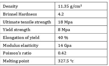
2.1.2 LEAD METAL
Lead is softer, more plasticity and high toughness. This is a shiny silver metal in a dry environment with a very light blue in the shadows. Just cut the head, there is a white and blue when exposed to the air. It is a complex mixture of compounds, according to the composition and terms of colors and sometimes large amounts of carbonate hydroxide carbonate.
Table 2 Lead(Pb) metal properties:
Density 11.35 g/cm3
Brinnel Hardness 4.2
Ultimate tensile strength 18 Mpa
Yield strength 8 Mpa
Elongation of yield 40 %
Modulus elasticity 14 Gpa
Poisson's ratio 0.42
Melting point 327.5 °c
2.1.3 TIN METAL
[image:2.595.82.244.99.214.2]Tin is a soft metal, silver, white, and blue light, known as the ancient bronzes, copper alloys. It is very light and easy to melt. Tin is widely used for food containers, small steel tanks. If soft pool rarely used as pure metals, on the contrary, with other metals, which have many beneficial properties of tin together. These include low toxicity and high resistance to corrosion.
Table 3 Tin (Sn) metal properties:
Density 7.3 g/cm3
Brinnel hardness 2.3 @ 100°c ,
3.9 @20°c
Ultimate tensile strength 220 MPa
Yield tension 4.50MPa @200°c
11 MPa @ 100°c
Elongation of yield 6.0% @ -200°c ,
45% @ 200°c
Modulus elasticity 41.6 GPa
Poisson's ratio 0.33
Melting point 231.96 °c
2.1.4 NYLON
[image:2.595.348.522.164.279.2]Nylon is a thermoplastic material, it is silky. All nylon materials have a high mechanical strength and high wear resistance and organic chemicals.
Table 4 Nylon material properties:
Properties Values
Density 1.11 g/cm3
Modulus of elasticity 2-4 GPa
Ultimate Tensile strength 80 MPa
Notched impact strength 0.23 kJ/m2
Thermal coefficient of expansion 80 x 10-6
Melting point 190-350°C
Elongation at break 60 %
2.2 METHODS
2.2.1 PROTOTYPE DESIGN
Prototype design has done using a software CATIA V5 tool. The model was designed as per dimension as shown in fig.1.
This prototype design considering taper die made up of high strength steel and billet made from tin, lead and nylon. Die has been designed smaller hole diameter is 10mm; angle 15° and the depth of taper hole is 60mm and 26mm is larger hole diameter of the die. Die is fixed and the billet is placed in taper hole, it may deform or extrude through this taper die.
A prototype is designed for purposed of new technique to absorb impact energy during head on collision in future scope. When a collision happens or suddenly applied unknown force, it would be withstanding the impact energy or may absorb energy from impact load. When a collision happens, load impacts on billet first, then the billet extrude through the taper die. It is best to design for making extrude the soft material through the taper die angle 15°. After billet comes out from die it could be channeled. In present work tin, lead and nylon materials were taken to extrude in die under the impact and static loading condition. If possible, we can reuse soft metals as per our requirement through casting.
[image:2.595.67.259.358.475.2] [image:2.595.63.565.619.786.2]© 2018, IRJET | Impact Factor value: 6.171 | ISO 9001:2008 Certified Journal | Page 2995
3.
RESULTS AND DISCUSSION
3.1 COMPRESSION TEST
The soft metals and nylon material were used for compression testing to make the extrusion or flow plasticity of materials through the taper die. It is comparable to the drop weight impact test specimen extrusion through taper die. Here calculating the billet length changes when apply the load gradually. After some interval, the material has deformed with application load. And also recorded the load and time
Area calculating of specimen Slant height of specimen L=
Lateral surface area AL = π*(R+r)*L Total area of specimen A = π*[(R+r)*L+R2+r2]
R = Larger radius (mm), r = smaller radius (mm), h = height of specimen (mm).
comp=
[image:3.595.310.559.345.495.2]Ductility in % = x 100
Table 5 Area calculation of materials
Table 6 Compressive strength and ductility results
The compression experiment has done by using a UTM with the maximum load capacity of 200 kN. The testing
was displacement changes with the machine top platen being moved vertically downward to compress the specimensand the loading speed was 1 mm/s.
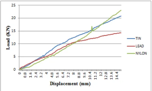
The taper specimens of tin, lead and nylon materials were used to obtain load v/s displacement curve by a compression test using at room temperature. The specimen is put into the taper die as shown in the fig.1. The die is placed in compression unit and applies the load. The compression load is recorded at every 0.1mm of displacement. After compressing the specimen to about 15mm displacement it is taken out of the pressing unit and notes the dimensions. Compared change in area of the specimen with the original area, we can get the ductility percentage of metals. The load and displacement diagram is drawn for three specimens. To simulate a plastic deformation of materials, the way portion approximated by smooth line mean the materials deformed plastically without rupturing (fig.2). The calculating done and compared the original specimen with deformed specimen after compressing the specimen as shown in the table 5 and table 6.
Fig.2. Load-Displacement plot under static load
Referring fig.2 the compression load increases gradually the material deformation is increasing. Three materials deformation is constant up to 10KN. After this load the lead is deformed more with the small loading condition means 44.18% of ductility about 4.05N/mm2. The tin is medium plasticity 40.16% of compression stress 5.47 N/mm2 and nylon consumes more load to short deformation compared to the lead about more than nylon 12.15% to about 6.67N/mm2.
Izod test
[image:3.595.37.292.441.605.2]© 2018, IRJET | Impact Factor value: 6.171 | ISO 9001:2008 Certified Journal | Page 2996 Fig.3.Impact strength and energy scatters diagram of
lead, tin and nylon.
Referred table 7 and fig.3., the results of test were lead exhibits low impact strength (0.085 J/mm2) compare to nylon (0.26 J/mm2) and tin (0.20 J/mm2). The lead absorbs less energy and gives more deformation. The tin is medium and the nylon materials absorb more impact energy gives less deformation.
Drop weight impact test
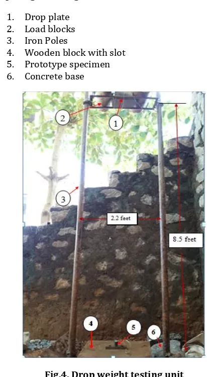
Drop weight impact testing is a weight is dropped from a known height and accelerated under the influence of the force of gravity. The weight has a similar hammer at the striking end thereof with that of Charpy and Izod processes. The hammer comes down and touches the sample material making some kind of failure or breaking, cracking, plastic deformation or a purely elastic deformation. With the method of weight loss, the weight is passed to the target material sample by dragging through a tube or slide along the guide rails. The acceleration of the impact mass can also be assisted by compressed air or springs to only increase the impact speeds above by gravity. A typical drop weight device is shown in Figure --- With this apparatus, the impact weight is drawn up to its release height by a chain where it is then released. Note how the apparatus has two guide rails on either side of the impact weight. The specimen is housed in the wooden box.
Drop weight impact tests are done for soft metals like lead and tin and also nylon material. This is most closely impact extrusion or material deformation in the field. The deformation material can be seen by the naked eye. It consist two iron poles placed in the ground. Drop plate made up of iron and rods is sliding through the iron poles. For smooth sliding the grease is pasted over the poles. The wooden block is placed in between the two poles and slot is made to block for placing the taper die. Weight blocks can be placed on the drop plate and clamp it and this drop plate can be locked by from hooks attached to pole. When released the locks weight can be dropped on the billet specimen and it will deform and flow through the taper channel in the die.
Specimen preparation and test setup:
The specimen used to drop weight testing the tapper die length 60mm and billet placed inside the taper die. The die made up of high strength steel and billets are lead and tin soft metals and nylon thermoplastic material. The material used is dependent on the desired result of the testing. the billets are made taper shape larger dia 30mm ; smaller dia 16mm and height is 70mm. This tapper die is placed in wooden block as made a slot in the wooden block as 50mm depth. The billet is placed in taper die and clamped. The mass is raised to the desired height and it is locked into place. When released the lock the whole mass dropped on the specimen. The effect of this the deformation material can occur.
Drop weight testing unit
1. Drop plate 2. Load blocks 3. Iron Poles
[image:4.595.37.284.70.213.2]4. Wooden block with slot 5. Prototype specimen 6. Concrete base
Fig.4. Drop weight testing unit
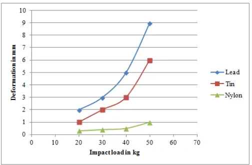
[image:4.595.320.526.274.649.2] [image:4.595.307.562.679.777.2]© 2018, IRJET | Impact Factor value: 6.171 | ISO 9001:2008 Certified Journal | Page 2997 The drop weight impact test conducted for three
masses 20 kg, 40kg and 50kg. For 20kg mass the lead, tin and nylon are deformed 2mm, 1mm and 0.3mm. When apply 50kg mass the lead and tin metals are deformed more as shown in fig. 5. Results by table 8, for 50 kg mass, the deformation of lead ,tin and nylon are 9mm,6mm and 1mm. According to these values the lead deforms plastically to a large extent under small impact loads as shown in fig. 5. In other words lead consumes more impact energy and exhibits higher flowability compared to other materials such as tin and nylon. It means lead can be extruded easily than the other two materials, even under impact load.
Fig.5. Load- Deformation of lead, Tin and Nylon Materials for Impact Load
The general equation for the impact stress
)
= ( 1+ )
2 2
W = weight, N
h = height of falling weight, mm δ = deformation of material, mm
to find strain ε =
[image:5.595.37.289.228.393.2]’= impact stress, N/mm2 E = young’s modulus, GPa
Table 9: Results of impact stress and strain
DISCUSSION
The study of soft material deformation under impact load test and compression test has been compared with respect to ductility of the materials. The tin, lead and nylon materials were used in this work. As compared to three materials, the ductility percentage of lead is more than tin and nylon materials under impact and compression loads.
As seen in the drop weight results for 50 kg mass, the deformation of lead, tin and nylon are 9mm, 6mm and 1mm. According to these values the lead deforms plastically to a large extent under small impact loads. We can conclude that the plasticity and ductility and toughness of lead are more than the tin and nylon. In other words, lead consumes more impact energy and exhibits higher flowability. It means lead can be extruded easily than the other two materials, even under impact load. This is also justified by the results of the test were lead exhibits high impact strength (0.85 J/mm2) compared to nylon (0.26 J/mm2) and tin (0.20 J/mm2).
As seen from compression test results the lead is more plastic under static compression load and followed by ten. ; the ductility percentage of lead metal is more plastic(44.18%) compared to tin(40.16%) and nylon(12.15%). According to these values flowability of lead is more under small compressive load (4.05 N/mm2) and also tin is medium (5.47 N/mm2) and nylon is less plastic consume more load. In other words, lead consumes less compressive strength and exhibits higher flowability. It means lead can be extruded easily than the other two materials, even under static loading condition.
Rate of loading:
It is the ratio of load applied per unit time in the present work. Three impact loading rates are considered. They are 20kg/Sec, 40kg/Sec and 50 kg/ Sec. The rate of linear deformation of lead is 9mm/Sec, under high rate of loading i.e. 50kg/Sec. Whereas tin had deformed 6mm/Sec under 50kg/Sec loading rate. This means that lead gets deformed rapidly compared to the tin with the about 1.5 times higher than the tin. In other words, this also proves that the lead can absorb large impact load than tin. This gives way to use lead as a metal, which can be utilized as a front guard material to avoid damage to other parts in case of a head on collision.
CONCLUSION
© 2018, IRJET | Impact Factor value: 6.171 | ISO 9001:2008 Certified Journal | Page 2998 avoid damage to other parts in case of a head on collision.
We can conclude also that, the new designed prototype model withstands high impact energy or absorbs more impact energy in case of a head on collision. Through this work, it can be concluded that the plasticity, ductility and toughness of lead is more than tin and nylon under impact load.
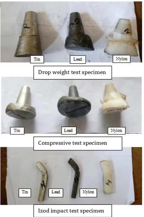
[image:6.595.37.279.191.556.2]Test wise specimen:
Fig.6. The deformed shapes of tested specimens
[1] Shujuan Hou a, XuHan a, GuangyongSun a,b, ShuyaoLong a, WeiLi b, XujingYang a, QingLi “Multi objective optimization for tapered circular tubes” Thin-Walled Structures 49 (2011) 855–863.
[2] Chang Qi,ShuYang, FangliangDong “Crushing analysis and multiobjective crashworthiness optimization of tapered square tubes under oblique impact loading. Thin-Walled Structures 59 (2012) 103–119.
[3] Xiong Zhang, HuiZhang , ZhuzhuWen “Axial crushing of tapered circular tubes with graded
thickness” International
JournalofMechanicalSciences92(2015)12–23.
[4] Zhifang Liu a, WenqianHao a, JiamiaoXie b, JingshuaiLu a, RuiHuang a, ZhihuaWang “Axial-impact buckling modes and energy absorption properties of thin-walled corrugated tubes with
sinusoidal patterns”
Thin-WalledStructures94(2015)410–423
[5] Xiong Zhang, HuiZhang “Relative merits of conical tubes with graded thickness subjected to oblique impact loads” International Journal of Mechanical Sciences 98(2015)111–125
[6] C. Galliot, J.Rousseau, G.Verchery “Drop weight tensile impact testing of adhesively bonded carbon/epoxy laminate joints” International Journal of Adhesion & Adhesives 35 (2012) 68–75
[7] F.Tarlochan a,n, F.Samer b, A.M.S.Hamouda c, S.Ramesh d, KaramKhalid “Design of thin wall structures for energy absorption applications: Enhancement of crashworthiness due to axial and
oblique impact forces”
Thin-WalledStructures71(2013)7–17
[8] Zhibin Li, JilinYu, LiuweiGuo “Deformation and energy absorption of aluminum foam-filled tubes subjected to oblique loading.” International Journal of Mechanical Sciences 54 (2012) 48–56.
[9] S. R. Reid ” plastic deformation mechanisms in axially compressed metal tubes used as impact energy absorbers deformation” Int. J. Mech. Sci. Vol. 35, No. 12, pp. 1035-1052, 1993
[10] Manmohan Dass Goel “Deformation, energy absorption and crushing behavior of single-,double-and multi-wall foam filled square single-,double-and circular tubes” Thin-WalledStructures90(2015)1–11. Compressive test specimen
Drop weight test specimen
Izod impact test specimen