© 2018, IRJET | Impact Factor value: 6.171 | ISO 9001:2008 Certified Journal | Page 753
A Real Time Design and Development of 2D Image Transmission using
Lifi Technology
Pragati P Waghale
1, Asst. Prof. Amita Thakare
21
Pragati P Waghale, Dept. of Electronics & Communication, Priyadarshini Bhagwati College of Engineering,
Harpur Nagar Umred Road Nagpur, Maharashtra, India.
2
Asst. Prof. Amita Thakare Dept. of Electronics & Communication, Priyadarshini Bhagwati College of Engineering,
Harpur Nagar Umred Road Nagpur, Maharashtra, India.
---***---Abstract -
The main objective of this project is to transmitthe image using LED (Light Emitting Diode). With the increasing popularity of solid state lighting devices, Visible Light Communication (VLC) is globally recognized as an advanced and promising technology to realize short-range, high speed and large capacity wireless data transmission. A LED light change in frequency quicker than the human eye can see, it likewise has higher recurrence than Radio wave which bring about considerably higher speed than Wi-Fi. In this report, a prototype of real-time image broadcast system using inexpensive commercially available light emitting diode (LED) lamps is proposed. The extent of the development is to utilize a LED Bulbs as a medium of information and communication in such a way that can be implemented in home, office, organization and industries. Experimental results show that real time image with the maximum distance of 2ft can be achieved through proper layout of LED sources and improvement of concentration effects. The design and construction of the LI-FI (Light Fidelity) light source enable efficiency, long stable life, as well as full spectrum intensity that is digitally controlled and easy to use.
Key Words
:Light Emitting Diode (LED), Light Fidelity (Li-Fi), Wireless Fidelity (Wi-Fi), Visible Light Communication (VLC), Photo Diode.1. INTRODUCTION
Li-Fi is a label for wireless-communication systems using light as a carrier instead of traditional radio Frequencies, as in Wi-Fi. Li-Fi has the advantage of being able to be used in sensitive areas such as in Aircraft without causing interference. However, the light waves used cannot penetrate walls. It is typically implemented using white LED light bulbs at the Downlink transmitter. These devices are normally used for illumination only by applying a constant current. However, by fast and subtle variations of the current, the optical output can be made to vary at extremely high speeds. This very property of optical current is used in Li-Fi setup. The operational procedure is very simple-, if the LED is on, you transmit a digital 1, if it’s off you transmit a 0. The LEDs can be switched on and off very quickly, which gives nice opportunities for transmitting data. Hence all that is required is some LEDs and a controller that code data into those LEDs. All one has to do is to vary the rate at which the LED’s flicker depending upon the data we want to encode. Further enhancements can be made in this method, like using
an array of LEDs for parallel data transmission, or using mixtures of red, green and blue LEDs to alter the light’s frequency with each frequency encoding a different data Channel. Such advancements promise a theoretical speed of 10 Gbps – meaning one can download a full high-definition film in just 30 seconds.
2. LITERATURE REVIEW
Li-Fi Technology: Data Transmission through Visible Light, International Journal Department of Computer Science by Anurag Sarkar, Prof. Shalabh Agarwal, Dr. Asoke Nath [July 2015]
Proposed system having Data transmission using Li-Fi technology, In this research the Li-Fi system successfully implemented using the visible light as a medium of communication, where the scattered light signals is used as a Data source through which data can be Transmit and Receive by communication devices.
The New Era of Transmission and Communication Technology: Li-Fi (Light Fidelity) LED & TED Based Approach, International Journal of Advanced Research in Computer Engineering & Technology (IJARCET) by Ravi Prakash, Prachi Agarwal [February 2014]
This very property of optical current is used in Li-Fi setup. The operational procedure is very simple-, if the LED is on, you transmit a digital 1, if it’s off you transmit a 0. The LEDs can be switched on and off very quickly, which gives nice opportunities for transmitting data. Hence all that is required is some LEDs and a controller that code data into those LEDs. All one has to do is to vary the rate at which the LED’s flicker [2] depending upon the data we want to encode.
A survey on Transmission of data through illumination-Li-Fi by M. Mutthamma Assistant Professor, Department of ECE, GCET, Hyderabad, A.P., India [12 December 2013]
© 2018, IRJET | Impact Factor value: 6.171 | ISO 9001:2008 Certified Journal | Page 754
3. BLOCK DIAGRAM
Li-Fi technology consist of transmission of image using LED light, The LED’s which is useful for image transmission and implement the basic concept of Li-Fi. It is divided into two modules Transmitter and Receiver.
3.1 Transmitter
Fig 1. Image Transmitter Module
The Block Diagram of the Li-Fi Transmitter Module is as shown in above figures 1. This Modules works in specific way which is explained below:
Transmitter Module: From Transmitter module, the Image Signal or Information form the Computer system is Serially send by USB-to-Serial Converter Which is interfaced to Raspberry PI for further processing. The Raspberry PI will convert it into PWM signal send it to the LED driver for its amplification. Raspberry PI generate PWM signal and demonstrate the PWM by varying the brightness of a LED Connected to PI. whereas LCD Connected with the Raspberry PI will display the status of the data transmission.
a. Computer System
Computer system which is used to provide the operation of image processing to be done at transmitter side by sending the image.
b. USB To Serial Converter
A USB adapter Converter is a type of protocol which is used for converting USB data signals to and from other communications standards. Commonly, USB adaptors are used to convert USB data to standard serial port data. The USB connector plugs into the computer's USB port. The data that are transmitted by the serial device are sent directly to the USB port.
c. Raspberry PI 0
Fig. 2 Raspberry PI 0
The Raspberry Pi 0 is the latest version of the Raspberry Pi, a tiny credit card size computer. Just add a keyboard, mouse, display, power supply, micro SD card with installed Linux Distribution and you'll have a fully-fledged computer that can run applications Raspberry PI comes preloaded with Python, the official programming language of the Raspberry Pi a Python Integrated Development Environment.
One powerful feature of the Raspberry Pi is the row of GPIO (general purpose input/output) pins along the edge of the board, next to the yellow video out socket. These pins are a physical interface between the Pi and the outside world. ... Seventeen of the 26 pins are GPIO pins; the others are power or ground pins.
Memory Of Raspberry PI - It has 512MB RAM (earlier
modelshave256MB), USB ports, 40 GPIO pins. It has 1GHz, single core CPU, Micro USB Power, Composite video and reset headers.
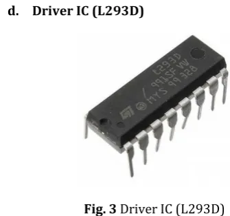
[image:2.595.318.558.82.253.2]d. Driver IC (L293D)
Fig. 3 Driver IC (L293D)
[image:2.595.37.291.164.354.2] [image:2.595.321.489.508.665.2]© 2018, IRJET | Impact Factor value: 6.171 | ISO 9001:2008 Certified Journal | Page 755 Circuit which allows the voltage to be flown in either
direction. As you know voltage need to change its direction for being able to rotate the motor in clockwise or anticlockwise direction, Hence H-bridge IC are ideal for driving a DC motor.
There are two Enable pins on l293d. Pin 1 and pin 9, for being able to drive the motor, the pin 1 and 9 need to be high. For driving the motor with left H-bridge you need to enable pin 1 to high. And for right H-Bridge you need to make the pin 9 to high. If anyone of the either pin1 or pin9 goes low then the motor in the corresponding section will suspend working. It’s like a switch.
e. LED Bulb
LED bulb is used as a medium which is used as a image transmission with high data rate. LED Bulb is cheap and fast optical device which can be used as light source as well as image transmission. The LED light appears constant to the human eye due to the fast flickering rate. The high data rate can be achieved by using high speed LED’s. The working principle of LED is depended on Visible Light Spectrum which have optical carrier range 400THz (780nm) to 800THz (375nm) for Visible Light Transmission. Pulse Rate used by LED’s is high for fast data transmission.
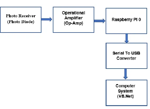
3.2. Receiver
Fig 4. Image Receiver Module
The Block Diagram of the Li-Fi Receiver Module is as shown in below figures 2.
Receiver Module: At Receiver side the encoded data signal through LED panel is received by Photodiode, the Photoreceiver will detect the digital data and decoded into the original format by the Raspberry PI which will sent to the Raspberry PI via USB to Serial converter.
a.
Photo Receiver (Photo Diode)A Photodiode is one type of light detector, used to convert the light into current and voltage based on the mode of
operation of the device. Photodiode is a PN-junction diode that consume light energy to produce electrical current. Some time it is also called as photo-detector, A light detector. This diode is very complex to light so when light falls on the diode it easily changes light into electrical current.
b.
Op-Amp (Operational Amplifier-LM 324)An operational amplifier (Op-Amp) is a DC-coupled high-gain electronic voltage amplifier with a differential input and, usually, a single-ended output. An Operational Amplifier (Op-Amp) is an integrated circuit that uses external voltage to amplify the input through a very high gain. Operational amplifiers. Amplifiers are devices which take a relatively weak signal as an input and produce a much stronger signal as an output.
The LM324 operational amplifier IC can be worked as a comparator. This a Low Power Quad Operational Amplifier and it has high stability, bandwidth which was designed to operate from a single power supply over a wide range of voltages.
4. WORKING
High brightness LEDs are the heart of Li-Fi technology. The logic is very straightforward. If the LED is ‘ON’, binary data ‘1’ is transmitted and if the LED is ‘OFF’ binary data ‘0’ is transmitted. These LEDs can be switched on and off at high speeds, giving huge opportunities for transmitting data through LED lights.
Step 1: Image is given as an input to the sender PC.
Step 2: Image processing is done in the sender PC, the output of which is processed by the Raspberry PI connected to PC via a serial port, This Image which is converted Image to Base64 format by using LI-FI Transmitter Software.
Step 3: Depending upon the output of Raspberry PI the led's connected to one of its port get toggled.
Step 4: At the receiver side photodetection takes place using photodiode placed at the receiver end. The photo detector will register a binary ‘1’ when the light is on and a binary ‘0’ when the light is off.
Step 5: Then the Raspberry PI at the receiver side conducts the binary conversion of the input data taken from phototransistor output.
[image:3.595.38.295.403.589.2]© 2018, IRJET | Impact Factor value: 6.171 | ISO 9001:2008 Certified Journal | Page 756
5. HARDWARE AND SOFTWARE USED
5.1 Hardware Used
1. USB To Serial Converter
2. Raspberry PI 3 3. Driver IC (L293D)
4. Op-Amp (Operational Amplifier LM324) 5. Photo Receiver (Photo Diode)
5.2 Software Used
1. Li-Fi Transmitter
2. Li-Fi Receiver
5.3 Language Used
1. VB.Net
2. Python Language
5.3.1 VB.Net Language
VB.Net is a simple, modern, object-oriented computer programming language developed by Microsoft to combine the power of .NET Framework. as part ofthe company's .NET product group, to make Web services applications easier to develop. VB.NET is a programming language designed to create applications that work with Microsoft’s new .NET Framework.
VB.Net was designed to take advantage of the .NET framework-based classes and run-time environment. It was re-engineered by Microsoft as part of its .NET product group.VB.NET supports abstraction, inheritance, and polymorphism.
VB.Net programming is very much based on BASIC and Visual Basic programming languages, so if you have basic understanding on these programming languages, then it will be a fun for you to learn VB.Net programming language. The syntax is easy and you will not find yourself writing hundreds of lines of code as there are many shortcuts that make coding so much easier in this language.
5.3.2 Python Language
Python is a general-purpose programming language; This Language has many strengths that make it a great language for embedded systems. Learning Python is really easy, a breeze if you've learned other object-oriented programming languages. It's recommended to be the first language people learns it contains all the concepts but is easier to read and less strongly typed as C++ or to a lesser extent Java.
6. EXPERIMENTAL RESULTS
6.1 Hardware Part
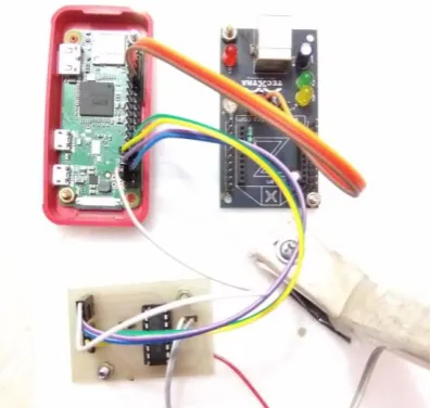
Fig 5. Transmitter Module with Raspberry PI
Fig 6. Receiver Module with Raspberry PI
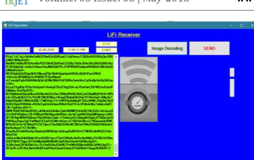
6.2 Software Part
[image:4.595.336.535.130.318.2] [image:4.595.338.527.329.531.2] [image:4.595.310.557.583.713.2]© 2018, IRJET | Impact Factor value: 6.171 | ISO 9001:2008 Certified Journal | Page 757 Fig 8. Receiver After Decoding
Explanation: - As Shown in Fig 5 the transmitter module which can send the image by using raspberry Pi to the receiver side, image is encoded through Li-Fi Transmitter software which is shown in fig 7. Photo detector which can receive the image, this Image can be seen by li-fi receiver software after decoding which is shown in fig 8.
7. RESULT AND DISCUSSION
Using Li-Fi Technology image transmission medium help to securely transmit the any information as it is overcome the disadvantage to leakage. Image can be send serially through an LED, Image can convert into base64 format and then transmitted. And the receiver ends this information which is converted into base64 to image format.
8. CONCLUSION
In future, data for laptops, smart phones & tablets can be transmitted through light in room by using Li-Fi. Researchers are developing micron sized LED which are able to flicker on & off around 1000 times quicker than larger LED. They offer faster data transfers and take up less space so we could save space or add more LED’s to further boost the channel of communication. If his technology can be put into practical use, every bulb can be used something like a Wi-Fi hotspot to transmit wireless data and we will proceed toward the cleaner, greener, safer and brighter future. The concept of Li-Fi is currently attracting a great deal of interest. This may solve issues such as the shortage of radio-frequency bandwidth and also allow internet where traditional radio-based wireless isn’t allowed such as aircraft or hospitals. One of the shortcomings however is that it only works in direct line of sight.
REFERENCES
[1] “A Real Time Design And Development Of 2D Image Transmission Using Lifi Technology” International Journal Of Engineering Science & Research Technology Department of Electronics and Communication by Asst. Prof. Amita thakre (Guide), PG Student Pragati P. Waghale. [March 2018]
[image:5.595.34.284.61.218.2][2] “Li-Fi Technology: Data Transmission through Visible, International Journal Department of Computer science By Anurag Sarkar, Prof. Shalabh Agarwal, Dr. Asoke Nath [July 2015].
[3] “Wireless Communication using Li-Fi Technology. SSRG International Journal of Electronics and Communication Engineering (SSRG-IJECE), by Karthika, R., &Balakrishnan, S. (2015).,
[4] “Image and video transmission using LED” by Aditya phatak, Mayur Suthar, Pratik Virulkar, Niraj Yadav, National conference on role of engineering in Nation Building (NCRENB-15), Vihar institude of technology shirgaon.
[5] The New Era of Transmission and Communication Technology: Li-Fi (Light Fidelity) LED & TED Based Approach International Journal of Advanced Research in Computer Engineering & Technology (IJARCET) by Ravi Prakash, Prachi Agarwal [February 2014].
[6] Sharma, R. R., & Sanganal, A. (2014). “Li-Fi Technology: Transmission of data through light. International Journal of Computer Technology and Applications.”
[7] Harald Burchardt, Nikola Serafimovski, Dobroslav Tsonev, Stefan Videv, and Harald Haas, “VLC: Beyond Point-to-Point Communication,” Communications Magazine, IEEE, 52(7), pp. 98-105, July 2014.
[8] ] “LI-FI Technology–A Visible Light Communication.” Bhut, J. H., Parmar, D. N., & Mehta, K. V. (2014).
[9] “A survey on Transmission of data through illumination-Li-Fi” by M. Mutthamma Assistant Professor, Department of ECE, GCET, Hyderabad, A.P., India International Journal of Research in Computer and Communication Technology, Vol 2, Issue 12, December-2013.
[10] Hacking Exposed Linux: Linux Security Secrets & Solutions (third ed.). McGraw-Hill Osborne Media.2008. p. 298. ISBN 978-0-07-226257-5. Sr. No. Parameters Wireless Technologies Light Fidelity Wireless Fidelity 1. Speed for data transfer Faster transfer speed (>1 Gbps) Data Transfer speed (150 Mbps) 2. Medium through which data transfers occurs Used Light as a carrier Used Radio spectrum 3. Network topology Point to point Point to point 4. Operating frequency Hundreds of Tera Hz 2.4 GHz 290.
[11] “New Chief Executive for the Engineering and Physical Sciences Research Council” 30 May 2007,